Table of Contents
Advertisement
Advertisement
Table of Contents

Subscribe to Our Youtube Channel
Related Manuals for Sundyne LMV-322


Summary of Contents for Sundyne LMV-322
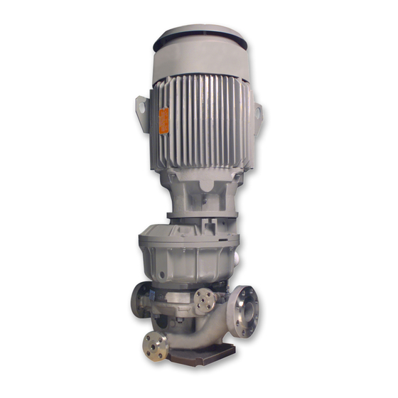
- Page 1 SUNDYNE LMV-322 PUMPS Instruction and Operation Manual JUNE 2009...
- Page 2 Warranty Sundyne Corporation warrants to Buyer for a period of twelve (12) months from the date of being placed in service (but not to exceed eighteen (18) months after the date of shipment) that the equipment at the time of shipment will be free from defects of design, material and workmanship.
- Page 3 Revisions April 2009 Add seal configurations / misc. updates Sundyne Corporation http://www.sundyne.com...
-
Page 4: Table Of Contents
Contents Contents..........iii Storing Your Pump Long-Term ..8 INTRODUCTION........1 Suction and Discharge Piping ....9 Sundyne Centrifugal Pumps ....1 Seal Environmental Control System10 Text Symbols ......... 1 Liquid Buffer System ......11 Equipment and Safety Precautions .. 2 Mounting Vertical Units Without Wearing Personal Protective Stands.............11... - Page 5 Parallel Operation....... 19 SPECIFICATIONS ......72 MAINTENANCE......... 20 Falk Steelflex Type Coupling Specifications ........72 Wet End Disassembly of LMV-322 ...20 Falk Double Gear Type Coupling Inspection, Cleaning and Repair ..25 Specifications ........72 Inspecting All Bearings...... 25 High-Speed Shaft ....... 25 Falk Double Gear Type-Vertical Gearbox Mechanical Seal....
-
Page 6: Introduction
Sundyne pumps are single stage that Sundyne centrifugal pumps. utilize an integral gearbox. Designed to increase Note: Parenthetical numbers included in the... -
Page 7: Equipment And Safety Precautions
Note: Safety procedures must be applied equipment occurs. prior to any installation, maintenance, Note: Sundyne recommends that a Lock- or repair of a Sundyne pump. Failure to out/Tag-out program be followed prior follow safety precautions may lead to to altering the equipment. Locks or tags... -
Page 8: Using Chemicals
Pre-Commission Checklist Familiarizing Yourself with the Pump Verifying Auxiliaries Before servicing and starting up the Sundyne Before start up, verify that the following pump, carefully review all information on the auxiliaries are met: product, including: •... -
Page 9: Installing A Seal Environmental Control System
If required, install drain piping overhead to connections are tight: ensure that the environment operates under • Pump flange bolts normal conditions. For more information, contact Sundyne Corporation. • Seal environment piping and port connections Checking Driver Rotation • Cooling water connections to heat If the driver is coupled, uncouple;... -
Page 10: Start-Up Checklist
Verify the following parameters against the accordance with the specification sheet. specifications on the specification sheet: Check with your Sundyne representative if the • Suction pressure operation conditions of your pump must run under different parameters than indicated by the •... -
Page 11: Installation And Start-Up Checklist
Your total satisfaction is our goal. Please call with any questions or comments. Be sure to have the unit serial number that is imprinted on the gearbox nameplate, and request “Sundyne Field Service”. Is all the information underlined above readily available? - Page 12 140-160°F (60-71°C) on units equipped with heat exchangers. Maximum recommended temperature is 180°F (82°C). Listen for any unusual noises or pressure fluctuations. Note: If you have any questions or concerns about these procedures or the information supplied, please call your representative or Sundyne Corporation.
-
Page 13: Installation
Factors which affect the quality of a Sundyne If your Sundyne pump will not be operated for a pump, when stored, are: period of time exceeding six months from the •... -
Page 14: Suction And Discharge Piping
Instruction and Operation Manual Suction and Discharge Piping Please adhere to the following best practices for 4. Sundyne recommends using a straight pipe installing and maintaining suction and discharge assembly of at least three times the length piping: of the pipe diameter on both suction and discharge of the unit. -
Page 15: Seal Environmental Control System10
Instruction and Operation Manual Seal Environmental Control System A seal environmental control system may be Ensure that the specified seal environmental required depending upon the pump seal control system is properly installed and that the arrangement and application. ports are open (or plugged) as indicated in Figure 1. -
Page 16: Liquid Buffer System
Drivers are interconnecting shaft is supplied, this shaft must to be installed and maintained in accordance be lubricated at each end with one tube (5cc) of with the manufacturer’s instructions. anti-fretting compound (Sundyne Part Number MP01AA10). -
Page 17: Flexible Coupling Lmv Units
Note: Lock out the driver starting switch before working on the coupling. When installing flexible couplings, use those supplied by Sundyne to ensure tolerance of parallel and angular misalignment, and axial end float. Use flexible disc couplings or gear type couplings if not using those supplied by Sundyne. -
Page 18: Lube System
LUBE SYSTEM Lube System • The internal lube oil system engineered for Oil filter Sundyne pumps consist of four major The lube pump intakes oil from the sump and components. They are: passes it internally to an integrally mounted •... -
Page 19: Remote Heat Exchanger
Gearbox Sump The gearbox sump holds approximately five U.S. Note: Sundyne recommends that the oil level quarts (4.7 liters) of oil, not including the oil must be within ¼” of top of the round... -
Page 20: Main Lube Pump
Instruction and Operation Manual Main Lube Pump The main lube pump is a positive displacement gear type pump directly driven by the input shaft. Figure 7. Lube Oil Schematic Oil Pressure During normal operation, the gearbox internal configuration and characteristics of the oil being lube pump will maintain oil pressure between 20 used.
Need help?
Do you have a question about the LMV-322 and is the answer not in the manual?
Questions and answers