Table of Contents
Advertisement
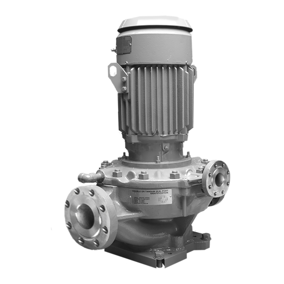
SUNDYNE
LMV-801 PUMPS
Instruction and Operation Manual
January 2009
th
14845 W. 64
Avenue • Arvada, Colorado 80007 USA • +1-303-425-0800 • FAX: +1-303-425-0896 •
www.sundyne.com
Sundyne Europe • Dijon (Longvic) • France • +33 (0) 3.80.38.33.00 • FAX: +33 (0)3.80.38.33.66
Sundyne Nikkiso • 27-10, Ebisu 2-Chome, Shibuya-Ku • Tokyo 150-0013, Japan • +81-3-3444-6475 • FAX: +81-3-3444-6806
ANSIMAG • ANYSPEED • CASTER • GSP • HMD/KONTRO • MASO/SINE • SUNDYNE COMPRESSORS • SUNDYNE • SUNFLO
Advertisement
Table of Contents

Subscribe to Our Youtube Channel
Related Manuals for Sundyne LMV-801


Summary of Contents for Sundyne LMV-801
- Page 1 Sundyne Europe • Dijon (Longvic) • France • +33 (0) 3.80.38.33.00 • FAX: +33 (0)3.80.38.33.66 Sundyne Nikkiso • 27-10, Ebisu 2-Chome, Shibuya-Ku • Tokyo 150-0013, Japan • +81-3-3444-6475 • FAX: +81-3-3444-6806 ANSIMAG • ANYSPEED • CASTER • GSP • HMD/KONTRO • MASO/SINE • SUNDYNE COMPRESSORS • SUNDYNE • SUNFLO...
- Page 2 Warranty Sundyne Corporation warrants to Buyer for a period of twelve (12) months from the date of being placed in service (but not to exceed eighteen (18) months after the date of shipment) that the equipment at the time of shipment will be free from defects of design, material and workmanship.
-
Page 3: Table Of Contents
Contents CONTENTS ......... II Storing Your Pump Long-Term ..6 INTRODUCTION........1 Suction and Discharge Piping ....7 Sundyne Centrifugal Pumps ....1 Seal Environmental Control System .7 Extended Motor Shaft Option..... 1 Liquid Buffer System ......8 Text Symbols ......... 1 START UP ........... 9 Equipment and Safety Precautions .. - Page 4 Integral Centrifugal Separator ..35 Common Parts List ......26 Extended Motor Shaft Adapter ..36 Single Seal Arrangement and Parts.27 Recommended Spare Parts List..37 Double Seal Arrangement and Parts ..............29 INDEX ..........40 Tandem Seal Arrangement and Parts ..............31 Sundyne Corporation http://www.sundyne.com...
-
Page 5: Introduction
Sundyne centrifugal pumps. Extended Motor Shaft Option Sundyne offers an extended motor shaft for use in extreme temperature conditions. The extended motor shaft and motor adapter separate the motor from the pump. This option is recommended when the process Adapter for extended temperature is below 0°... -
Page 6: Equipment And Safety Precautions
Note: Safety procedures must be applied All electrical sources must be powered-off prior to any installation, maintenance, before installation, service or repair of or repair of a Sundyne pump. Failure to equipment occurs. follow safety precautions may lead to injury! -
Page 7: Using Chemicals
Pre-Commission Checklist Familiarizing Yourself with the Pump Verifying Auxiliaries Before servicing and starting up the Sundyne Before start up, verify that the following pump, carefully review all information on the auxiliaries are met: product, including: •... -
Page 8: Installing A Seal Environmental Control System
Suction temperature accordance with the specification sheet. • Discharge pressure Check with your Sundyne representative if the • Total head operation conditions of your pump must run under different parameters than indicated by the •... -
Page 9: Installation And Start-Up Checklist
Your total satisfaction is our goal. Please call with any questions or comments. Be sure to have the unit serial number that is imprinted on the pump nameplate, and request “Sundyne Field Service”. Is all the information underlined above readily available? Are the following bolted/threaded connections tight? •... -
Page 10: Installation
Temperature required for long-term storage. • Surrounding chemicals If your Sundyne pump will not be operated for a period of time exceeding six months from the Long-term storage methods must prevent date of shipment, long-term storage conditions damaging conditions from making contact with must be met to ensure minimum corrosion the internal components of the equipment. -
Page 11: Suction And Discharge Piping
Sundyne be Suction and Discharge Piping Please adhere to the following best practices for 4. Sundyne recommends using a straight pipe installing and maintaining suction and discharge assembly of at least three times the length piping: of the pipe diameter. -
Page 12: Liquid Buffer System
Instruction and Operation Manual Figure 1. Seal Housing Port Identification Liquid Buffer System For double liquid seals and tandem liquid seals, Buffer flow should be 0.5 to 3 gpm (2 to 12 a liquid buffer system is used. Introduce the liters/min) with an inlet temperature of 60 buffer liquid into port 7, which will flow through F (16... -
Page 13: Start Up
Instruction and Operation Manual START UP Start-Up Procedures Perform the following tasks to start the Sundyne 4. Flushing screens should be installed in all pump. field assembled piping connections. 1. Run-in of pump: If the pump is to be run 5. -
Page 14: Operation & Control
Two conditions must exist to prevent damage to mechanical seals with the exception turbulence at the eye of the impeller. of double seals. If you have entrained gas, contact Sundyne for further instruction. • Proper suction piping, see suction piping section. -
Page 15: Parallel Operation
Instruction and Operation Manual even with the control valve wide open Figure 3. Parallel Operation (curve D). When the control valve is partially closed to create system curve E, the curve E and lower pump curve B are practically parallel. The lack of a significant angle of intersection means that the system is unstable;... -
Page 16: Maintenance
MAINTENANCE Disassembling the LMV-801 The following procedures apply to all STEP 2 configurations of the LMV-801 process pump Remove the inducer or impeller bolt. including the extended motor shaft and bearing box options. Refer to the specification sheet to determine your specific pump configuration and optional equipment included. - Page 17 Instruction and Operation Manual STEP 7 STEP 4 Remove the lower process seal. Remove the diffuser cover STEP 8 Remove the lower shaft sleeve and o-ring. STEP 5 Remove the lower seal rotating face. STEP 9 Remove the seal housing bolts. STEP 6 Remove the lower process seal bolts.
- Page 18 Instruction and Operation Manual STEP 11 Remove upper process seal or the throttle STEP 10 bushing. Remove the seal housing from the motor, bearing box or extended motor shaft adapter, as applicable. Seal housing with bearing box shown. Seal housing with extended motor shaft adapter shown.
-
Page 19: Inspection, Cleaning, & Shimming The Extended Motor Shaft
Dimension (1.73mm to 1.97mm incl) This section to be used with Reassembling the LMV-801 section, steps 3 and 4. The shaft shoulder dimension A as shown in figure 6 must be measured as described below. The motor must be positioned vertically with the shaft pointing upwards. -
Page 20: Shaft Sleeve
Instruction and Operation Manual Shaft Sleeve Replace or lap the seal rotating face if the wear track is rough or worn to a depth greater than 2 Ensure that there are no high spots on the end helium light bands. surfaces of the shaft sleeve or the impeller hub. -
Page 21: Reassembling The Lmv-801
Instruction and Operation Manual Reassembling the LMV-801 The following procedures apply to the LMV-801 STEP 3 (Extended shaft motors only) process pump single seal arrangement. For Check the shaft shoulder dimension to differences in the double and tandem seal determine number of shims required. - Page 22 Instruction and Operation Manual STEP 5 STEP 7 Install shaft sleeve on motor, bearing box or Install the lower shaft sleeve o-ring. extended shaft motor adapter, as applicable. STEP 8 Install the lower process seal and bolts. STEP 6 Install the thermal barrier gasket (if not previously installed) and seal housing on the bearing box or extended shaft motor adapter.
- Page 23 Instruction and Operation Manual STEP 9 STEP 12 Install the lower seal rotating face. Install diffuser and o-rings 936B and 936C. STEP 13 Install the seal housing and bearing box or extended motor shaft adapter (as applicable) onto the pump casing. STEP 10 Install the inducer cover and o-rings, 936D and 936E.
- Page 24 Instruction and Operation Manual Figure 7. Service Check Points...
-
Page 25: Troubleshooting
Instruction and Operation Manual TROUBLESHOOTING Pump Diagnostics • Several system factors may affect the Flow rate performance of the pump. These factors are: • Control characteristics • Temperature These factors as well as internal problems must • Specific gravity be considered when analyzing pump system performance. - Page 26 Instruction and Operation Manual Situation/Symptom Possible Cause Investigative/Corrective Action Insufficient total head Corrosion and/or erosion of diffuser throat (may If edge of throat is no longer sharp and smooth cont. also be accompanied by corrosion/ erosion of or has opened in size, head-rise may be diffuser and cover surface adjacent to impeller).
-
Page 27: Pump Mechanical Seal Diagnostics
Instruction and Operation Manual Pump Mechanical Seal Diagnostics The following table contains diagnostic Repair procedures for mechanical seals are information that is applicable to single seal, listed in this manual under Maintenance. double seal, and tandem seal equipped units. Table 2. Pump Mechanical Seal Diagnostics Situation/Symptom Possible Cause Investigative/Corrective Action... - Page 28 Instruction and Operation Manual Situation/Symptom Possible Cause Investigative/Corrective Action Chemical attack of seal faces, seal parts or Investigate fluid properties and determine o-rings. suitable materials for replacement. Damage to mechanical seal secondary seal Check for erosion and/or corrosion attack. (Teflon® wedge or U-cup or elastomer o-ring). Install seal flush or double seal arrangement.
-
Page 29: Specifications
Instruction and Operation Manual SPECIFICATIONS Table 3. Torque Values Gearbox Sundyne Standard Steel Screws & Bolts and NACE Compliant Steel Screws/Bolts (BG Material) Torque Values Item # Location Size English Metric 905H Oil Filter Manifold 3/8 - 16 x 1/2... -
Page 30: Common Parts List
Instruction and Operation Manual Common Parts List (Not Dependent on Seal Arrangement) Table 4. Common Parts List Item Part Name Item Part Name Pump Casing Stud Impeller 914A Hex Nut Impeller Bolt 916S Washer Impeller Key 918A Impeller Tab Washer 924B Bull Plug Inducer (Optional) -
Page 31: Single Seal Arrangement And Parts
Instruction and Operation Manual Single Seal Arrangement and Parts Figure 8. Single Seal Arrangement... - Page 32 Instruction and Operation Manual Table 5. Single Seal Arrangement Item No. Part Name Qty. Item No. Part Name Qty. Throttle Bushing (Upper) - Seal Face Washer Slinger Sleeve Assembly - Seal Spring Backup Disc Seal Rotating Face - Seal Retaining Ring Mechanical Seal - Seal Spring - Retainer and Drive...
-
Page 33: Double Seal Arrangement And Parts
Instruction and Operation Manual Double Seal Arrangement and Parts Figure 9. Double Seal Arrangement... - Page 34 Instruction and Operation Manual Table 6. Double Seal Arrangement Item No. Part Name Qty. Item No. Part Name Qty. Shaft Sleeve (Lower) - Retainer & Drive Sleeve Assembly Shaft Sleeve (Upper) - Seal Face Washer Seal Rotating Face - Seal Spring Backup Disc Seal Spacer - Seal Retaining Ring Mechanical Seal (Lower)
-
Page 35: Tandem Seal Arrangement And Parts
Instruction and Operation Manual Tandem Seal Arrangement and Parts Figure 10. Tandem Seal Arrangement... - Page 36 Instruction and Operation Manual Table 7. Tandem Seal Arrangement Item No. Part Name Qty. Item No. Part Name Qty. Shaft Sleeve (Lower) - Seal Retaining Ring Shaft Sleeve (Upper) - Seal Spring Seal Rotating Face - Seal Wedge Ring Seal Rotating Face Mechanical Seal (Alternate) Mechanical Seal (Lower) - Retainer &...
-
Page 37: Inducer & Parts
Instruction and Operation Manual Inducer & Parts Figure 11. Optional Equipment Table 8. Item Part Name QTY. Number Inducer Inducer Stud Alignment Pin Cover Gasket Chemical Barrier Gasket... -
Page 38: Diffuser Cone Extension
Instruction and Operation Manual Diffuser Cone Extension Figure 12. Diffuser Cone Extension Table 9. Item Part Name Qty. Number Pump Case Diffuser Diffuser Extension... -
Page 39: Integral Centrifugal Separator
Instruction and Operation Manual Integral Centrifugal Separator Figure 13. Integral Centrifugal Separator Table 10. Integral Centrifugal Separator Parts List Item No. Part Name Qty. Item No. Part Name Qty. Pump Casing 918L Separator Insert 936U O-ring Packing Separator Orifice 936V O-ring Packing Separator Fitting 936Z... -
Page 40: Extended Motor Shaft Adapter
Instruction and Operation Manual Extended Motor Shaft Adapter Figure 14. Extended Motor Shaft Adapter 914B 916S 916S 905A Table 11. Extended Motor Shaft Adapter Parts List Item No. Part Name Qty. Adapter, Extended Motor Shaft Shims As required Thermal Barrier Gasket 905A Hex Head Cap Screw 916S... -
Page 41: Recommended Spare Parts List
Instruction and Operation Manual Recommended Spare Parts List Table 12. Recommended Spare Parts List ITEM NO. PAGE NO. DESCRIPTION CLASS PUMP Impeller Key 3 (or 10) Impeller Bolt (or Inducer Stud) Thermal Barrier Gasket 115A Lip Seal RKORP801 O-ring Repair kit (Includes following) 936A - O-ring Packing 936D... - Page 42 Instruction and Operation Manual Notes: Seal repair kits for standard seals are Class 2: Minimum recommended spare available. O-rings for standard units are parts necessary to cover 1-2 available as a packaged o-ring Kit. The years of normal operation. o-ring repair kit does not include o-rings Class 3: Minimum recommended spare 936B and 936C.
- Page 43 Instruction and Operation Manual Figure 15. Pump Exploded View...
-
Page 44: Index
Pre-Commission Checklist, 3 Controlling the Pump During Startup, 9 Pressurizing Fluid Loop, 4 Diffuser Cone Extension, 33 Preventative Machine Guards, 3 Disassembling the LMV-801, 12 Pump Diagnostics, 21 Double Seal Arrangement and Parts, 28 Pump Exploded View Figure, 38 Driver Instructions, 3... - Page 45 Sundyne Europe • Dijon (Longvic) • France • +33 (0) 3.80.38.33.00 • FAX: +33 (0)3.80.38.33.66 Sundyne Nikkiso • 27-10, Ebisu 2-Chome, Shibuya-Ku • Tokyo 150-0013, Japan • +81-3-3444-6475 • FAX: +81-3-3444-6806 ANSIMAG • ANYSPEED • CASTER • GSP • HMD/KONTRO • MASO/SINE • SUNDYNE COMPRESSORS • SUNDYNE • SUNFLO...
Need help?
Do you have a question about the LMV-801 and is the answer not in the manual?
Questions and answers