
Related Manuals for Sundyne Sunflo P-3000 Series


Summary of Contents for Sundyne Sunflo P-3000 Series
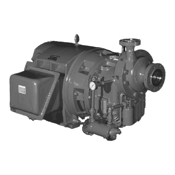
- Page 1 SUNFLO P-3000 with Journal Bearings Instruction & Operation Manual Visit our website at www.sundyne.com 02.10.02E, 6/2000 Effective: 6/2000 Supersedes: 6/97...
-
Page 2: Warranty
© 2000 Sunyne Corporation WARRANTY Sundyne Corporation warrants to Buyer for a period of twelve (12) months from the date of being placed in service (but not to exceed eighteen (18) months after the date of shipment) that the equipment at the time of shipment will be free from defects of design, material and workmanship. -
Page 3: Icons Used In This Manual
Safety alert. Failure to follow these procedures can endanger the safety of you or others. Electrical hazard. Failure to follow these procedures can endanger the safety of you or others. NOTES: Sunflo P-3000 = High Speed Centrifugal Pumps Visit our website at www.sundyne.com 02.10.02E, 6/2000... -
Page 4: Using This Manual
Sunflo P-3000 centrifugal pump. Parenthetical numbers included in the text correspond to item numbers located on the illustrated figures. Information that may be required and is not included herein may be obtained from your Sundyne Corporation distributor, or directly from the factory. -
Page 5: Pump Disassembly
10. Pump Disassembly Provides a detailed disassembly procedure for the gearbox and pump 11. Pump Assembly Provides a detailed re-assembly procedure for the gearbox and pump 12. Tool Drawings 13. Parts List General, Recommended Spares Visit our website at www.sundyne.com 02.10.02E, 6/2000... -
Page 6: Safety Precautions
Sunflo pump parts and accessories is considered misuse and damage or failure caused by misuse is not covered by Sundyne’s warranty. Additionally, modification of Sunflo products or removal of original components may impair the safety of these products and their effective operation. -
Page 7: Lock-Out/Tag-Out Guidelines
Auxiliaries 1. Check the utility connections. 2. Verify that the auxiliary piping conforms to Sundyne’s drawings. 3. Verify the connections of the switches, the instruments, and their settings. 4. Calibrate all measurement equipment (Flow meters, Current or Ampere meters, Pressure meters, etc.). -
Page 8: Heat Exchanger
Are the following bolted/threaded connections tight: a. Pump flange bolts? b. Seal environment piping and port connections? c. Cooling water connections to heat exchanger? (if applicable) d. Gearbox oil drain plug? e. Pump case drain plug? Visit our website at www.sundyne.com 02.10.02E, 6/2000... - Page 9 3. Make sure that the factory’s shipping covers for the housing flanges and the seal ports are securely in place. 4. Carefully follow the storage instructions provided by the manufacturer of the motor or turbine driver. Visit our website at www.sundyne.com 02.10.02E, 6/2000...
- Page 10 Because storage location and unknown factors at the site or storage are beyond our control, Sundyne does not accept any liability for damage to the equipment during storage, nor do we guarantee the quality of the equipment during and after the storage period. An Extended Warranty will be null and void if the proper equipment preparation is not maintained.
- Page 11 Additionally, a hot alignment check should be made once the pump has reached normal operating temperature. C. Coupling alignment should be verified only after the suction and discharge piping has been connected. Visit our website at www.sundyne.com 02.10.02E, 6/2000...
-
Page 12: Final Alignment
If a coupling is being used that was not supplied by Sundyne, it must be a flexible type, vibration- damping coupling. Refer to the coupling manufacturer’s recommendations for installation and alignment. To prevent personnel injury, lock-out the starting switch on the driver. - Page 13 M. Check valves should be placed on all installations where back flow through the pump is possible. If a check valve is installed in the discharge line, provisions should be made to vent the space between the pump and the check valve or the pump may not prime. Visit our website at www.sundyne.com 02.10.02E, 6/2000...
- Page 14 (1.05 kg/cm2) above the seal cavity pressure and at a controlled rate of 2.0 gpm (0.4 m /hr). Please refer to Paragraph G of this section for details concerning seal cavity pressure rise. Seal cavity pressure rise values are provided in Table 1. Visit our website at www.sundyne.com 02.10.02E, 6/2000...
- Page 15 3. Multiply this seal cavity pressure rise value by the specific gravity of the process fluid. 4. Specify the seal flush/buffer pressure to equal the sum of the suction pressure, the specific gravity corrected seal cavity pressure rise determined in Step G-3, and 15 psi (1.05 kg/cm Visit our website at www.sundyne.com 02.10.02E, 6/2000...
- Page 16 Process Specific Gravity: 0.95 Required Seal Flush/Buffer Pressure (RSFBP) = Suction Pressure + Seal Cavity Pressure Rise + 15 psig RSFBP = 19 psig + (20 psig)(0.95) + 15 psig RSFBP = 53 psig Visit our website at www.sundyne.com 02.10.02E, 6/2000...
- Page 17 P3-EEE P3-EGF P3-FCB P3-FEB P3-FCC P3-EFE (4.8) P3-EHF (4.8) P3-FDB (5.2) P3-FFB (5.5) P3-FDC (5.5) P3-EGE P3-FGB P3-FEC P3-EHE P3-FHB P3-FFC P3-EJE P3-FJB P3-FGC P3-FHC P3-FCD P3-FEE P3-FDD (5.5) P3-FFE (5.5) P3-FED P3-FGD Visit our website at www.sundyne.com 02.10.02E, 6/2000...
- Page 18 P3-MGF P3-NCB P3-NEB P3-NCC P3-MFE (70) P3-MHF (70) P3-NDB (77) P3-NFB (81) P3-NDC (81) P3-MGE P3-NGB P3-NEC P3-MHE P3-NHB P3-NFC P3-MJE P3-NJB P3-NGC P3-NHC P3-NCD P3-NEE P3-NDD (81) P3-NFE (81) P3-NED P3-NFD P3-NGD Visit our website at www.sundyne.com 02.10.02E, 6/2000...
-
Page 19: Pre-Start-Up
D. Remove the fill plug (Item P3-8) and fill the gearbox until the fluid level reaches the designated level on the sight glass. Approximately 8 quarts (7.5 liters) are required. E. Replace the fill plug and air vent plug. F. Remove the oil filter, fill with oil, and reinstall. Figure 3. Visit our website at www.sundyne.com 02.10.02E, 6/2000... - Page 20 Failure to pressurize the buffer system will allow the process fluid to contaminate the buffer fluid and may also allow contaminants in the process stream to damage the seal face. Visit our website at www.sundyne.com 02.10.02E, 6/2000...
- Page 21 The pump should be shutdown and the discharge and suction valves blocked in to isolate the pump and screen. After the strainer has been cleaned and reinstalled, the pump must be primed just as during the initial start up. Visit our website at www.sundyne.com 02.10.02E, 6/2000...
-
Page 22: Pump Operation
The user should be aware of the minimum flow recommendations for the Sunflo pump. While a pump can operate without harm with some noise due to recirculation, excessive noise and vibration are signs that the pump may be subject to damage if operation is continuous. Visit our website at www.sundyne.com 02.10.02E, 6/2000... - Page 23 N. Entrained gases in the fluid will reduce the head and capacity of a centrifugal pump. Entrained gases in the process stream may also damage the process seals. Entrained gases above 2 to 3 percent are considered to be the limits for a Sunflo pump. Visit our website at www.sundyne.com 02.10.02E, 6/2000...
- Page 24 Since the angle of intersection between the system curve and the performance curve is much larger, a larger change in pressure is required to provide the same change in flow as shown in Figure 4. Figure 5 Visit our website at www.sundyne.com 02.10.02E, 6/2000...
- Page 25 A and B are A2 and B2 respectively. If the control valve were closed even further, then Pump B would cease to flow entirely resulting in damage for dead-heading the unit. This situation can be avoided through the proper selection of the control system. Visit our website at www.sundyne.com 02.10.02E, 6/2000...
- Page 26 Figure 8 If individual throttle control valves on each pump as shown in Figure 8 are not available, Sundyne can modify the steepness of the Head-Flow curve by using a discharge orifice plate installed on the discharge of each pump, to assure proper parallel operation.
-
Page 27: Troubleshooting
Suction tank level or pressure too low. Entrained gases in pumped liquid. NPSH reduced by a more volatile process fluid. Failure of drive component Replace as necessary with Genuine Sundyne Parts. such as missing drive gear, sheared or missing impeller key, or failed high speed shaft bearing. - Page 28 Inspect remainder of pump to determine if other areas of pump are damaged from corrosion. Replace damaged parts. Establish corrosion mechanism. Determine if process conditions can be changed. Consult your authorized Sunflo sales representative for assistance on different pump materials of construction. Visit our website at www.sundyne.com 02.10.02E, 6/2000...
- Page 29 Pump discharge throat Disassemble pump and inspect pump casing for any obstructions. partially plugged. Replace hardware with Genuine Sundyne Parts if necessary. Driver speed too low. Check driver speed against value provided on the pump specification sheet. Driver Overloaded.
- Page 30 Gearbox lubricant is Check for excessive pump or seal leakage. Change gearbox oil normal color to milky pink contaminated with water or and replace all worn or damaged parts with Genuine Sundyne or yellow. process fluid. Parts. Inspect shaft sleeve o-rings. Replace if necessary.
-
Page 31: Pump Mechanical Seals
Replace seal and rotating face with Genuine Sundyne Parts if either part is shown to be worn or damaged Seal icing on low Use purge of dry nitrogen gas into seal drain area. Install double... - Page 32 Install a double seal system. face contacts. (Usually caused by icing from air in drain.) Chemical attack of seal Investigate process fluid properties and change seal and faces, seal parts, or o-rings o-ring materials if needed. Visit our website at www.sundyne.com 02.10.02E, 6/2000...
- Page 33 4. The ball bearings in the power frame of all frame-mounted units should be replaced every three years. These bearings are grease lubricated and are sealed off from the gearbox oil. Coupling 5. If a flexible coupling is used, refer to the manufacturer’s recommendations for service intervals. Visit our website at www.sundyne.com 02.10.02E, 6/2000...
- Page 34 Install an eye bolt to hold the casing with a hoist. Loosen and remove the remaining pump casing bolts. Step 2 Remove the pump casing by lifting and gently pulling it away from the gearbox Visit our website at www.sundyne.com 02.10.02E, 6/2000...
- Page 35 Remove the outboard journal bearing (Item P3- 23) from the gearbox housing by removing the cap screws. The bearing has two ¼”-20 UNC tapped holes for the temporary installation of jacking bolts to facilitate the removal of the bearing. Visit our website at www.sundyne.com 02.10.02E, 6/2000...
- Page 36 If you are unsure which lube pump design your Sunflo pump uses, refer to the pictures. Visit our website at www.sundyne.com 02.10.02E, 6/2000...
- Page 37 Step 9 The splash guard (Item P3-141) covering the drive gear must be removed prior to pulling the gear. Remove the two cap screws that hold the guard in place. Visit our website at www.sundyne.com 02.10.02E, 6/2000...
- Page 38 When using a torch, do not apply the flame to the gear teeth. Uniformly heat the gear keeping the flame close to the hub. Steps 12 through 14 of the disassembly procedure apply only to close coupled configured units. Visit our website at www.sundyne.com 02.10.02E, 6/2000...
- Page 39 Loosen the 3 set screws (Item P3-83) and remove the shaft sleeve (Item P3-84) and o-ring (Item P3- 82) from the motor shaft. Note: Steps 15 through 17 of the disassembly procedure apply only to frame mounted units Visit our website at www.sundyne.com 02.10.02E, 6/2000...
- Page 40 Step 17 (Frame Mounted Units Only) Using a soft hammer, gently tap on the driver end of the input shaft (Item P3-96) and remove the shaft and bearing assembly from the mounting frame. Visit our website at www.sundyne.com 02.10.02E, 6/2000...
- Page 41 2. Use 2 of the cap screws as jacking bolts on the journal bearing. Removal of the journal bearing will push the shaft out of the seal housing. Visit our website at www.sundyne.com 02.10.02E, 6/2000...
- Page 42 (Item P3-77), process seal rotating face (Item P3- 25), gearbox seal (Item P3-30), gearbox seal rotating face (Item P3-158), thrust runner (Item P3-151, and shaft sleeve (Item P3-22) inside the seal housing. Visit our website at www.sundyne.com 02.10.02E, 6/2000...
- Page 43 When the inboard journal bearing is removed, the oil deflector plate (Item P3-36) can also be removed. Visit our website at www.sundyne.com 02.10.02E, 6/2000...
- Page 44 (Item P3-77), process seal rotating face (Item P3-25), gearbox mechanical seal (Item P3-30), gearbox seal rotating face (Item P3-158), thrust runner (Item P3-151), and shaft sleeve (Item P3-22) inside the seal housing. Visit our website at www.sundyne.com 02.10.02E, 6/2000...
- Page 45 (Item P3-36) can also be removed. Step 26 (Double Seal Configuration Only) With the inboard journal bearing removed, the thrust runner and gearbox mechanical seal rotating face can now be removed. Visit our website at www.sundyne.com 02.10.02E, 6/2000...
- Page 46 When the inboard journal bearing is removed, the oil deflector plate (Item P3-36) can also be removed. Visit our website at www.sundyne.com 02.10.02E, 6/2000...
- Page 47 Using a hook-type device, remove the second seal snap ring (Item P3-108). Remove the outboard (secondary) process seal rotating face (Item P3-70). Using a hook-type device, remove the third seal snap ring (Item P3-108). Visit our website at www.sundyne.com 02.10.02E, 6/2000...
- Page 48 (Item P3- 64). The shaft sleeve slinger will engage on the seal retainer and push the seal out. Remove the gearbox mechanical seal (Item P3- 30). Remove all remaining o-rings. Visit our website at www.sundyne.com 02.10.02E, 6/2000...
-
Page 49: Pump Assembly
Press new ball bearings (Item P3-95) onto the input shaft. Ensure that the notched side of the inner races face each other. Visit our website at www.sundyne.com 02.10.02E, 6/2000... - Page 50 Install a new lip seal (Item P3-239) into the baffle plate (Item P3-190) by placing an arbor over the seal and lightly tapping the seal in with a hammer. Visit our website at www.sundyne.com 02.10.02E, 6/2000...
- Page 51 Install the baffle plate with 2 of the 4 socket head cap screws and lock washers. Steps 5 and 6 of the assembly procedure apply only to close coupled configured units. Visit our website at www.sundyne.com 02.10.02E, 6/2000...
- Page 52 11 and use a soft hammer to push the sleeve over the motor shaft. Push the sleeve until it bottoms out. Figure 11. Close Coupled Shaft Sleeve Installation. Tighten all 3 set screws (Item P3-83). Visit our website at www.sundyne.com 02.10.02E, 6/2000...
- Page 53 190°C) for at least 1 hour. Slide the gear onto input shaft and allow to cool. If the gear will not fit, then reheat the gear, shrink the motor shaft down with dry ice, and try again. Visit our website at www.sundyne.com 02.10.02E, 6/2000...
- Page 54 Install splash guard (Item P3-141) using the 2 remaining cap screws and lock washers. For a frame mount configuration, these cap screws will also be used to fasten the bearing housing retainer cap. Visit our website at www.sundyne.com 02.10.02E, 6/2000...
- Page 55 Step 11 Install the outboard journal bearing (Item P3-23) into the gearbox housing. Ensure that both o-rings (Item P3-181) have been installed around the OD of the bearing Visit our website at www.sundyne.com 02.10.02E, 6/2000...
- Page 56 90 degrees and try again. Step 13 Install the drain plug (Item P3-14) back into the gearbox housing. Install all lube pump piping including the heat exchanger and filter assembly. Visit our website at www.sundyne.com 02.10.02E, 6/2000...
- Page 57 Slightly stretch and lubricate the process seal o-ring (Item P3-28) and install into the o-ring groove in the seal bore. Install the process mechanical seal (Item P3-77) using the seal installation tool. (see page 83) Visit our website at www.sundyne.com 02.10.02E, 6/2000...
- Page 58 Slightly stretch and lubricate the gearbox seal o-ring (Item P3-28) and install into the o-ring groove in the seal bore. Install the gearbox mechanical seal (Item P3-30) using the seal installation tool. (See Figure 14) Visit our website at www.sundyne.com 02.10.02E, 6/2000...
- Page 59 Install the thrust runner (Item P3-151) by placing the part onto the gearbox mechanical seal rotating face. Ensure that the thrust runner is centered on the rotating face. Visit our website at www.sundyne.com 02.10.02E, 6/2000...
- Page 60 Install the inboard journal bearing with o-rings (Item P3-181) using the 4 cap screws and lock washers (Items P3-179 & P3-180). Use the cap screw at the 12 o’clock position to secure the oil fill deflector plate (Item P3-36). Visit our website at www.sundyne.com 02.10.02E, 6/2000...
- Page 61 Insert the shaft sleeve o-ring (Item P3-183) over the splined end of the high-speed shaft. Using a screw driver or similar tool, push the o-ring down the shaft until it is resting against gearbox mechanical seal rotating face Visit our website at www.sundyne.com 02.10.02E, 6/2000...
- Page 62 Slide the shaft sleeve (Item P3-22) onto the high- speed shaft. Push the sleeve into the assembly until it is resting against the gearbox mechanical seal rotating face and o-ring. Visit our website at www.sundyne.com 02.10.02E, 6/2000...
- Page 63 Install the impeller o-ring (Item P3-18) into the o-ring groove on the impeller hub, it will be necessary to lubricate the o-ring to keep it in the groove. Then slide the impeller over the splined end of the high-speed shaft. Visit our website at www.sundyne.com 02.10.02E, 6/2000...
- Page 64 Install the inducer o-ring (Item P3-58). Thread the inducer stud (Item P3-102) completely into the inducer. Install the inducer and tighten. Visit our website at www.sundyne.com 02.10.02E, 6/2000...
- Page 65 Step 26 (Single Seal Configuration Only) Install the seal housing o-rings (Item P3-148). Install the casing o-ring (Item P3-20). Visit our website at www.sundyne.com 02.10.02E, 6/2000...
- Page 66 Slightly stretch and lubricate the gearbox seal o-ring (Item P3-28) and install into the o-ring groove in the seal bore. Install the gearbox mechanical seal (Item P3-30) using the seal installation tool. (see page 83) Visit our website at www.sundyne.com 02.10.02E, 6/2000...
- Page 67 Install the gearbox seal rotating face (Item P3-158) by placing the part onto the gearbox mechanical seal. Ensure that the rotating face is centered on the seal face. Visit our website at www.sundyne.com 02.10.02E, 6/2000...
- Page 68 Install the thrust runner (Item P3-151) by placing the part onto the gearbox mechanical seal rotating face. Ensure that the thrust runner is centered on the rotating face. Visit our website at www.sundyne.com 02.10.02E, 6/2000...
- Page 69 Visit our website at www.sundyne.com 02.10.02E, 6/2000...
- Page 70 Install the inboard journal bearing with o-rings (Item P3-181) using the 4 cap screws and lock washers (Items P3-179 & P3-180). Use the cap screw at the 12 o’clock position to secure the oil fill deflector plate (Item P3-36). Visit our website at www.sundyne.com 02.10.02E, 6/2000...
- Page 71 Step 34 (Double Seal Configuration Only) Slide the shaft sleeve (Item P3-22) onto the high- speed shaft. Push the sleeve into the assembly until it is resting against the gearbox mechanical seal rotating face. Visit our website at www.sundyne.com 02.10.02E, 6/2000...
- Page 72 Install the inboard process mechanical seal (Item P3-77) using the seal installation tool shown on page 83. Ensure that the seal primary ring is facing away from the inboard side of the seal housing. Visit our website at www.sundyne.com 02.10.02E, 6/2000...
- Page 73 Failure to completely thread the stud may allow the inducer to come loose during operation and damage the pump. Install the inducer o-ring (Item P3-58). Visit our website at www.sundyne.com 02.10.02E, 6/2000...
- Page 74 Thread the inducer stud (Item P3-102) completely into the inducer. Install the inducer and tighten. Step 41 (Double Seal Configuration Only) Install the seal housing o-rings (Item P3-148). Install the casing o-ring (Item P3-20). Visit our website at www.sundyne.com 02.10.02E, 6/2000...
- Page 75 Visit our website at www.sundyne.com 02.10.02E, 6/2000...
- Page 76 The side with the narrow face must be in contact with the gearbox mechanical seal. Install the rotating face/thrust runner (Item P3-151) with the large face pointing outwards. Visit our website at www.sundyne.com 02.10.02E, 6/2000...
- Page 77 Sunflo sales representative to purchase the correct bearing. Failure to make this change will prevent the bearing from being adequately lubricated and will cause the pump to fail. Visit our website at www.sundyne.com 02.10.02E, 6/2000...
- Page 78 Step 46 (Tandem Seal Configuration Only) Slightly stretch and lubricate the inboard (primary) process seal o-ring (Item P3-28) and install into the o-ring groove in the seal housing bore Visit our website at www.sundyne.com 02.10.02E, 6/2000...
- Page 79 Slide the outboard shaft sleeve (Item P3-64) down the high-speed shaft until the sleeve slides over the o-ring and engages the gearbox seal rotating face/thrust runner. Visit our website at www.sundyne.com 02.10.02E, 6/2000...
- Page 80 Install the outboard (secondary) process mechanical seal (Item P3-77) using the seal installation tool (see page 83). Ensure that the seal primary ring is facing towards the suction side. Install the second seal snap ring (Item P3-108). Visit our website at www.sundyne.com 02.10.02E, 6/2000...
- Page 81 Slightly stretch the inboard shaft sleeve o-ring (Item P3-183) and slide the o-ring down the shaft. Using a screw driver or similar tool, push the o-ring down the shaft until it is flush with secondary rotating face. Visit our website at www.sundyne.com 02.10.02E, 6/2000...
- Page 82 Install the inboard (primary) process mechanical seal (Item P3-77) using the seal installation tool (see page 83). Ensure that the seal primary ring is facing towards the suction side. Install the fourth seal snap ring (Item P3-108). Visit our website at www.sundyne.com 02.10.02E, 6/2000...
- Page 83 P3-117) into the groove on the shaft sleeve face. Step 57 (Tandem Seal Configuration Only) Install the inboard (primary) process seal rotating face (Item P3-25) so that the rotating face engages the face of the outboard shaft sleeve. Visit our website at www.sundyne.com 02.10.02E, 6/2000...
- Page 84 Step 60 (Tandem Seal Configuration Only) Install the impeller o-ring (Item P3-18). It will be necessary to lubricate the o-ring to keep it in the groove. Then install the impeller over the splined end of the high-speed shaft. Visit our website at www.sundyne.com 02.10.02E, 6/2000...
- Page 85 Install the inducer o-ring (Item P3-58). Thread the inducer stud (Item P3-102) completely into the inducer. Install the inducer and tighten. Visit our website at www.sundyne.com 02.10.02E, 6/2000...
- Page 86 Step 62 (Tandem Seal Configuration Only) Install the seal housing o-rings (Item P3-148). Install the casing o-ring (Item P3-20) Visit our website at www.sundyne.com 02.10.02E, 6/2000...
- Page 87 Fasten the gear retainer into the end of the input shaft using the socket head screw and lock washer. Step 2 Install the lube pump relief spring into the retainer. Visit our website at www.sundyne.com 02.10.02E, 6/2000...
- Page 88 The lube pump manifold may be installed into the gearbox housing using the 2 socket head cap screws and lock washers. Ensure that the old gasket has been removed and a new gasket between the manifold and gearbox is used Visit our website at www.sundyne.com 02.10.02E, 6/2000...
- Page 89 Step 6 only applies when you have the lube oil system piping removed. Step 7 only applies when you have the lube oil system piping installed. Visit our website at www.sundyne.com 02.10.02E, 6/2000...
- Page 90 Repeat this procedure beginning at Step 1. If you continue to have problems with developing oil pressure, contact your Authorized Sunflo Sales Representative for technical assistance. Visit our website at www.sundyne.com 02.10.02E, 6/2000...
- Page 91 SEAL INSTALLATION TOOL DRAWING (PART NUMBER _________________________) (ALL DIMENSION IN INCHES) Figure 13 P-3000 CLOSE COUPLED MOTOR SHAFT SLEEVE ARBOR (PART NUMBER _________) (ALL DIMENSIONS IN INCHES) Figure 14 Visit our website at www.sundyne.com 02.10.02E, 6/2000...
-
Page 92: Parts List
Sundyne Corporation, Attention: Parts Order coordinator, 14845 W. 64 Avenue, Arvada, CO 80007, USA Phone: +1-303-425-0800 FAX: +1-303-425-0896 Sundyne Corporation, S.A.,Fluid Handling Division, DeKleetlaan 5, Box 1, B-1831Diegem, Belgium Phone: +322-719-78-70 Fax: +322-719-78-80 Nikkiso-Sundyne Company, Ltd., 17-10, Ebisu 2 Chome, Shibuya-Ku, Tokyo, Japan... - Page 93 P-3000 High Speed Shaft Assembly – Double Seals Figure 15 NOTE: P3-31 (Cover Plate) is integral to P3-19 (Seal Housing). Visit our website at www.sundyne.com 02.10.02E, 6/2000...
- Page 94 P-3000 High Speed Shaft Assembly – Single Seal Figure 16 Note: P3-31 (Cover Plate) is now integral to P3-19 seal housing Visit our website at www.sundyne.com 02.10.02E, 6/2000...
- Page 95 P-3000 High Speed Shaft Assembly – Tandem Seal Figure 17 NOTE: P3-31 (Cover Plate) is integral to P3-19 (Seal Housing). Visit our website at www.sundyne.com 02.10.02E, 6/2000...
- Page 96 Figure 18 Visit our website at www.sundyne.com 02.10.02E, 6/2000...
- Page 97 Figure 19 Visit our website at www.sundyne.com 02.10.02E, 6/2000...
- Page 98 P3-28 P3-147 P3-20 P3-148 P3-95 P3-42 P3-43 P3-116 P3-222 P3-5 P3-143 P3-190 P3-144 P3-3 P3-152 P3-100 P3-146 P3-145 P3-2 P3-161 P3-1 P3-121 P3-46 P3-17 P3-160 P3-64 P3-15 P3-14 P3-141 P3-62 P3-63 Figure 20 Visit our website at www.sundyne.com 02.10.02E, 6/2000...
- Page 99 Mounting Frame (Frame Mount Configuration) P3-121 Gearbox Housing O-Ring P3-132 Seal Flush Cap P3-139 Splash Guard Washer P3-140 Splash Guard Bolt P3-141 Splash Guard P3-153 Oil Filter Manifold P3-163 Oil Filter P3-175 Heat Exchanger Visit our website at www.sundyne.com 02.10.02E, 6/2000...
- Page 100 P3-146 Lube Pump Relief Spring P3-145 Lube Pump Retainer P3-144 Lube Pump P3-143 Lube Pump Manifold Assembly P3-142 Lube Pump Gear Retainer P3-113 Lube Pump Manifold Anti-rotation Pin P3-152 Lube Oil Manifold Gasket Visit our website at www.sundyne.com 02.10.02E, 6/2000...
- Page 101 Shaft Sleeve Inboard O-ring P3-148 Seal Housing/Gearbox Housing O-ring P3-151 Thrust Runner P3-158 Gearbox Mechanical Seal Mating Ring P3-179 Journal Bearing Screw P3-180 Journal Bearing Lock Washer P3-181 Journal Bearing O-ring P3-183 Shaft Sleeve Outboard O-ring Visit our website at www.sundyne.com 02.10.02E, 6/2000...
- Page 102 Inducer Stud Pe-108 Seal Snap Ring P3-117 Inboard Shaft Inboard O-ring P3-148 Seal Housing/Gearbox Housing O-ring P3-151 Thrust Runner/Gearbox Mating Ring P3-179 Journal Bearing Screw P3-180 Journal Bearing Lock Washer P3-181 Journal Bearing O-ring Visit our website at www.sundyne.com 02.10.02E, 6/2000...
- Page 104 SUNFLO Sundyne Corporation • Arvada, CO 80007 USA • +1-303-425-0800 • FAX: +1-303-425-0800 • www.sundyne.com Sundyne Europe • Longvic Cedex, France • +33-380-383300 • FAX: +33-380-383371...
Need help?
Do you have a question about the Sunflo P-3000 Series and is the answer not in the manual?
Questions and answers