
Subscribe to Our Youtube Channel
Related Manuals for Sundyne LMV-802


Summary of Contents for Sundyne LMV-802
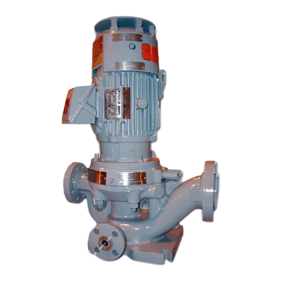
- Page 1 Installation, Operation & Maintenance Manual Sundyne Pumps Model: LMV-802 SA-07-11-37, Rev Orig. Jan 2009 SA-07-11-37 Rev Orig Jan 2009...
- Page 2 Warranty Sundyne Corporation warrants to Buyer for a period of twelve (12) months from the date of being placed in service (but not to exceed eighteen (18) months after the date of shipment) that the equipment at the time of shipment will be free from defects of design, material and workmanship.
-
Page 3: Table Of Contents
Driver Instructions ........ 4 OPERATION & CONTROL ....10 Verifying Auxiliaries ......4 Installing a Seal Environmental Operation of Sundyne Pumps ..10 Control System ........4 Suction Conditions ......10 Checking Driver Rotation ....4 Minimum Flow Conditions ....10 Piping Connections ...... - Page 4 SPECIFICATIONS ......29 Single Seal Arrangement ....36 Gearbox and Pump Torque Values.. Double Seal Arrangement ....37 .............. 29-30 Tandem Seal Arrangement ....38 Pump Spare Parts List ......31 INDEX ..........39 Inducer and Stud ........32 Pump Exploded View ......35 SA-07-11-37 Rev Orig Jan 2009...
-
Page 5: Introduction & Safety
Sundyne pumps are single stage that Sundyne centrifugal pumps. utilize an integral gearbox. Designed to to Note: Parenthetical numbers included in the... -
Page 6: Wearing Personal Protective Equipment
Note: Safety procedures must be applied tags must be provided to warn prior to any installation, maintenance, employees that equipment is or repair of a Sundyne pump. Failure to temporarily unavailable. follow safety precautions may lead to Once all work has been completed, the person... -
Page 7: Preventative Machine Guards
Note: Only remove the guards while Sundyne equipment. Any residual performing maintenance or repair. process gas or liquid that is flammable can result in an explosion or fire with Replace the guards immediately after working on the equipment and prior to start up. -
Page 8: Pre-Commission Checklist
Pre-Commission Checklist Familiarizing Yourself with the Pump Installing a Seal Environmental Control System Before servicing and starting up the Sundyne pump, carefully review all information on the Install a system to control the seal environment. product, including: Also, verify that port 1 is properly vented. -
Page 9: Start Up Checklist
Suction temperature • • Flow rate Discharge pressure • Power consumption Check with your Sundyne representative if the operation conditions of your pump must run • Specific gravity under different parameters than indicated by the • specifications in this manual. -
Page 10: Installation
Instruction and Operation Manual INSTALLATION Inspection Immediately inspect your Sundyne product upon Note: The input shaft on the pump may not receipt of the equipment. Check for any turn freely due to seal drag and speed damage, which may have occurred during increasing gear meshes. -
Page 11: Seal Environmental Control System
Instruction and Operation Manual Seal Environmental Control System A seal environmental control system may be Ensure that the specified seal environmental required depending upon the pump seal control system is properly installed and that the arrangement and application. ports are open (or plugged) as indicated in Figure 1 below. -
Page 12: Start Up
Note: Do not operate the pumps at their peak head capability. Parallel Operation Sundyne recommends that separate flow To prevent back-flow, place the check valves in controls be used on each pump to provide a the discharge piping of each pump. -
Page 13: Npsh - (Net Positive Suction Head And Cavitation)
It is also essential that once it is curve of Sundyne pumps. Flow control, on the selected that it is properly controlled. Use of flow other hand, can be quite precise and effective... -
Page 14: Operation & Control
Improper flow of liquid into the impeller is the of double seals. If you have entrained gas, most common operational abuse of centrifugal contact Sundyne for further instruction. pumps. Two conditions must exist to prevent turbulence at the eye of the impeller. -
Page 15: Parallel Operation
Instruction and Operation Manual that the pump flow is likely to drift Figure 4. Parallel Units Common Valve aimlessly and not respond to control valve position. Parallel Operation Maximizing control is critical when operating centrifugal pumps in parallel. One pump can overpower the other in regards to head at a lower total flow. -
Page 16: Maintenance
MAINTENANCE Disassembling the LMV-802 The following procedures apply to all STEP 2 configurations of the LMV-802 process pump. Refer to he specification sheet to determine your specific pump configuration and optional Remove the driver and seal housing from the equipment included. Disassembly should be pump casing (1). - Page 17 Instruction and Operation Manual STEP 4 STEP 3 Pry the impeller (2) from the drive shaft. Prevent Impeller from moving using a strap or chain wrench, loosen the inducer or impeller nut. Note: Left hand thread. Note: The impeller is dynamically balancedand should be replaced if it shows any sign of damage.
- Page 18 Instruction and Operation Manual STEP 6 STEP 9 Mark the position of the seal housing to the Remove seal housing gasket (87A). driver. These marks will ensure the seal housing will be in the correct position when reassembled. STEP 7 Remove the seal rotating face (51A).
- Page 19 Instruction and Operation Manual STEP 11 STEP 13 Turn the seal housing over and remove the Remove seal retainer spacer (19A). three hex head cap screws. STEP 12 STEP 14 Remove the throttle bushing (21B) and the Remove lower mechanical seal (60A) and the throttle bushing “O”...
- Page 20 Instruction and Operation Manual STEP 15 SINGLE SEAL Remove the throttle bushing (21B), seal Remove the seal spacer from the lower retaining spacer (19A), mechanical seal (60A), mechanical seal. and seal spacer (52). DOUBLE SEAL Remove the upper mechanical seal (60B), seal retaining spacer (19A), seal rotating face (51C), seal spacer (52), and lower mechanical seal (60A).
-
Page 21: Reassembling The Lmv-802
Instruction and Operation Manual Reassembling the LMV-802 The following procedures apply to the LMV-802 Replace the seal rotating face if the wear track process pump. Refer to the specification sheet is rough or is worn to a depth greater the to determine you specific pump configuration 0.0002 inch (0.005mm). - Page 22 Instruction and Operation Manual STEP 4 STEP 6 Install seal retainer spacer. Install throttle bushing onto the seal retainer spacer. STEP 7 Install the 3 throttle bushing hex head screws. Note: Torque to 100 In.-Lbs.. Installing the seal retainer spacer over mechanical seal and seal spacer.
- Page 23 Instruction and Operation Manual STEP 8 STEP 10 Install the thermal barrier gasket onto the Install the shaft sleeve “O” ring. driver. STEP 9 Install shaft sleeve onto the driver shaft. SA-07-11-37 Rev Orig Jan 2009...
- Page 24 Instruction and Operation Manual STEP 11 Lower the seal housing onto the driver. STEP 13 Install lower seal mating ring into the bottom of the seal housing. Note: Use hoist if possible to avoid personal injury. Use of a hoist also will help prevent damage to the thermal barrier gasket due to rough handling.
- Page 25 Instruction and Operation Manual STEP 14 STEP 16 continued Install inducer tab washer and inducer “O” ring onto the inducer.. Installing the inducer tab washer. Inserting the impeller key into the impeller. STEP 15 Install the impeller onto the driver shaft. Installing the inducer “O”...
- Page 26 Instruction and Operation Manual STEP 19 STEP 17 Prevent impeller from moving using a chain Install the inducer into the motor shaft. or strap wrench. Note: Left hand thread. STEP 20 Tighten the inducer. Note: Torque to 36-40 Ft.-Lbs. STEP 18 Punch a tab into the inducer slot.
- Page 27 Instruction and Operation Manual STEP 21 STEP 24 Bend tabs on tab washer into impeller holes. Lower the driver assembly onto the pump case. STEP 22 Flatten all the remaining tabs until flush with the impeller. STEP 23 Install case “O” ring onto seal housing. Note: Use hoist to prevent personal injury or possible damage to the pump.
- Page 28 Instruction and Operation Manual STEP 25 Install case nuts to fasten driver assembly to the pump casing. Note: Torque to 250 Ft.-Lbs. SA-07-11-37 Rev Orig Jan 2009...
-
Page 29: Troubleshooting
Instruction and Operation Manual TROUBLESHOOTING Troubleshooting the Sundyne LMV-802 PUMP Performance characteristics for this pump can be found on the Specification sheet and the performance curve. Information found in Table 1 can be useful in the analysis of pump performance problems. - Page 30 Instruction and Operation Manual TROUBLE POSSIBLE CAUSE INVESTIGATIVE/CORRECTIVE ACTION Insufficient flow or head rise. Process fluid specific gravity or viscosity Check actual viscosity and specific gravity at operating temperature. Viscosity higher (Continued) different from values shown on specification sheet. than five centipoise will cause reduced head and flow and increased power consumption.
-
Page 31: Pump Mechanical Seals
Instruction and Operation Manual Pump Mechanical Seals The following table contains troubleshooting procedures for units equipped with a single seal. The information also is applicable to single seal with throttle bushing, double and tandem seal units. Repair procedures for mechanical seals are listed in the maintenance section of this manual. Table 2. - Page 32 Instruction and Operation Manual TROUBLE POSSIBLE CAUSE INVESTIGATIVE/CORRECTIVE ACTION Sudden increase in seal leakage. Seal rotating face cracked or broken. Install double seal. (Continued) May be caused by damage at assembly Ensure that buffer fluid is always present or thermal shock caused by (1) seal during operation.
-
Page 33: Specifications
Instruction and Operation Manual SPECIFICATIONS Table 3. Gearbox and Pump Torque Values Gearbox Sundyne Standard Steel Screws & Bolts and NACE Compliant Steel Screws/Bolts (BG Material) Torque Values Item # Location Size English Metric 905H Oil Filter Manifold 3/8 - 16 x 1/2... -
Page 34: Pump Spare Parts List
Instruction and Operation Manual Pump Spare Parts List Figure 5. Pump Cross Section Table 4. Pump Spare Parts List ITEM NO. PART NAME ITEM NO. PART NAME Pump Casing Stud Impeller 914A Impeller Bolt 914B Impeller Key 916S Washer Impeller Tab Washer 924B Bull Plug Seal Housing... -
Page 35: Inducer And Stud
Instruction and Operation Manual Inducer and Stud Figure 6. Inducer and Inducer Stud Figure 7. Discharge Orifice SA-07-11-37 Rev Orig Jan 2009... - Page 36 Instruction and Operation Manual Figure 8. Centrifugal Separator Table 5. Centrifugal Separator Parts List ITEM PART NAME Separator Orifice Separator Fitting 905P Hex Head Cap Screw 916L Washer 918L Pin (Alignment) 936U “O” Ring Packing 936Z “O” Ring Packing *Recommended Spare Parts SA-07-11-37 Rev Orig Jan 2009...
- Page 37 Instruction and Operation Manual Table 6. Recommended Pump and Seal Spare Parts List ITEM PAGE NO. DESCRIPTION CLASS PUMP Impeller Key Impeller Tab Washer 3 (or 10) Impeller Bolt (or Inducer Stud) 936A O-Ring 936F O-Ring 936G O-Ring 936V O-Ring 936Z O-Ring Thermal Barrier Gasket...
-
Page 38: Pump Exploded View
Instruction and Operation Manual Pump Exploded View SA-07-11-37 REV ORIG JAN 2009... - Page 39 Instruction and Operation Manual Single Seal Arrangement Figure 9. Single Seal Arrangement Table 7. Single Seal Arrangement Item PART NAME ITEM PART NAME Seal retaining spacer -Seal Spring Back Up Disc Throttle Bushing -Seal Retaining Ring Slinger Sleeve -Seal Spring Seal Rotating Face -Seal Wedge Ring Seal Spacer...
-
Page 40: Single Seal Arrangement
Instruction and Operation Manual Double Seal Arrangement Figure 10. Double Seal Arrangement Table 8. Double Seal Arrangement ITEM PART NAME ITEM Part Name Seal Retaining Spacer Mechanical Seal (Upper) Shaft Sleeve (Lower) -Retainer & Drive Sleeve Assembly Shaft Sleeve (Upper) -Seal Face Washer Seal Rotating Face -Seal Spring Back Up Disc... -
Page 41: Double Seal Arrangement
Instruction and Operation Manual Tandem Seal Arrangement Figure 11. Tandem Seal Arrangement Table 9. Tandem Seal Arrangement ITEM PART NAME ITEM PART NAME Seal Retaining Spacer -Seal Spring Back Up Disc Shaft Sleeve (Lower) -Seal Retaining Ring Shaft Sleeve (Upper) -Seal Spring Seal Rotating Face -Seal Wedge Ring... -
Page 42: Tandem Seal Arrangement
Pump Mechanical Seals, 27 Controlling the Pump During Startup, 8 Pump Spare Parts List, 30 Copyright, 2 Recirculation, 9 Disassembling the LMV-802, 12 Recommended Seal Spare Component Parts, Double Seal Arrangement, 36 Driver Instructions, 4 Recommended Spare Parts, 36 Electrical Safety, 2... - Page 43 Sundyne Sundyne European Sundyne HMD Kontro Sealless Sundyne Marelli Pumps Headquarters Headquarters Pumps Ctra. Madrid-Toledo, KM.30.8 45200 Illescas 14845 West 64 Avenue Sundstrand International S.A. Brampton Road Toledo, Spain Arvada, Colorado 80007 13-15 Blvd.. Eiffel – B.P. 30 Hampden Park Industrial Estate...
Need help?
Do you have a question about the LMV-802 and is the answer not in the manual?
Questions and answers