Table of Contents
Advertisement
Quick Links
Advertisement
Table of Contents

Subscribe to Our Youtube Channel
Related Manuals for Sundyne LMV-313


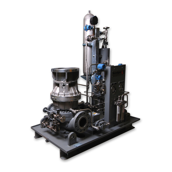
Summary of Contents for Sundyne LMV-313
- Page 1 SUNDYNE LMV-313 PUMPS Instruction and Operation Manual August 2007...
- Page 2 Warranty Sundyne Corporation warrants to Buyer for a period of twelve (12) months from the date of being placed in service (but not to exceed eighteen (18) months after the date of shipment) that the equipment at the time of shipment will be free from defects of design, material and workmanship.
-
Page 3: Table Of Contents
Storing Your Pump Long-Term ..3 OPERATION........12 PRODUCT DESCRIPTION ....4 Pre-Commissioning......12 Familiarizing Yourself with the Pump Sundyne Centrifugal Pumps ....4 ............... 12 Driver Instructions ......12 INSTALLATION ........5 Verifying Auxiliaries......12 Installing a Seal Environmental Suction and Discharge Piping.... - Page 4 Specifications ........40 ..............16 Single Operation......... 16 Falk Double Gear Type-Vertical Parallel Operation....... 16 Specifications ........41 Operation of Sundyne Pumps ..17 Thomas Type DBZ Coupling Suction Conditions ......17 Specifications ........41 Minimum Flow Conditions....17 Entrained Gases......... 17 Thomas SN Spacer Type Vertical &...
-
Page 5: Introduction & Safety
Failure to properly or repair of a Sundyne pump. Failure to select, install or use authorized Sundyne pump follow safety precautions may lead to parts and accessories is considered misuse and... -
Page 6: Wearing Personal Protective Equipment
EXPLOSION/FIRE HAZARD equipment occurs. Note: Never use an acetylene torch, open Note: Sundyne recommends that a Lock- flame, or heat to attempt to remove out/Tag-out program be followed prior parts that have seized together in to altering the equipment. -
Page 7: Transport And Storage
• Humidity If your Sundyne pump will not be operated for a • Temperature period of time exceeding six months from the date of shipment, long-term storage conditions •... -
Page 8: Product Description
Sundyne pumps are single stage that Sundyne centrifugal pumps. utilizes an integral gearbox. Designed to Note: Parenthetical numbers included in the... -
Page 9: Installation
Instruction and Operation Manual INSTALLATION Suction and Discharge Piping Please adhere to the following best practices for 4. Sundyne recommends using a straight pipe installing and maintaining suction and discharge assembly of at least three times the length piping: of the pipe diameter. -
Page 10: Seal Environmental Control System
Instruction and Operation Manual Seal Environmental Control System A seal environmental control system may be Note: Diffuser Cavity Vent must be vented to required depending upon the pump seal atmospheric drain. arrangement and application. Ensure that the specified seal environmental Always maintain the pump seal environment as control system is properly installed and that the detailed on the specification sheet that... -
Page 11: Mounting Vertical Units With Stands (Lmv)
Figure 2. Dimension X When installing flexible couplings, use those supplied by Sundyne to ensure tolerance of parallel and angular misalignment, and axial end float. Use flexible disc couplings or gear type couplings if not using those supplied by Sundyne. -
Page 12: Lube System
Lube System The internal lube oil system engineered for The lube pump intakes oil from the sump and Sundyne pumps consist of four major passes it internally to an externally mounted components. They are: manifold. The oil is then passed through the heat exchanger, the filter, and back into the •... -
Page 13: Oil Manifolds
Sundyne. (-29 C) it becomes too viscous for proper lube Note: Sundyne recommends that the oil level pump operation. A sump heater is required must be within ¼” of top of the round when these conditions may exist. Two types of... -
Page 14: Sundgard ® Oil Filter
Note: Oil filters other than Sundgard -OEM filters will void the Sundyne warranty. Main Lube Pump and Lube Oil Priming Kit To start the pump, allow the pre-lube pump to Note: Use the auxiliary lube oil priming pump run for approximately 30 seconds. -
Page 15: Oil Pressure
Instruction and Operation Manual Oil Pressure During normal operation the gearbox internal configuration and characteristics of the oil being lube pump will maintain oil pressure between 15 used. and 60 psig (1.0 and 4.2kg/cm ). This oil Note: Never operate the gearbox with oil pressure can vary depending on the bearing pressure less than 10 psig (0.7 kg/cm... -
Page 16: Commissioning, Start Up
Pre-Commissioning Familiarizing Yourself with the Pump Installing a Seal Environmental Control System Before servicing and starting up the Sundyne pump, carefully review all information on the Install a system to control the seal environment. product, including: Also, verify that port 1 is properly vented. -
Page 17: Pre-Start Up
Verify the following parameters against the accordance with the specification sheet. specifications on the specification sheet: Check with your Sundyne representative if the • Suction pressure operation conditions of your pump must run under different parameters than indicated by the •... -
Page 18: Installation And Start-Up Checklist
Is a check valve installed in the discharge line? Is port 1 open to atmosphere or piped to safety drain or flare or vent header? (Back pressure must not exceed 5 psig). Sundyne recommends the installation of a check valve in the flare piping to prevent backflow. -
Page 19: Start-Up Procedures
Note: If you have any questions or concerns about these procedures or the information supplied, please call your representative or Sundyne Corporation. Start-Up Procedures Perform the following tasks to start the Sundyne 6. Check to ensure the diffuser cavity vent is pump. -
Page 20: Controlling The Pump During Startup
Sundyne high-speed c) After the start of the main driver, oil products by providing a fluid film of lubricant pressure will be supplied by the main on the surfaces of bearings and gears. -
Page 21: Operation Of Sundyne Pumps
Instruction and Operation Manual 3. Open the discharge valve on the second unit Sundyne recommends that separate flow so that the design flow of both units is controls be used on each pump to provide a maintained. lower minimum flow range than is achieved by pressure control. -
Page 22: Parallel Operation
Instruction and Operation Manual (curve D). When the control valve is Figure 10. Parallel Units Common Valve partially closed to create system curve E, the curve E and lower pump curve B are practically parallel. The lack of a significant angle of intersection means that the system is unstable, pump flow is likely to fluctuate eratically and not respond to control valve position. -
Page 23: Maintenance
Instruction and Operation Manual MAINTENANCE Disassembly of LMV-313 STEP 2 Install the anti-rotation device to prevent impeller from spinning. STEP 1 Remove the nuts from the pump casing Note: Locking tools, part number TO01AK03 studs. Lift the gearbox and seal housing up for splined or TO01AK02 for coupled off of the pump casing. - Page 24 When a straight inducer is used, the diffuser will remain in the pump case. Build stand shown, part number T-MT-215, is available for purchase from Sundyne Corporation. STEP 7 Removing the bolts from the inducer housing.
- Page 25 Instruction and Operation Manual STEP 9 STEP 12 Remove o-ring 936A from the diffuser cover. Remove the impeller spacer and o-ring 936G. Note: These instructions reflect a tandem seal arrangement. If you have a single or STEP 13 double seal arrangement, refer to the seal arrangement drawings later in this Remove the lower seal rotating face and o- manual for differences.
- Page 26 Instruction and Operation Manual STEP 15 STEP 18 Remove the lower sleeve and o-ring 936J. Insert eyebolts into the seal housing for lifting. STEP 16 STEP 19 Remove the upper rotating face and o-ring Lift off seal housing. Be careful not to 936J.
- Page 27 Instruction and Operation Manual STEP 20 STEP 23 Remove upper sleeve and o-ring 936K. Remove the thermal barrier gasket. STEP 21 STEP 24 Remove the gearbox seal retaining bolts. Remove the gearbox seal rotating face. STEP 22 Use extraction tools to remove the rotating face. STEP 25 Remove the gearbox seal and o-ring 936P.
- Page 28 Instruction and Operation Manual STEP 26 STEP 28 Remove the alignment bolts. Remove the anti-rotation device. STEP 29 Remove fill and vent cap from gearbox. Note: Alignment bolts are close tolerance and must be removed first or damage may occur to the aluminum housing. Damage to the alignment bores can cause increased vibration and reduce gearbox life.
- Page 29 Instruction and Operation Manual STEP 31 STEP 33 Lift off the upper housing. Remove the input shaft. STEP 34 Remove the bearing plate. Turn over for high speed bearing removal. Note: If necessary, a screwdriver (use cloth to protect the aluminum) can be used in the slots to assist in breaking the seal between housings.
- Page 30 Instruction and Operation Manual STEP 35 STEP 38 Remove the upper journal bearing and thrust Remove the lower journal bearing. washer, if supplied, from the bearing plate. STEP 39 STEP 36 Remove the lube pump from the bearing Remove the idler shaft and high-speed shaft plate.
-
Page 31: Inspection And Cleaning And Repair
Instruction and Operation Manual Inspection and Cleaning and Repair Inspecting All Bearings new washer. If the tilting pads do not fit freely, or if they show signs of metal pick-up or overheating, install a new bearing assembly. Note: The radial “free play” of the high speed shaft can be as high as 0.011 inch (0.28mm) due to the clearance in the bearings. -
Page 32: Upper Shaft Sleeve
Instruction and Operation Manual Upper Shaft Sleeve Ensure that there are no high spots on the end surfaces of the shaft sleeve or the impeller hub. High spots will distort the seal rotating face due to the clamping force of the impeller bolt. Ensure that shaft sleeve end faces are parallel within 0.0003”... -
Page 33: Pump Assembly And Clearance Adjustments
Instruction and Operation Manual Pump Assembly and Clearance Adjustments General Clearance Adjustment place the parts within tolerances for the position specified in the Impeller Shim Adjustment figure. Information Note: Some diffuser openings are much wider If disassembly of the wet-end is only for minor than the impeller openings. - Page 34 Instruction and Operation Manual Insert the inducer housing (6) into the diffuser off any layers that are not needed. Remove the bore without the o-ring (936CA) and shims inducer housing (6) and install the shim (158F), (158F) installed. Install the crossover bar from o-ring (936CA), and inducer housing (6) in the the shaft loading tool and torque the nut for the diffuser.
- Page 35 Instruction and Operation Manual Figure 13. Shaft Loading Tool Installation Figure 14. Inducer Housing Adjustment...
- Page 36 Instruction and Operation Manual Figure 15. Inducer Housing Shim Adjustment...
-
Page 37: Procedure For Checking The High-Speed Shaft Endplay And Shoulder Height
Dry bearings are required to make the adjustments. Any presence of oil under the Step 7 thrust surfaces will produce inaccurate readings. Shims supplied by Sundyne Corporation usually Step 1 come in thicknesses of 0.005” to 0.010”. Select the shims that best obtain the shaft extension Install the bearings (151A &... - Page 38 Instruction and Operation Manual Figure 16. Output Shaft Shim Adjustment Note: Shims (158) are adjusted to obtain noted shaft end float and noted shaft extension. Shaft extension must be checked with thrust in noted direction. Measurements are made with dry (no oil) bearings.
-
Page 39: Assembly Clearance Data Sheet
Instruction and Operation Manual Assembly Clearance Data Sheet CUSTOMER SERIAL NUMBER DATE ASSEMBLER Shim above high speed shaft SP01AA04 Item 158 Shim below high speed shaft SP01AA04 Item 158 High speed shaft end play 0.015” ± 0.002” High speed shaft extension 1.203”... - Page 40 Instruction and Operation Manual Figure 17. Service Check Points...
-
Page 41: Specialty Tools
Instruction and Operation Manual Specialty Tools Overhauling the Sundyne LMV 313 pump in the also allows for more consistency in adjusting the field requires a couple of specialty tools that are impeller and inducer housing shims. See the not generally needed while overhauling other following figures for details. - Page 42 Instruction and Operation Manual Figure 19. Shaft Loading Tool Details Item Description Qty. 1 x 3 rectangle bar stock or 1 x 3 inch channel (steel) Same as item 1 Tension bolt (loads impeller and rotating assembly) Flat washer ¾” Nut ¾-10 UNC Bolt ¾-10 UNC, 8”...
-
Page 43: Impeller Locking Tool
Instruction and Operation Manual Impeller Locking Tool Tapered Inducer The impeller must be kept from rotating when The tapered inducer must be installed only after attempting to torque the inducer. The inducer the diffuser and inducer housing are in place. Do must have 85-90 ft-lbs of torque (116-123 N-m) not lock the impeller by inserting a rod thru the applied to it. -
Page 44: Falk Steelflex Type Coupling Specifications
Instruction and Operation Manual Falk Steelflex Type Coupling Specifications Table1. Falk Steelflex Type Coupling Specifications Falk Coupling End Gap Cover Bolt Size Torque Minimum Normal Maximum 40T10 0.062 in. 0.125 in. 0.188 in. 100 in-lb (1.57 mm) (3.17 mm) (4.77 mm) (1.15 kg-m) 50T10 0.062 in. -
Page 45: Falk Double Gear Type-Vertical Specifications
Instruction and Operation Manual Falk Double Gear Type-Vertical Specifications Table 3. Falk Double Gear Type-Vertical Specifications Operating Limits Falk Coupling (Total Indicator Limit) Bolt Size Torque Offset Angular (Maximum) (Maximum) 15GL 0.005 in. 0.005 in. 280 in-lb 15GV (0.127 mm) (0.127 mm) (3.22 kg-m) 20GL... -
Page 46: Thomas Sn Spacer Type Vertical & Horizontal Coupling Specifications
Instruction and Operation Manual Thomas SN Spacer Type Vertical & Horizontal Coupling Specifications Table 5. Thomas SN Spacer Type Vertical & Horizontal Coupling Specifications Thomas End Gap Operating Limits Bolt Torque Coupling Total Indicator Size Reading Minimum Normal Maximum Offset Angular (Maximum) (Maximum) -
Page 47: Gearbox Lube Oil Specifications
Instruction and Operation Manual Gearbox Lube Oil Specifications Table 6. Gearbox Lube Oil Specifications Recommended Gearbox Lube Oil Specifications API Gravity 28 – 37 Pour Point, °C (°F) -7 (20) max. Flash Point, °C (°F) 204 (400) min. Viscosity, cST at 40°C 28.8 to 35.2 (150/180 SSU @ 100°F) Viscosity, CST at 100°C 5.2 (44 min. -
Page 48: Gearbox And Pump Torque Values
Instruction and Operation Manual Gearbox and Pump Torque Values Table 7. Gearbox and Pump Torque Values Gearbox Sundyne Standard Steel Screws & Bolts and NACE Compliant Steel Screws/Bolts (BG Material) Torque Values Item # Location Size English Metric 905H Oil Filter Manifold... -
Page 49: Reassembling The Lmv-313
Instruction and Operation Manual Reassembling the LMV-313 STEP 1 STEP 3 Install all lube jets. Install lower journal bearing. Note: Torque to 28-31 in-lbs. Install all plugs and install the lube pump in the bearing plate. Step 4 Install tilting pad thrust bearing. - Page 50 Instruction and Operation Manual STEP 6 STEP 8 Install upper thrust washer onto the upper Install bearing plate onto the lower housing journal bearing. without gasket or o-ring. Note: Use a small amount of petroleum jelly to STEP 9 hold washer in place. STEP 7 Use alignment bolts to align the bearing plate.
- Page 51 Instruction and Operation Manual STEP 11 STEP 13 Inspect endplay of the high-speed shaft. Install idler shaft and high-speed shaft assembly. Note: Endplay must fall within these tolerances, (.015” +/- .002”) STEP 14 Note: For complete instructions for checking Install the bearing plate, gasket and o-ring. endplay and shaft shoulder height see the Procedure for Checking High- Speed Shaft End Play and Shoulder...
- Page 52 Instruction and Operation Manual STEP 16 STEP 19 Install upper gearbox housing. Install the vent cap. STEP 20 STEP 17 Install the anti-rotation tool. Install the two alignment bolts, turning the nuts but not the bolts. Then install the remaining housing bolts. STEP 21 STEP 18 Install the gearbox seal rotating face,...
- Page 53 Instruction and Operation Manual STEP 22 STEP 24 Install upper shaft sleeve and o-ring 936K. Install upper process seal and o-ring 936H onto seal housing. Install o-ring 936J. Note: Torque hex head screws to 95-102 in-lbs. STEP 25 Install the seal housing. Note: Before installing the seal housing insert the bolts for the seal housing into holes and temporarily install nuts on them to...
- Page 54 Instruction and Operation Manual STEP 26 Install upper process seal rotating face. Note: Torque process seal hex head screws to 95-102 in-lbs. STEP 27 STEP 29 Install the lower process seal shaft sleeve. Install lower mating ring, o-ring 936G, and Install two 936J o-rings, one on the top of the impeller spacer 158C.
- Page 55 Instruction and Operation Manual STEP 31 Note: Refer to the Specialty Tools section later in this manual for additional information on the shaft loading tool. Install the impeller and 936F o-ring. Apply anti-seize to the inducer stud. Note: The diffuser cover is not installed for this step.
- Page 56 Instruction and Operation Manual Torque shaft loading tool. Note: An Assembly Clearance Data Sheet is provided later in this manual to record your measurements. STEP 35 Remove the impeller and shaft loading tool and install the diffuser cover and o-ring 936E.
- Page 57 Instruction and Operation Manual STEP 38 STEP 41 Install the diffuser onto the seal housing. Install the inducer housing, shims, and o-rings 936C and 936CA. Note: Ensure that the inducer tool doesn't Note: Offset bolt pattern. rotate while torque is applied on the loading tool.
- Page 58 Instruction and Operation Manual STEP 44 STEP 47 Install the correct shims to maintain the Install T-hooks for lifting the gearbox. tolerance in the last step. Then install the inducer housing and o-rings 936CA and 936C. STEP 48 Note: Return to step 26 if using Teflon or Lift gearbox up and position over the pump graphoil o-rings.
-
Page 59: Troubleshooting
Instruction and Operation Manual TROUBLESHOOTING Gearbox & Pump Diagnostics • Several system factors may affect the Flow rate performance of the pump. These factors are: • Control characteristics • Temperature These factors as well as internal problems must • Specific gravity be considered when analyzing pump system performance. - Page 60 Instruction and Operation Manual Situation/Symptom Possible Cause Investigative/Corrective Action Diffuser discharge throat partially plugged or Clean these areas of all obstructions and restore Insufficient total head impeller damaged by passage of a solid particle. surfaces to a smooth polished finish free of all cont.
- Page 61 Instruction and Operation Manual Situation/Symptom Possible Cause Investigative/Corrective Action Change of gearbox oil Gearbox oil contaminated with water or process Inspect gearbox heat exchanger for leakage. from normal color to fluid. Check for excessive pump seal leakage. milky pink or yellow Inspect shaft sleeve o-rings.
-
Page 62: Pump Mechanical Seal Diagnostics
Instruction and Operation Manual Pump Mechanical Seal Diagnostics The following table contains diagnostic Repair procedures for mechanical seals are information that is applicable to single seal, listed in this manual under Maintenance double seal, and tandem seal equipped units. Table 9. Pump Mechanical Seal Diagnostics Situation/Symptom Possible Cause Investigative/Corrective Action... - Page 63 Instruction and Operation Manual Situation/Symptom Possible Cause Investigative/Corrective Action Chemical attack of seal faces, seal parts or Investigate fluid properties and determine o-rings. suitable materials for replacement. Excessive radial high speed shaft movement. Check high speed shaft journal bearings and replace if necessary.
-
Page 64: Drawings & Parts Listing
*Seal Repair Kits are Available and contain all parts marked with a single asterisk. Item 60C to be used on gearbox only. To maximize seal performance consult the parts list for correct seal configuration. For additional information, please contact your area representative or the Sundyne factory direct. - Page 65 Instruction and Operation Manual 1 ½” gas seal for upper tandem position on light hydrocarbon service only Gearbox Seal Only...
-
Page 66: Wet-End Components
Instruction and Operation Manual Wet-End Components Figure 21. Wet-End Components *Used only with tapered inducer configuration. Vent must be open to atmosphere or to safety drain with no back pressure. Item numbers can be cross-referenced to part numbers using parts list. Note: Ensure that diffuser cavity vent (item 924B in the figure above) is open to atmosphere or to safety drain with no back pressure. - Page 67 Instruction and Operation Manual Table 11. Wet-End Components Item No. Part Name Qty. Item No. Part Name Qty. Pump Housing 158C Impeller Spacer Pump Impeller 158D Inducer Housing Shim Inducer Housing, Alignment 905A Screw, Hex Head Inducer 905G Screw, Hex Head Impeller Stud 905L Screw, Hex Head...
-
Page 68: Gearbox Parts List
Instruction and Operation Manual Gearbox Parts List Table 12. Gearbox Parts List Item Item Part Name Qty. Part Name Qty. Seal Rotating Face Shim Spacers Mechanical Seal Lube Pump Dust Cover Tube (Sump) 101A Gearbox Housing (Output) 174A Lube Jet 101B Gearbox Housing (Input) 174B... - Page 69 Instruction and Operation Manual Figure 22. Gearbox Components...
- Page 70 Instruction and Operation Manual Figure 23. Pump Nomenclature...
- Page 71 Instruction and Operation Manual Figure 24. Exploded View...
-
Page 72: Shaft Assemblies
Instruction and Operation Manual Shaft Assemblies Figure 25. Shaft Assemblies... -
Page 73: Chemical Barrier Gasket
Instruction and Operation Manual Chemical Barrier Gasket Figure 26. Chemical Barrier Gasket Item No. Part Name Qty. Chemical Barrier Gasket Seal Spacer 905T Hex Head Cap Screw 916V Seal Washer... -
Page 74: Single Seal Arrangement And Parts
Instruction and Operation Manual Single Seal Arrangement and Parts Figure 27. Single Seal Arrangement... - Page 75 Instruction and Operation Manual Table 13. Single Seal Arrangement Item No. Part Name Qty. Item No. Part Name Qty. Throttle Bushing (Upper) - Seal Face Washer Slinger Sleeve Assembly - Seal Retaining Ring Seal Rotating Face - Seal Spring Seal Rotating Face (Gearbox) - O-ring Packing Seal Spacer (as required) 905E...
-
Page 76: Double Seal Arrangement And Parts
Instruction and Operation Manual Double Seal Arrangement and Parts Figure 28. Double Seal Arrangement... - Page 77 Instruction and Operation Manual Table 14. Double Seal Arrangement Item No. Part Name Qty. Item No. Part Name Qty. Shaft Sleeve (Lower) - Seal Wedge Ring Shaft Sleeve (Upper) Mechanical Seal (Gearbox) Seal Rotating Face - Retainer & Drive Sleeve Assembly Seal Rotating Face (Gearbox) - Seal Face Washer...
-
Page 78: Tandem Seal Arrangement And Parts
Instruction and Operation Manual Tandem Seal Arrangement and Parts Figure 29. Tandem Seal Arrangement... - Page 79 Instruction and Operation Manual Table 15. Tandem Seal Arrangement Item No. Part Name Qty. Item No. Part Name Qty. Shaft Sleeve (Lower) - Seal Face Washer Shaft Sleeve (Upper) - Garter Spring Seal Rotating Face - Backing Ring Seal Rotating Face - O-ring Packing Seal Rotating Face (Gearbox) Mechanical Seal (Gearbox)
- Page 80 Mounting Vertical Units Without Stands, 6 Dimension X Figure, 7 Oil Manifolds, 9 Dimension Y Figure, 8 Oil Pressure, 11 Disassembly of LMV-313, 19 Operating Conditions, 13 Double Seal Arrangement and Parts, 72 Operation of Sundyne Pumps, 17 DRAWINGS & PARTS LISTING, 60...
- Page 81 Instruction and Operation Manual Testing Equipment, 2 Troubleshooting, 55 Text Symbols, 1 Typical Operation Figure, 17 Thomas SN Spacer Type-Vertical & Horizontal Upper Shaft Sleeve, 28 Specifications, 42 Using Forklifts, 2 Thomas Type DBZ Specifications, 41 Wet-End Components, 62 TRANSPORT AND STORAGE, 3...
- Page 82 Sundyne Europe • Dijon (Longvic) • France • +33 (0) 3.80.38.33.00 • FAX: +33 (0)3.80.38.33.66 Sundyne Nikkiso • 27-10, Ebisu 2-Chome, Shibuya-Ku • Tokyo 150-0013, Japan • +81-3-3444-6475 • FAX: +81-3-3444-6806 ANSIMAG • ANYSPEED • CASTER • GSP • HMD/KONTRO • MASO/SINE • SUNDYNE COMPRESSORS • SUNDYNE • SUNFLO...
Need help?
Do you have a question about the LMV-313 and is the answer not in the manual?
Questions and answers