
Related Manuals for Alfa Laval SMP-BCA


Summary of Contents for Alfa Laval SMP-BCA
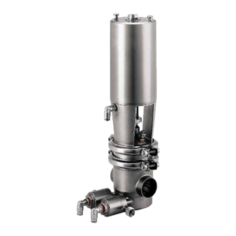
- Page 1 Instruction Manual SMP-BCA Aseptic Mixproof Valve with PTFE Diaphragm ESE02251-EN5 2022-10 Original manual...
-
Page 3: Table Of Contents
Table of contents The information herein is correct at the time of issue but may be subject to change without prior notice 1. Declarations of Conformity ..............2. Safety ..................2.1. Important information ................2.2. Warning signs ..................2.3. Safety precautions ................3. -
Page 4: Declarations Of Conformity
Declaration of of of Conformity Conformity Declaration Conformity The Designated Company Alfa Laval Kolding A/S, Albuen 31, DK-6000 Kolding, Denmark, +45 79 32 22 00 Company name, address and phone number Hereby declare that Sanitary Mixproof Valve Designation SMP-BC PN10... - Page 5 Declaration of of of Conformity Conformity Declaration Conformity The Designated Company Alfa Laval Kolding A/S, Albuen 31, DK-6000 Kolding, Denmark, +45 79 32 22 00 Company name, address and phone number Hereby declare that Sanitary Mixproof Valve Designation SMP-BC PN10...
-
Page 6: Safety
2 Safety Unsafe practices and other important information are emphasized in this manual. Warnings are emphasized by means of special signs. All warnings in the manual are summarized on this page. Pay special attention to the instructions below so that severe personal injury and/or damage to the valve are avoided. -
Page 7: Safety Precautions
2 Safety Unsafe practices and other important information are emphasized in this manual. Warnings are emphasized by means of special signs. All warnings in the manual are summarized on this page. Pay special attention to the instructions below so that severe personal injury and/or damage to the valve are avoided. -
Page 8: Installation
CAUTION! CAUTION! CAUTION! 1. Complete valve, standard or three-bodied valve. 2. Delivery note. Alfa Laval cannot be held responsible for incorrect unpacking. 3. Instruction manual. Step Step Step 2 2 2 Remove possible packing materials from the valve ports. Avoid... -
Page 9: Recycling Information
- At end of use, the equipment must be recycled according to the relevant, local regulations. Besides the equipment itself, any hazardous residues from the process liquid must be considered and dealt with in a proper manner. When in doubt, or in the absence of local regulations, please contact your local Alfa Laval sales company. 3.3 General installation... - Page 10 3 Installation Study the instructions carefully and pay special attention to the warnings! The valve has welding ends as standard but can also be supplied with fittings. CIP = Cleaning In Place (see section 4.3 Recommended cleaning). Step Step Step 3 3 3 Avoid stressing the valve.
- Page 11 3 Installation Study the instructions carefully and pay special attention to the warnings! The valve has welding ends as standard but can also be supplied with fittings. CIP = Cleaning In Place (see section 4.3 Recommended cleaning). Step Step Step 6 6 6 CIP/Steam connection connection : CIP/Steam...
-
Page 12: Welding
3 Installation Study the instructions carefully and pay special attention to the warnings! The valve has welding ends as standard. Weld carefully. Check the valve for smooth operation after welding. 3.4 Welding Step 1 1 1 Step Step Air! Never stick your fingers through the valve ports if the actuator is supplied with compressed air. -
Page 13: Operation
Step Step 1 1 1 CAUTION! CAUTION! CAUTION! Alfa Laval cannot be held responsible for incorrect operation. - Always read the technical data thoroughly (see 6.1 Technical data). - Always release compressed air after use. - Never touch the clip assembly or the actuator piston rod when the actuator is supplied with compressed air. -
Page 14: Recommended Cleaning
4 Operation The valve is designed for cleaning in place (CIP). CIP = Cleaning In Place. Study the instructions carefully and pay special attention to the warnings! NaOH = Caustic Soda. HNO3 = Nitric acid. 4.3 Recommended cleaning Step 1 1 1 Step Step Caustic... - Page 15 4 Operation The valve is designed for cleaning in place (CIP). CIP = Cleaning In Place. Study the instructions carefully and pay special attention to the warnings! NaOH = Caustic Soda. HNO3 = Nitric acid. Step Step Step 5 5 5 Recommended Recommended cleaning Recommended...
-
Page 16: Cleaning And Sterilization Equipment (Optional Extra)
4 Operation The installations kits are for cleaning/sterilizing of the leakage chamber when the valve is closed. The stainless steel tubes must be cut and welded during installation. CIP = Cleaning In Place. Step Step Step 10 Open Open Open Stop Stop Stop valve: valve:... -
Page 17: Maintenance
5 Maintenance Maintain the valve regularly. Study the instructions carefully and pay special attention to the warnings! CIP = Cleaning In Place. Always keep spare rubber seals, lip seals and guide rings in stock. 5.1 General maintenance Step Step Step 1 1 1 CAUTION! CAUTION! CAUTION! - Page 18 5 Maintenance Maintain the valve regularly. Study the instructions carefully and pay special attention to the warnings! CIP = Cleaning In Place. Always keep spare rubber seals, lip seals and guide rings in stock. The valve is designed so that single internal leakages do not resolve in the products becoming mixed. Internal leakage in the valve is externally visible.
-
Page 19: Dismantling Of Valve
5 Maintenance Study the instructions carefully. The items refer to the drawings and the parts list in chapter 7 Parts list and service kits. Lubricate the rubber seals and the diaphragms before fitting them. 5.2 Dismantling of valve Step Step Step 1 1 1 Change Change - - - over... -
Page 20: Assembly Of Valve
5 Maintenance Study the instructions carefully. The items refer to the drawings and the parts list in chapter 7 Parts list and service kits. Lubricate the rubber seals and the diaphragms before fitting them. Step Step Step 4 4 4 Change - - - over over valve valve... - Page 21 5 Maintenance Study the instructions carefully. The items refer to the drawings and the parts list in chapter 7 Parts list and service kits. Lubricate the rubber seals and the diaphragms before fitting them. Step Step Step 3 3 3 1.
- Page 22 5 Maintenance Study the instructions carefully. The items refer to the drawings and the parts list in chapter 7 Parts list and service kits. Lubricate the rubber seals and the diaphragms before fitting them. Step Step Step 7 7 7 Change - - - over over valve valve...
-
Page 23: Dismantling Of Actuator
5 Maintenance Study the instructions carefully. The items refer to the drawings and the parts list in chapter 7 Parts list and service kits. Handle scrap correctly. 5.4 Dismantling of actuator Step Step Step 1 1 1 Rotate with with the the service service Rotate... -
Page 24: Assembly Of Actuator
5 Maintenance Study the instructions carefully. The items refer to the drawings and the parts list in chapter 7 Parts list and service kits. Lubricate the rubber seals before fitting them. 5.5 Assembly of actuator Step 1 1 1 Step Step 1. -
Page 25: Replacement Of Plug Seals
5 Maintenance Study the instructions carefully. The items refer to the parts list and service kits - see section 7 Parts list and service kits. Handle scrap correctly. Do not not lubricate the rubber seals or the tool parts before fitting the seals. Step Step Step 5 5 5... - Page 26 5 Maintenance Study the instructions carefully. The items refer to the parts list and service kits - see section 7 Parts list and service kits. Handle scrap correctly. Do not not lubricate the rubber seals or the tool parts before fitting the seals. Step Step Step 2 2 2...
- Page 27 5 Maintenance Study the instructions carefully. The items refer to the parts list and service kits - see section 7 Parts list and service kits. Handle scrap correctly. Do not not lubricate the rubber seals or the tool parts before fitting the seals. Step Step Step 3 3 3...
- Page 28 5 Maintenance Study the instructions carefully. The items refer to the parts list and service kits - see section 7 Parts list and service kits. Handle scrap correctly. Do not not lubricate the rubber seals or the tool parts before fitting the seals. Step Step Step 4 4 4...
-
Page 29: Technical Data
Inform the personnel about the technical data. 6.1 Technical data SMP-BCA is operated by means of compressed air. The valve is a normally closed (NC) valve. Sterile stem sealing towards the atmosphere is ensured by a special designed PTFE/rubber diaphragm unit. The PTFE diaphragm does not allow product residues to build up on the product contact surface. - Page 30 6 Technical data It is important to observe the technical data during installation, operation and maintenance. Inform the personnel about the technical data. W W W eight eight eight (kg) 63.5 76.1 101.6 63.5 63.5 76.1 76.1 101.6 101.6 Size Size Size Weight - Stop valve...
-
Page 31: Parts List And Service Kits
7 Parts list and service kits It is important to observe the technical data during installation, operation and maintenance. Inform the personnel about the technical data. (76-101.6mm/DN80-100) CIP/detecting valve... -
Page 32: Stop Valve
7 Parts list and service kits It is important to observe the technical data during installation, operation and maintenance. Inform the personnel about the technical data. Stop valve... - Page 33 7 Parts list and service kits It is important to observe the technical data during installation, operation and maintenance. Inform the personnel about the technical data. Change-over valve...
- Page 34 7 Parts list and service kits It is important to observe the technical data during installation, operation and maintenance. Inform the personnel about the technical data. 7.1 Stop valve � Sizes 76-101.6 mm/DN80-100...
- Page 35 7 Parts list and service kits It is important to observe the technical data during installation, operation and maintenance. Inform the personnel about the technical data. Parts Parts Parts list list list Pos. Denomination Actuator complete O-ring � Plug Cylinder Spring assembly Lock wire �...
- Page 36 7 Parts list and service kits It is important to observe the technical data during installation, operation and maintenance. Inform the personnel about the technical data. Service Service Service kits kits kits 38 mm 51 mm 63.5 63.5 mm 63.5 76.1 76.1 76.1 mm...
-
Page 38: Change-Over Valve
7 Parts list and service kits It is important to observe the technical data during installation, operation and maintenance. Inform the personnel about the technical data. 7.2 Change-over valve � Sizes 76-101.6 mm/DN 80-100... - Page 39 7 Parts list and service kits It is important to observe the technical data during installation, operation and maintenance. Inform the personnel about the technical data. Parts Parts Parts list list list Pos. Denomination Actuator complete O-ring � Plug Cylinder Spring assembly Lock wire �...
- Page 40 7 Parts list and service kits It is important to observe the technical data during installation, operation and maintenance. Inform the personnel about the technical data. Service Service Service kits kits kits 38 mm 51 mm 63.5 63.5 mm 63.5 76 mm 101.6 101.6 mm...
-
Page 42: Tool For Plug Seals
7 Parts list and service kits It is important to observe the technical data during installation, operation and maintenance. Inform the personnel about the technical data. 7.3 Tool for plug seals Tool for shut-off valve and change-over valve (upper plug) Small seal ring Large seal ring * Only for 38-51 mm/DN40-50 upper... - Page 43 7 Parts list and service kits It is important to observe the technical data during installation, operation and maintenance. Inform the personnel about the technical data. Parts Parts Parts list list list Pos. Denomination Outer guide ring for large seal Pin for tool Inner guide ring for large seal Tool housing, upper plug...
- Page 44 © Alfa Laval Corporate AB This document and its contents is owned by Alfa Laval Corporate AB and protected by laws governing intellectual property and thereto related rights. It is the responsibility of the user of this document to comply with all applicable intellectual property laws. Without limiting any rights related to this document, no part of this document may be copied, reproduced or transmitted in any form or by any means (electronic, mechanical, photocopying, recording, or otherwise), or for any purpose, without the expressed permission of Alfa Laval Corporate AB.
Need help?
Do you have a question about the SMP-BCA and is the answer not in the manual?
Questions and answers