Alfa Laval SMP-BC Instruction Manual
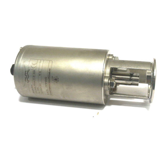
Sanitary mixproof valve
Hide thumbs
Also See for SMP-BC:
- Instruction manual (36 pages) ,
- Instruction manual (48 pages) ,
- Instruction manual (61 pages)

Related Manuals for Alfa Laval SMP-BC


Summary of Contents for Alfa Laval SMP-BC
- Page 1 Instruction Manual SMP-BC Sanitary Mixproof Valve TD 430-147_1 ESE02255-EN7 2016-06 Original manual...
-
Page 3: Table Of Contents
6. Technical data ..................6.1. Technical data ..................7. Parts list and service kits ................7.1. Drawings ................... 7.2. SMP-BC stop valve ................7.3. SMP-BC change-over valve ..............7.4. SMP-BC stop valve - size DN125/DN150 ............. 7.5. Tools for plug seals ................ -
Page 4: Ec Declaration Of Conformity
1 EC Declaration of Conformity Revision of Declaration of Conformity 2009-12-29 The Designated Company Alfa Laval Kolding A/S Company Name Albuen 31, DK-6000 Kolding, Denmark Address +45 79 32 22 00 Phone No. hereby declare that Sanitary Mixproof Valve Designation... -
Page 5: Safety
2 Safety Unsafe practices and other important information are emphasized in this manual. Warnings are emphasized by means of special signs. All warnings in the manual are summarized on this page. Pay special attention to the instructions below so that severe personal injury and/or damage to the valve are avoided. 2.1 Important information Important information Always read the manual before using the valve! -
Page 6: Safety Precautions
2 Safety Unsafe practices and other important information are emphasized in this manual. Warnings are emphasized by means of special signs. All warnings in the manual are summarized on this page. Pay special attention to the instructions below so that severe personal injury and/or damage to the valve are avoided. 2.3 Safety precautions Installation: Always read the technical data thoroughly (see chapter 6 Technical data) -
Page 7: Installation
Check the delivery for: CAUTION! 1. Complete valve, standard or three-bodied valve 2. Delivery note Alfa Laval cannot be held responsible for incorrect unpacking. 3. Instruction manual Step 2 Remove possible packing materials from the valve ports. Avoid damaging the air connection, the valve ports, the detecting valve Caution! and the CIP valve. -
Page 8: Recycling
- At end of use, the equipment must be recycled according to the relevant, local regulations. Besides the equipment itself, any hazardous residues from the process liquid must be considered and dealt with in a proper manner. When in doubt, or in the absence of local regulations, please contact your local Alfa Laval sales company... -
Page 9: Recommended Auxiliary Equipment (Dn125/150)
3 Installation The valve sizes DN125-150 are very heavy. Therefore Alfa Laval recommends manufacturing and usage of auxiliary equipment. A proposal is given below. Please note that the auxiliary equipment cannot be supplied by Alfa Laval. The items refers to the drawings, parts list and service kits, see chapter 7 Parts list and service kits 3.3 Recommended auxiliary equipment (DN125/150) -
Page 10: General Installation
- Always release compressed air after use. - Never touch the clip assembly or the actuator piston rod if the actuator is supplied with compressed air. CAUTION! Alfa Laval cannot be held responsible for incorrect installation. Step 2 Stop valve... -
Page 11: Welding
3 Installation Study the instructions carefully and pay special attention to the warnings. The valve has welding ends as standard. Weld carefully. Check the valve for smooth operation after welding. Step 5 R1/8”(BSP) (additional air supply) Air connection: R1/8”(BSP) Step 6 CIP connection: 1. - Page 12 3 Installation Study the instructions carefully and pay special attention to the warnings. The valve has welding ends as standard. Weld carefully. Check the valve for smooth operation after welding. Step 2 Dismantle the valve in accordance with steps 1-3, section 5.2 Dismantling of valve Pay special attention to the warnings! Step 3...
- Page 13 3 Installation Study the instructions carefully and pay special attention to the warnings. The valve has welding ends as standard. Weld carefully. Check the valve for smooth operation after welding. Step 5 Pre-use check: 1. Supply compressed air to the actuator. 2.
-
Page 14: Operation
). air. Always release compressed air after use. CAUTION! Alfa Laval cannot be held responsible for incorrect operation. Step 2 Never touch the valve or the pipelines when processing hot liquids or when sterilizing. -
Page 15: Recommended Cleaning
4 Operation The valve is designed for cleaning in place (CIP) Study the instructions carefully and pay special attention to the warnings! NaOH = Caustric soda = Nitric acid 4.3 Recommended cleaning Step 1 Caustic danger! Always handle lye and acid with great care. Always use Always use rubber gloves! - Page 16 4 Operation The valve is designed for cleaning in place (CIP) Study the instructions carefully and pay special attention to the warnings! NaOH = Caustric soda = Nitric acid Step 4 Examples of cleaning agents: Use clean water, free from chlorides. 1.
- Page 17 4 Operation The valve is designed for cleaning in place (CIP) Study the instructions carefully and pay special attention to the warnings! NaOH = Caustric soda = Nitric acid Step 9 Open stop valve: Cleaning of the valve body and the leakage chamber A = CIP TD 430-044_1 Step 10...
-
Page 18: Cleaning Equipment (Optional Extra)
4 Operation The installation kits are for cleaning of the leakage chamber when the valve is closed. The combination of the different kits depends on the actual applications. CIP = Cleaning In Place 4.4 Cleaning equipment (optional extra) Step 1 Installation kit A for CIP and leakage connections of a single valve (PVDF/stainless steel tubes) Contents: Pos. - Page 19 4 Operation The installation kits are for cleaning of the leakage chamber when the valve is closed. The combination of the different kits depends on the actual applications. CIP = Cleaning In Place Step 3 Installation kit C for CIP and leakage connection of a single valve (stainless steel tubes) Contents: Pos.
-
Page 20: Maintenance
5 Maintenance Maintain the valve regularly. Study the instructions carefully and pay special attention to the warnings! CIP = Cleaning In Place. Always keep spare rubber seals, lip seals and guide rings in stock. 5.1 General maintenance Step 1 - Always read the technical data thoroughly (see 6 Technical CAUTION! data). - Page 21 5 Maintenance Maintain the valve regularly. Study the instructions carefully and pay special attention to the warnings! CIP = Cleaning In Place. Always keep spare rubber seals, lip seals and guide rings in stock. The valve is designed so that single internal leakages do not result in the products becoming mixed. Internal leakage in the valve is externally visible.
-
Page 22: Dismantling Of Valve
5 Maintenance Stude the instructions carefully. The items refer to the parts list and service kits section - see chapter 7 Parts list and service kits . Handle scrap correctly. Removal of plug seals, please see the special instructions, section 5.6 Replacement of plug seals. Top view Water 3-4 bar Pre-use check... - Page 23 5 Maintenance Stude the instructions carefully. The items refer to the parts list and service kits section - see chapter 7 Parts list and service kits . Handle scrap correctly. Removal of plug seals, please see the special instructions, section 5.6 Replacement of plug seals. Step 3 1.
-
Page 24: Assembly Of Valve
5 Maintenance Study the instructions carefully. The items refer to the parts list and service kits section. Lubricate the rubber seals and the lip seal before fitting them. Fitting of plug seals, please see the special instructions, see section 5.6 Replacement of plug seals 5.3 Assembly of valve Step 1 1. -
Page 25: Dismantling Of Actuator
5 Maintenance Study the instructions carefully. The imtes refer to the parts list and service kits section. Handle scrap correctly. Step 5 Change-over valve: 1. Fit upper ring (27) in middle valve body (28). 2. Position the middle valve body on upper valve body (25). 3. - Page 26 5 Maintenance Study the instructions carefully. The imtes refer to the parts list and service kits section. Handle scrap correctly. Step 2 1. Disconnect cylinder (5) from bonnet (16). 2. Pull off o-ring (13) from the bonnet. Step 3 1. Pull out piston (11) and spring packet (6). 2.
-
Page 27: Assembly Of Actuator
5 Maintenance Study the instructions carefully. The items refer to the parts list and service kits section. Lubricate the rubber seals before fitting them. 5.5 Assembly of actuator Step 1 Fit lip seal (20) in bonnet (16) (DN125/DN150). Step 2 Fit guide ring (17) in bonnet (16). - Page 28 5 Maintenance Study the instructions carefully. The items refer to the parts list and service kits section. Lubricate the rubber seals before fitting them. Step 5 Rotate by hand or with 1. Rehook lock wire (7) through the slot in cylinder (5) in the hole the service tool! in bonnet (16).
-
Page 29: Replacement Of Plug Seals
5 Maintenance Study the instructions carefully. The items refer to the parts list and service kits section. Handle scrap correctly. Do not lubricate the rubber seals or the tool parts before fitting the seals. 5.6 Replacement of plug seals Step 1 Removing the seal rings Remove the old seal rings by cutting them through and pulling them out of the grooves. - Page 30 5 Maintenance Study the instructions carefully. The items refer to the parts list and service kits section. Handle scrap correctly. Do not lubricate the rubber seals or the tool parts before fitting the seals. Step 2 Fitting the seal rings (For stop and change-over valves). Lower (small) seal ring.
- Page 31 5 Maintenance Study the instructions carefully. The items refer to the parts list and service kits section. Handle scrap correctly. Do not lubricate the rubber seals or the tool parts before fitting the seals. Step 3 Fitting the seal rings (for stop and change-over valves) Upper (large) seal ring 1.
- Page 32 5 Maintenance Study the instructions carefully. The items refer to the parts list and service kits section. Handle scrap correctly. Do not lubricate the rubber seals or the tool parts before fitting the seals. Step 4 Fitting the seal rings (for change-over valves) 1.
-
Page 33: Technical Data
6.1 Technical data SMP-BC is remote-controlled by means of compressed air. The valve is a normally closed (NC) valve. The valve is fitted with two small pneumatic normally open (NO) valves, a detecting valve and a CIP-valve. The valve plug (the upper plug in a change-over valve) has two seals, forming a leakage chamber under atmospheric pressure between them. -
Page 34: Parts List And Service Kits
7.1 Drawings CIP/detecting valve (period 9304-9504) The drawing show SMP-BC stop valve, change-over valve CIP/detecting valve (period 9505-) The drawing show SMP-BC stop valve, change-over valve and stop valve sixes DN125/DN150 Stem seal The drawing show SMP-BC stop valve, change-over valve... - Page 35 7 Parts list and service kits The items refer to the parts lists in the following sections. Stop valve Change-over valve...
-
Page 36: Smp-Bc Stop Valve
7 Parts list and service kits The items refer to the parts lists in the following sections. 7.2 SMP-BC stop valve TD 430-149_2 * = CIP/detecting valve. ** = CIP/detecting valve. Diam. ø32. Diam. ø27. (Period 9505- ) (Period 9304-9504) - Page 37 7 Parts list and service kits The items refer to the parts lists in the following sections. Parts list Pos. Denomination O-ring Plug Cylinder Spring packet Lock wire O-ring Piston Clip, complete O-ring Air fitting, swivel tee Bonnet ...
-
Page 38: Smp-Bc Change-Over Valve
7 Parts list and service kits The items refer to the parts lists in the following sections. 7.3 SMP-BC change-over valve TD 430-151_2 CIP/detecting valve. CIP/detecting valve. Diam. ø32. Diam. ø27. (Period 9505- ) (Period 9304-9504) - Page 39 7 Parts list and service kits The items refer to the parts lists in the following sections. Parts list Pos. Denomination O-ring Plug Cylinder Spring packet Lock wire O-ring Piston Clip, complete O-ring Air fitting, swivel tee Bonnet ...
- Page 40 7 Parts list and service kits The items refer to the parts lists in the following sections. Service kits DN 40 DN 50 DN65 DN 80 DN 100 Denomination 38 mm 51 mm 63.5 mm 76 mm 101.6 mm Service Kit for Actuator, detecting / CIP-valve ø32 ...
-
Page 42: Smp-Bc Stop Valve - Size Dn125/Dn150
7 Parts list and service kits The items refer to the parts lists in the following sections. 7.4 SMP-BC stop valve - size DN125/DN150 TD 430-150_2 CIP/detecting valve. Diam. ø32. - Page 43 7 Parts list and service kits The items refer to the parts lists in the following sections. Parts list Pos. Denomination Actuator, complete O-ring Guide ring Plug Cylinder Spring packet Lock wire Guide ring O-ring Top pin Piston ...
-
Page 44: Tools For Plug Seals
7 Parts list and service kits The items refer to the parts lists in the following sections. 7.5 Tools for plug seals Tool for shut-off valve and change-over valve (upper plug) 13** 13** 2309-0010 2309-0011 Small seal ring Large seal ring * = Only for 38-51 mm/DN40-50 upper change-over plug (marking C8) ** = Only for DN125/150 Tool for change-over valve (lower plug). - Page 45 7 Parts list and service kits The items refer to the parts lists in the following sections. Parts list Pos. Denomination Outer guide ring for large seal Pin for tool Inner guide ring for large seal Tool housing, upper plug Outer guide ring for small seal Inner guide ring for small seal Support part, upper plug...
- Page 46 © Alfa Laval Corporate AB This document and its contents is owned by Alfa Laval Corporate AB and protected by laws governing intellectual property and thereto related rights. It is the responsibility of the user of this document to comply with all applicable intellectual property laws. Without limiting any rights related to this document, no part of this document may be copied, reproduced or transmitted in any form or by any means (electronic, mechanical, photocopying, recording, or otherwise), or for any purpose, without the expressed permission of Alfa Laval Corporate AB.
Need help?
Do you have a question about the SMP-BC and is the answer not in the manual?
Questions and answers