Table of Contents
Advertisement
Quick Links
Advertisement
Table of Contents

Related Manuals for Xytronix Research & Design ControlByWeb X317


Summary of Contents for Xytronix Research & Design ControlByWeb X317
- Page 2 X-317™ Users Manual X-317 User Manual Revisions Revision Description Initial release Minor grammatical cleanup Changed Modbus addressing Page 2 Xytronix Research & Design, Inc.
-
Page 3: Table Of Contents
X-317™ Users Manual Table of Contents Section 1: Introduction............................6 1.1 Features..............................7 1.1.1 X-317™ Features:..........................7 1.1.2 Digital to Analog Converter......................... 7 1.2 Connectors & Indicators......................... 8 1.3 Accessing the X-317..........................9 1.4 Part Numbers and Accessories......................9 Section 2: Installation and Connections ......................10 2.1 Installation Guidelines.......................... - Page 4 X-317™ Users Manual 5.3.2 PLC Device Addressing........................44 5.3.3 X-317 Modbus Address Table......................45 5.3.4 Read Holding Registers – Modbus Function Code 03 (0x03)............46 5.3.4.1 Request............................. 46 5.3.4.2 Response..........................46 5.3.4.3 Errors............................47 5.3.5 Write Multiple Registers (Modbus Function Code 16 (0x10))............48 5.3.5.1 Request.............................
- Page 5 X-317™ Users Manual Limitation........................66 Appendix I: FCC Statement..........................67 Warning........................67 Notice........................... 67 Section 6: J: Mechanical Dimensions......................68 Xytronix Research & Design, Inc. Page 5...
-
Page 6: Section 1: Introduction
Introduction X-317™ Users Manual Section 1: Introduction The X-317™ is a web-enabled analog output module with five output channels. It combines many of the features found on other ControlByWeb products and adds new capabilities to the product line. Each channel can be programmed to output a voltage or current. The analog outputs are similar to that of a Programmable Logic Controller (PLC). -
Page 7: Features
X-317™ Users Manual Introduction 1.1 Features 1.1.1 X-317™ Features: • Five separate analog output channels • 0-5V, 0-10V, ±5V, ±10V, 4-20mA output ranges • Outputs are software configured, independently programmable and scalable • Built in isolated DC-DC converter • Wide power supply range (9-28VDC) •... -
Page 8: Connectors & Indicators
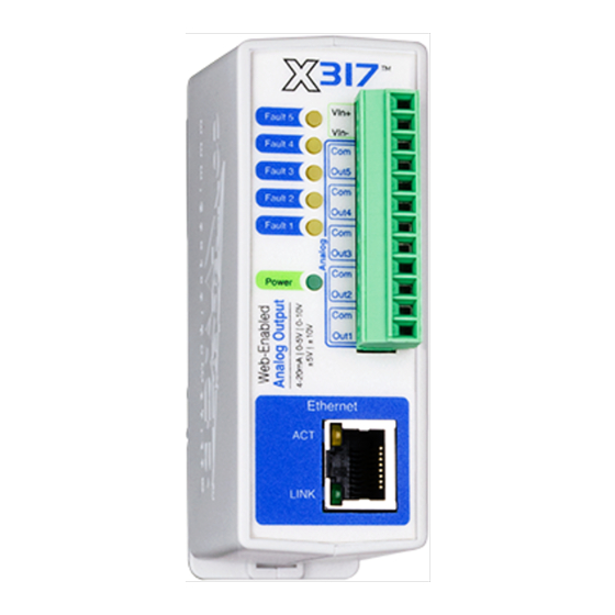
Introduction X-317™ Users Manual 1.2 Connectors & Indicators Connections & Indicators I/O Connector The 12-pin terminal connector is used to provide power to the module and connect the Analog Outputs. Network Connector The Ethernet connector is a standard, 8-position modular receptacle. Module Power Indicator The green Power LED indicator is illuminated whenever the module is powered. -
Page 9: Accessing The X-317
X-317™ Users Manual Introduction Ethernet Indicators The green LINK LED is illuminated when the module is properly connected to an Ethernet network and is ready to communicate. Network communications will only occur if this LED is illuminated. The ACT LED flashes amber when activity is detected on the network. 1.3 Accessing the X-317 Standard Access Using a Web Browser The X-317™... -
Page 10: Section 2: Installation And Connections
Installation and Connections X-317™ Users Manual Section 2: Installation and Connections Installation consists of mounting the X-317, connecting it to an Ethernet network, providing power, wiring the analog outputs, and configuring via a web browser. 2.1 Installation Guidelines • This unit must be installed by qualified personnel. In the case of line-voltage connections, a licensed electrician should be employed. -
Page 11: Mounting
X-317™ Users Manual Installation and Connections 2.4 Mounting The X-317 can be mounted to a standard (35mm by 7.55mm) DIN-Rail. The X-317 should be located in a clean, dry location where it is protected from the elements. Ventilation is recommended for installations where ambient air temperatures are expected to be high. -
Page 12: Power Supply Connections
Installation and Connections X-317™ Users Manual ● Make sure wires are properly attached to the terminals and that the terminals are tight! ● Do not route signal cables in the same conduit or raceway with AC power lines feeding motors, solenoids or other electrically noisy loads. -
Page 13: Analog Output Connections
X-317™ Users Manual Installation and Connections 2.5.2 Analog Output Connections The analog outputs can be individually programmed to function as 0-5V, 0-10V, ±5V, ±10V, 4-20mA outputs. Voltage Output Connections Many variable frequency drives (VFD), servos and other actuators are controlled by a variable voltage. To use these devices the Aout and Com outputs are connected directly to the device to be controlled. -
Page 14: Network Connection
Installation and Connections X-317™ Users Manual 2.5.3 Network Connection Connect the Ethernet port to a 10 Base-T or 10/100 Base-T Ethernet connection. This typically connects to an Ethernet hub, switch, or router. For configuration, the X-317 may be connected directly to the Ethernet port on a computer using a “crossover”... -
Page 15: Establishing Communications For Setup
X-317™ Users Manual Installation and Connections 2.6 Establishing Communications for Setup In order to configure the X-317 with the web browser interface, the X-317 must be connected to an Ethernet computer network. This can be done by one of two methods: Method 1–... - Page 16 Installation and Connections X-317™ Users Manual 4. Select View network status and tasks. 5. Select Change adapter settings Page 16 Xytronix Research & Design, Inc.
- Page 17 X-317™ Users Manual Installation and Connections 6. Your machine may have more than one Internet connection shown. Right-click on the adapter for your connection to the internet. A drop down box will appear, choose Properties to view/edit the settings for this internet connection. 7.
- Page 18 Installation and Connections X-317™ Users Manual 8. If “Use the following IP address” is already selected, the computer has been setup with a static IP address. Record these values so that the current IP address of the computer can be restored once the IP address of the X-317 has been successfully changed.
-
Page 19: Method 2: Assign A Temporary Ip Address To The X-317
X-317™ Users Manual Installation and Connections 2.6.2 Method 2: Assign a Temporary IP address to the X-317 This option (arping) is used to TEMPORARILY assign an IP address to the X-317 without the need to change the IP address of the configuration computer. The X-317 will use this IP address as long as power is maintained. -
Page 20: Mac Os X Instructions
Installation and Connections X-317™ Users Manual 4. Proceed with the X-317 setup in section 4. Once setup is complete, it may be necessary to clear the 'arp' cache to configure additional devices. This is necessary because each unit has the same default IP address, but a different unit serial number (MAC address). -
Page 21: Section 3: Example Applications
X-317™ Users Manual Example Applications Section 3: Example Applications The X-317 was designed to meet a broad range of industrial and scientific applications including: Process Control The X-317 may be suitable for process control applications where a PLC is typically used or to augment PLC capabilities. -
Page 22: Manual Control
Example Applications X-317™ Users Manual Manual Control You can manually control a device over the internet without using a PLC or other complicated interface. With the X-317 you can access its internal web page and manually control the outputs. The example below shows how to control a conveyor motor from a web page without using SCADA software or a PLC. -
Page 23: Section 4: Configuration And Setup
X-317™ Users Manual Configuration and Setup Section 4: Configuration and Setup 4.1 X-317 Setup Pages The X-317 is configured using a web browser. To access the setup pages, enter the following URL in the address bar of a web browser: http://{ipaddress}/setup.html For example, using the default IP address, enter: http://192.168.1.2/setup.html... -
Page 24: Network Tab
Configuration and Setup X-317™ Users Manual 4.1.2 Network Tab The network parameters are set on this page. Note: The X-317 must be power-cycled (power disconnected, then reconnected) before network settings take effect. Only the settings on the Network tab require power-cycling before taking effect. Use DHCP This option allows DHCP to be enabled or disabled. - Page 25 X-317™ Users Manual Configuration and Setup does not change. The X-317 is a server and manual IP address assignment is usually recommended. IP Address Enter the IP address for the X-317 in this field. The IP address is specific to the network where the X-317 will be installed, and must be obtained from the network administrator.
-
Page 26: Advanced Network Tab
Configuration and Setup X-317™ Users Manual 4.1.3 Advanced Network Tab Note: These settings are not used for most installations. Modbus Enabled The X-317 can support Modbus/TCP. Modbus is a messaging structure protocol used in industrial manufacturing control and automation. It is an open protocol and offers interoperability with software and devices from other manufacturers. - Page 27 X-317™ Users Manual Configuration and Setup enter it in this format aaa.bbb.ccc.ddd. For numbers that are less than 100, preceding zeros should not be included (for example, enter 80 rather than 080). This field can be up to 40 characters long and has no default setting.
- Page 28 Configuration and Setup X-317™ Users Manual Remote Services Remote Services initiates an outgoing connection to a server at a remote location. This can be used in an environment where a web server on the Internet provides a custom web page to the X-317 and other ControlByWeb products.
-
Page 29: Password Tab
X-317™ Users Manual Configuration and Setup 4.1.4 Password Tab The X-317 requires a password to log into the setup pages. The password can be changed on this page. Additionally, the installer can enable the requirement for a Control Page password. Setup Password The Setup Password, which is required to access the setup pages, can be modified by entering a new password here. -
Page 30: Analog Outputs Tab
Configuration and Setup X-317™ Users Manual 4.1.5 Analog Outputs Tab This page provides configuration options for each of the five analog outputs. After making selections for a particular output channel you must click the Submit button to save your work before selecting another channel for further edits. - Page 31 X-317™ Users Manual Configuration and Setup Page display descriptive and easy to use. The units settings are for display only and are not used in the calculations for setting the digital to analog converter. Decimal Places This setting determines how many digits are shown to the right of the decimal point for the data values shown on the Control Page.
- Page 32 Configuration and Setup X-317™ Users Manual To restore the default settings so that no data scaling is done set the User Input Max to the maximum D/A output voltage and the User Input Min to the minimum D/A output voltage. Make the user input and the D/A output values the same for both data points as shown in the table below: Settings for no data scaling (1:1) Mode...
-
Page 33: Script Tab
X-317™ Users Manual Configuration and Setup 4.1.6 Script Tab The X-317 can be used to run simple custom programs written in a language similar to BASIC. This page is used to load and execute these programs. Before it can be loaded to the X-317, a script must first be written as a .txt file. - Page 34 Configuration and Setup X-317™ Users Manual Upload BASIC Script This field displays the script selected to be uploaded to the device. To upload a script to the X-317, click the 'Choose File' button, find the .txt file previously written, and select 'Open.' The location of the file should appear in the neighboring field.
- Page 35 X-317™ Users Manual Configuration and Setup Description Text entered here will be displayed in the left column of the control page. Up to 24 characters may be entered here. The default text is extVar#. Button 1 Label This text field is used to describe the function of button 1 of the selected extVar. The text also appears to the right of the corresponding extVar status.
-
Page 36: Control Page Setup Tab
Configuration and Setup X-317™ Users Manual 4.1.7 Control Page Setup Tab The Control Page Setup page is used mainly to make settings that affect how the Control Page is displayed and how often it will refresh, etc. Main Header Text The text entered here appears at the top of the Control Page. - Page 37 X-317™ Users Manual Configuration and Setup Display Configurations: These settings affect the user Control Page format. Certain settings omit the “set” box to prevent specific channels from be changed via the Control Page. For the check box settings in the example above the following control page will be shown: Analog-1: Analog value not displayed, edit box is not displayed (suppressed)
-
Page 38: Section 5: Operation
Operation X-317™ Users Manual Section 5: Operation The X-317 can be operated using a web browser, by sending text commands to an XML status/control page, and/or by sending Modbus/TCP requests. 5.1 Browser Operation Once the X-317 is set up, users can access the Control Page using a web browser by typing the IP address of the X-317 into the web browser address bar. - Page 39 X-317™ Users Manual Operation Header Displays the text entered in the Main Header Text field on the Control Page Setup tab in the setup pages. Output 1-5 These rows display the current state of the five analog outputs and allow the user to set (change) the output value.
-
Page 40: Xml Operation
Operation X-317™ Users Manual 5.2 XML Operation Custom XML computer applications may be created to monitor and control the X-317. This method does not use a web browser. Diagnostics.xml is available for troubleshooting and system monitoring. With XML, the analog output values are the “user units” values which are subsequently processed by the Y=mX+b equation to drive the digital to analog converter. -
Page 41: Xml Control
X-317™ Users Manual Operation 5.2.2 XML Control Commands can be sent to the X-317 to control the analog outputs. Each analog output can be controlled individually. The following are a few examples: Command Description state.xml?an1State=0 Set channel 1 to 0.0 state.xml?an1State=2.5 Set channel 1 to 2.5 state.xml?an2State=50... -
Page 42: Xml Diagnostics
Operation X-317™ Users Manual 5.2.4 XML Diagnostics There is a special diagnostics.xml page that can be requested by entering the following in the web browser address bar: http://192.168.1.2/diagnostics.xml The following diagnostics.xml file is returned. <datavalues> <devicePowerUpFlag>1</devicePowerUpFlag> </datavalues> Diagnostic tags are given in the table below. Description <devicePowerUpFlag>... -
Page 43: Modbus Operation
X-317™ Users Manual Operation 5.3 Modbus Operation The X-317 can be controlled and monitored using Modbus/TCP protocol. This provides a standard means of using the X-317 with devices and software from other manufacturers. This section is not a tutorial on Modbus and it is assumed that the reader is already familiar with Modbus. Detailed Modbus information can be found at http://www.modbus.org. -
Page 44: Plc Device Addressing
Operation X-317™ Users Manual 5.3.2 PLC Device Addressing There are generally two schemes for accessing Modbus devices, The first is by specifying the Modbus function code, memory type, and address. The second, sometimes called PLC addressing, requires only the address. Modbus protocol uses four different address ranges for discrete inputs, coils, input registers, and holding registers. -
Page 45: X-317 Modbus Address Table
X-317™ Users Manual Operation 5.3.3 X-317 Modbus Address Table The table below gives commonly used function code, memory type, data size, and equivalent PLC addresses for accessing the X-317. The data size will be the same regardless of the addressing mode. Function Address Data Size... -
Page 46: Read Holding Registers - Modbus Function Code 03 (0X03)
Operation X-317™ Users Manual 5.3.4 Read Holding Registers – Modbus Function Code 03 (0x03) The Read Holding Registers function is used to read the analog output values. 32-bit values are read from 16-bit register pairs. Consequently, the addresses and registers must be even numbers. 5.3.4.1 Request Modbus TCP Request Frame Example –... -
Page 47: Errors
X-317™ Users Manual Operation 5.3.4.3 Errors Error Response Frame Example Field Name Length Function Example Data Transaction Identifier 2 bytes Synchronization between messages of 0x0001 server and client. 0x0000 Protocol Identifier 2 bytes Zero for Modbus/TCP Message Length 2 bytes Number of bytes in frame (below) 0x0003 0xFF... -
Page 48: Write Multiple Registers (Modbus Function Code 16 (0X10))
Operation X-317™ Users Manual 5.3.5 Write Multiple Registers (Modbus Function Code 16 (0x10)) The Write Multiple Registers function is used to write (set) the analog output value(s). 32-bit values are written to 16-bit register pairs. Consequently, addresses and registers must be even numbers. -
Page 49: Errors
X-317™ Users Manual Operation 5.3.5.3 Errors Error Response Frame Example Field Name Length Function Example Data Transaction Identifier 2 bytes Synchronization between messages of 0x0001 server and client. 0x0000 Protocol Identifier 2 bytes Zero for Modbus/TCP Message Length 2 bytes Number of bytes in frame (below) 0x0003 0xFF... -
Page 50: Appendix A: Restoring Factory Default Settings
Appendix A: Restoring Factory Default Settings X-317™ Users Manual Appendix A: Restoring Factory Default Settings In the event that the IP address or passwords are forgotten, the X-317 may be restored to its original factory default settings. 1. Remove the DC power from the unit. 2. -
Page 51: Appendix B: Installing New Firmware
X-317™ Users Manual Appendix B: Installing New Firmware Appendix B: Installing New Firmware From time to time, updates are made to the X-317 firmware. The firmware can be updated in the field. The procedure for updating the firmware is outlined below. Please note that it is important that this procedure is followed precisely. - Page 52 Appendix B: Installing New Firmware X-317™ Users Manual Device Upgrade Procedure Carefully follow the following steps to put the X-317 into bootloader mode and perform the upgrade. Make a note of the current settings. The device will be reset to factory defaults after the upgrade. 1.
-
Page 53: Appendix C: Accessing The X-317 Over The Internet
X-317™ Users Manual Appendix C: Accessing the X-317 Over the Internet Appendix C: Accessing the X-317 Over the Internet The X-317 can be monitored and/or controlled from a remote location over the Internet. Once the X-317 can be accessed on the local network, almost all of the settings required to provide remote access are in the router and not in the X-317. - Page 54 Appendix C: Accessing the X-317 Over the Internet X-317™ Users Manual Local Area Network A Simple LAN connected to the Internet The LAN in the example above can be connected to the Internet by adding a router and an Internet connection.
- Page 55 X-317™ Users Manual Appendix C: Accessing the X-317 Over the Internet In the example, when a user on the computer needs to access a server on the Internet, the computer sends the request to the router at 192.168.1.1. The router sends the request to the ISP server on the Internet.
- Page 56 Appendix C: Accessing the X-317 Over the Internet X-317™ Users Manual Port Range Forwarding Note: This screen shot is simply an example of a typical router setup page. Routers will vary. Accessing Setup Pages After changing ports, the setup pages are accessed on a local network as described below: http://(Local IP Address):(Port Number)/setup.html For example, to access the setup pages when the port is set to 8000, the following command would be used:...
-
Page 57: Appendix D: Basic Scripts
X-317™ Users Manual Appendix D: BASIC Scripts Appendix D: BASIC Scripts BASIC (Beginners All-purpose Symbolic Instruction Code) is a computer programming language that has been in use for many years. The X-317 has an integrated BASIC interpreter for simple BASIC scripts. -
Page 58: Let
Appendix D: BASIC Scripts X-317™ Users Manual Supported Statements The following are the statements supported by the ControlByWeb™ BASIC interpreter. The LET statement assigns a variable a value. The format is: LET (variable) = (expression) IF THEN, ELSE, END IF The IF THEN statement tests the truth of a condition. -
Page 59: Rem Or
X-317™ Users Manual Appendix D: BASIC Scripts sensitive. The SUB and END SUB statements always must follow the END statement. The format is: '*** Subroutines Go Here *** SUB (name of subroutine) (contents of subroutine) END SUB SUB (name of subroutine) (contents of subroutine) END SUB REM or '... - Page 60 Appendix D: BASIC Scripts X-317™ Users Manual the Analog Outputs tab have been set for a 1 to 1 output relationship (no scaling). This allows the BASIC calculations and output settings to be in engineering units. For example: Let ana1 = 0 'set analog output 1 to 0.0V Let ana2 = 2.5 'set analog output 2 to +2.5V...
-
Page 61: Appendix E: External Server And Remote Services
X-317™ Users Manual Appendix E: External Server and Remote Services Appendix E: External Server and Remote Services Note: The following methods are supported by the X-317; however, Xytronix Research & Design, Inc. does not provide or support custom third party applications, or external web servers. Accessing the X-317 with Custom Software or Third Party Applications Custom applications can send commands to the X-317 for monitoring and control. - Page 62 Appendix E: External Server and Remote Services X-317™ Users Manual need to be opened in the router, security is not compromised. See section Advanced Network Tab for more information.. Connection String With Remote Services enabled, a connection attempt will be made periodically according to the Connection Interval setting in the Advanced Network setup tab.
-
Page 63: Appendix F: Specifications
X-317™ Users Manual Appendix F: Specifications Appendix F: Specifications Power Requirements Input Voltage: 9-28 VDC Current: See table below for typical values at 25°C 10 Mbps Network Speed Power Supply Outputs = 0V Outputs = 20mA 9 VDC 210 mA 404 mA 12 VDC 162 mA... -
Page 64: Led Indicators
Appendix F: Specifications X-317™ Users Manual LED Indicators Green: Power On Yellow: Fault condition, 5ea (channels 1-5), indicate output failure Network • 10 Base-T or 100 Base-T Ethernet IPv4 • Setup: Static IP address assignment or DHCP, HTTP port selectable •... -
Page 65: Appendix G: Trademark And Copyright Information
X-317™ Users Manual Appendix G: Trademark and Copyright Information Appendix G: Trademark and Copyright Information This document is Copyright ©2015 by Xytronix Research & Design, Inc. All rights reserved. X-317™, X-600M™, WebRelay™, ControlByWeb™, and Xytronix Research & Design™ are trademarks of Xytronix Research &... -
Page 66: Appendix H: Warranty
Appendix H: Warranty X-317™ Users Manual Appendix H: Warranty This Xytronix Research & Design, Inc. product has a warranty against defects in material and workmanship for a period of one year from the date of shipment. During the warranty period, Xytronix Research &... -
Page 67: Appendix I: Fcc Statement
X-317™ Users Manual Appendix I: FCC Statement Appendix I: FCC Statement This device complies with Part 15 of the FCC Rules. Operation is subject to the following two conditions: • This device may not cause harmful interference. • This device must accept any interference received, including interference that may cause undesired operation. -
Page 68: Section 6: J: Mechanical Dimensions
J: Mechanical Dimensions X-317™ Users Manual Section 6: J: Mechanical Dimensions Page 68 Xytronix Research & Design, Inc.
Need help?
Do you have a question about the ControlByWeb X317 and is the answer not in the manual?
Questions and answers