Table of Contents

Related Manuals for Xytronix Research & Design ControlByWeb WebRelay-10


Summary of Contents for Xytronix Research & Design ControlByWeb WebRelay-10
- Page 1 Revision 1.01 WebRelay-10 Users Manual WebRelay-10 Users Manual Revision: 1.01 – November 10, 2008 Covers: X-WR-10R12-I a division of... Xytronix Research & Design, Inc. North Logan, Utah, USA Xytronix Research & Design, Inc. page 1...
-
Page 2: Table Of Contents
Revision 1.01 WebRelay-10 Users Manual Contents Trademark and Copyright Information Warranty FCC Statement Installation Guidelines (Read Before Installing) Section 1: Introduction 1.1 Features 1.2 WebRelay-10 Models Available 1.3 Connectors & Indicators Section 2: Installation and Setup 2.1 Mounting 2.2 Connection 2.2.1 Power Supply Connection 2.2.2 Network Connection 2.2.3 Relay Connection... -
Page 3: Trademark And Copyright Information
Revision 1.01 WebRelay-10 Users Manual Trademark and Copyright Information This document is Copyright ©2008 by Xytronix Research & Design, Inc. All rights reserved. WebRelay-10 and ControlByWeb are Trademarks of Xytronix Research & Design, Inc. 2008. Portions of the software used in WebRelay-10 are open source and appropriate copyright and legal notices are listed at the end of this manual. -
Page 4: Fcc Statement
Revision 1.01 WebRelay-10 Users Manual FCC Statement This device complies with Part 15 of the FCC Rules. Operation is subject to the following two conditions: • This device may not cause harmful interference. • This device must accept any interference received, including interference that may cause undesired operation. Warning: This equipment has been tested and found to comply with the limits for a Class B (Class A for POE model) digital device, pursuant to Part 15 of the FCC Rules. -
Page 5: Section 1: Introduction
Revision 1.01 WebRelay-10 Users Manual Section 1: Introduction WebRelay-10 is a robust, ten-relay module with a built in web server. It can be controlled and/or monitored over any IP network including private networks, IP-based industrial control networks, and the Internet. Users can operate WebRelay-10 using a web browser or a custom application. -
Page 6: Connectors & Indicators
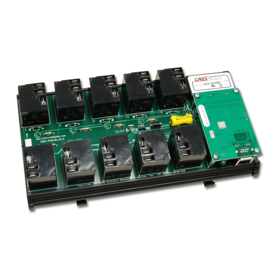
Revision 1.01 WebRelay-10 Users Manual 1.3 Connectors & Indicators WebRelay-10 has ¼ inch male tab connectors for power and relay contacts, an Ethernet connector, and thirteen LED indicators. Two tab connectors located on the circuit board are used to apply power to the module. Each relay has three tab connectors for direct connection to the relay contacts. -
Page 7: Section 2: Installation And Setup
Revision 1.01 WebRelay-10 Users Manual Section 2: Installation and Setup Installation consists of mounting WebRelay-10 , connecting to an IP network, providing power, configuring via a web browser, and wiring relay contacts to the device that will be controlled. 2.1 Mounting WebRelay-10 can be be mounted to a standard (35mm by 7.55mm) DIN rail. -
Page 8: Relay Connection
Revision 1.01 WebRelay-10 Users Manual 2.2.3 Relay Connection Direct connection to relay contacts is provided through tab connectors located on the top of the relays. Do not exceed specified load ratings for relay contacts (see specifications for load ratings). 2.3 Establishing Communications for Setup WebRelay-10 is set up using a web browser. -
Page 9: Option 2: Assign A Temporary Ip Address To Configuration Computer
Revision 1.01 WebRelay-10 Users Manual Serial number format is: ss:ss:ss:ss:ss:ss For example, to set a WebRelay-10 device (with serial number 00-0C-C8-01-00-01 ) to 10.10.10.40 the following command would be used. arp -s 10.10.10.40 00:0c:c8:01:00:01 Next, type... ping -s 102 {new IP address} For example, if the new IP address is 10.10.10.40, the following command would be used. - Page 10 Revision 1.01 WebRelay-10 Users Manual Step 2: Double click on the icon labeled Network Connections. The following menu will pop up. Step 3: Right click on the icon labeled Local Area Connection. Another menu will appear. Select the option at the bottom of the menu labeled Properties. The Local Area Connection Properties window will appear. Step 4: On the Local Area Connection Properties page scroll down to Internet Protocol (TCP/IP), select it, and then click the button labeled properties.
- Page 11 Revision 1.01 WebRelay-10 Users Manual Step 5: Before making any changes to the network settings, write down the current settings so they can be restored once WebRelay-10 is configured. Next, select the radio button labeled “Use the following IP address,” and type in the IP address 192.168.1.50. Type in a subnet mask of 255.255.255.0. Leave the default gateway field blank.
-
Page 12: Open Configuration Web Page
Revision 1.01 WebRelay-10 Users Manual 2.3.3 Open Configuration Web Page Once the network is set up, open the configuration setup page by typing the following URL into the browser: http://192.168.1.2/setup.html (note that if option 1 above was used for initial configuration, replace the IP address given here with the newly assigned IP address). -
Page 13: Network Setup Page
Revision 1.01 WebRelay-10 Users Manual Navigating between setup pages is done by clicking on the tabs at the top of the page. All setup pages require a password. The default password is ‘webrelay’ (no quotes, all lower case) and no user name is required. - Page 14 Revision 1.01 WebRelay-10 Users Manual (arp -d -a as super user on Apple OSX). Also note that the unit must be power-cycled (power disconnected, then reconnected) before network settings take effect. No other setup page requires power- cycling for the settings take effect. 1.
- Page 15 Revision 1.01 WebRelay-10 Users Manual convenience but details of setting up a configuration such as this is beyond the scope of this manual. If WebRelay-10 is used on a private network only and is NOT used over the Internet, a routable IP address is not necessary.
- Page 16 Revision 1.01 WebRelay-10 Users Manual An example screenshot of a gateway router configuration is given below. This setup allows seven ControlByWeb products to be accessed on a private network behind a gateway router. Note that this screenshot is simply an example of a typical router setup page.
-
Page 17: Password Setup Page
Revision 1.01 WebRelay-10 Users Manual 8. Mode: This option allows the Ethernet port to be set to Half Duplex or Full Duplex. Legacy Ethernet operates in Half Duplex mode which means that devices can either send data or receive data, but not both at the same time. Full duplex means that devices can send and receive data at the same time. -
Page 18: Relay Options Page
Revision 1.01 WebRelay-10 Users Manual 1. Main Header Text: This text will be displayed in the main header area of the control page. This field can be up to 25 characters in length. 2. Auto Refresh Page: Web pages traditionally display static information. The WebRelay-10 control page, however, displays information that is dynamic. - Page 19 Revision 1.01 WebRelay-10 Users Manual 1. Select Relay to Edit: This drop down box selects the relay for which the rest of the parameters on this setup page will apply. When a new relay is selected the setup page will be refreshed to reflect the current settings for that relay. 2.
- Page 20 Revision 1.01 WebRelay-10 Users Manual This field specifies the text that will be displayed when the relay is off (coil not energized). 5. Button 1 Label: This field specifies the text that will be displayed in pushbutton number 1. 6. Button 2 Label: This field specifies the text that will be displayed in pushbutton number 2.
-
Page 21: Section 3: Operation
Revision 1.01 WebRelay-10 Users Manual Section 3: Operation WebRelay-10 can be operated by using a web browser, by sending text commands to an XML status/control page, or by sending Modbus/TCP requests. 3.1 Browser Operation Once the unit is set up, the control page may be accessed by typing the following URL into the web browser: http://192.168.1.2 (Note that if the IP address was changed, replace the default IP address shown with the new address that was assigned. - Page 22 Revision 1.01 WebRelay-10 Users Manual Request the current state: http://192.168.1.2/state.xml This will return the following XML page.: <?xml version="1.0" encoding="utf-8" ?> - <datavalues> <relay1state>0</relay1state> <relay2state>1</relay2state> <relay3state>1</relay3state> <relay4state>1</relay4state> <relay5state>0</relay5state> <relay6state>0</relay6state> <relay7state>0</relay7state> <relay8state>0</relay8state> <relay9state>0</relay9state> <relay10state>0</relay10state> </datavalues> The tags <relay1state>... <relay10state> indicate the current state of each of the ten relays. Values for the tags are described below.
-
Page 23: Modbus Operation
Revision 1.01 WebRelay-10 Users Manual state.xml?relay1State=2&pulseTime1=5 This will pulse the relay for 5 seconds state.xml?relay1State=2&pulseTime1=5 This will pulse the relay for 5 seconds state.xml?relay1State=2 This will pulse the relay for the preset time (1.5 seconds) (Note that http://192.168.1.2/ would be included on all commands above) Multiple relays can be changed with a single command by submitting multiple relayXState variables separated by an ampersand symbol (&). -
Page 24: Read Coils (Modbus Function Code 01 (0X01))
Revision 1.01 WebRelay-10 Users Manual following commands are available: Read Coils (Modbus function 01) - read the status of the relay (and/or the input). Write Single Coil (Modbus function 05) - change the relay state Write Multiple Coils (Modbus Function Code 15) – change multiple relays at the same time Write Multiple Registers (Modbus function 16) - pulse the relay or multiple relays. -
Page 25: Write Single Coil (Modbus Function Code 05 (0X05))
Revision 1.01 WebRelay-10 Users Manual char read_coils_mb_response[] = {0x00, 0x01, 0x00, 0x00, 0x00, 0x04, 0xff, 0x01, 0x01, 0x01}; 3.3.2 Write Single Coil (Modbus Function Code 05 (0x05)) Request Modbus/TCP: Transaction identifier (2 Bytes): 0x0001 Protocol identifier (2 Bytes): 0x0000 Length (2 Bytes): 0x0006 Unit identifier (1 Byte): 0xff Modbus: Function code (1 Byte): 0x05 (write coil) -
Page 26: Write Multiple Registers (Modbus Function Code 16 (0X10))
Revision 1.01 WebRelay-10 Users Manual Modbus: Function code (1 Byte): 0x0f (write coil) Starting address (2 Bytes): 0x0000 ~ 0x0009 Quantity of outputs (2 Bytes): 0x0001 ~ 0x000A Byte count (1 Byte): 0x01 Output value (1 to 2 Bytes): 0x0000 ~ 0x3ff char write_mult_coil_mb_request[] = {0x00, 0x01, 0x00, 0x00, 0x00, 0x08, 0xff, 0x0f, 0x00, 0x00, 0x00, 0x01, 0x01, 0x0F };... - Page 27 Revision 1.01 WebRelay-10 Users Manual Length (2 bytes): 0x000b Unit identifier (1 byte): 0xff Modbus: Function code (1 Byte): 0x10 (Write Multiple Registers) Starting address (2 Bytes): 0x0010 (0x0010 relay1, 0x0012 relay 2, 0x0014 relay 3, 0x0016 relay 4, .., 0x0023 relay 10) Number of registers (2 Bytes): 0x0002-0x0014 (2 registers for each relay to be pulsed) Byte count (1 Byte): 0x04 - 0x28 (2 times the number of registers) Register values (4 Bytes for each relay to be pulsed): 00 00 41 20 (10 second pulse time)
-
Page 28: Appendix A: Restoring Factory Default Settings
Revision 1.01 WebRelay-10 Users Manual Appendix A: Restoring Factory Default Settings In the event that the IP address or passwords are forgotten, WebRelay-10 may be restored to its original factory default settings. To do this, first remove the power from the unit. Next, press the small button that is located on the front of the CPU daughter-board. - Page 29 Revision 1.01 WebRelay-10 Users Manual Mechanical Life: 10M cycles, typ Connectors: ¼ inch Tab Connectors Network: 10/100Base-T Ethernet Network Setup: static IP address assignment, TCP port selectable Relay Control Options: ON/OFF or Pulsed Pulse Timer Duration: 100ms to 86400 Seconds (1 day) LED Indicators: 13 -Module Powered -Relay Coils Energized 1-10...
-
Page 30: Appendix C: Open Tcp Legal Notice
Revision 1.01 WebRelay-10 Users Manual Appendix C: Open TCP Legal Notice Portions of the software used in WebRelay-10 are open source. The appropriate notices are listed below. All other parts of the software are property of Xytronix Research & Design, Inc. ©2005-2006. Copyright (c) 2000-2002 Viola Systems Ltd.
Need help?
Do you have a question about the ControlByWeb WebRelay-10 and is the answer not in the manual?
Questions and answers