Table of Contents
Advertisement
Quick Links
Advertisement
Table of Contents

Related Manuals for Wi-Tek WI-PCES306G


Summary of Contents for Wi-Tek WI-PCES306G
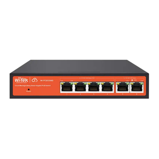
- Page 2 This manual applies to the following switch models Interface model WI-PCES306G 4-port PoE+ and 2-port RJ45 WI-PCES310GF 8-port PoE+ and 2-port SFP Copyright notice Disclaimers Preface Reader object This document is suitable for the following people Network Engineer Technical Promotion Personnel ...
-
Page 3: Table Of Contents
1 Overview ..............4 2 Configuration Guide ............4 2.1 Power ..............4 2.2 Connecting to the Network ..........5 2.3 Starting the Web-based Configuration Utility ........ 5 2.5 Logging In ............6 2.6Web-based Switch Configuration ...........7 3 Web Smart Configuration ............. 9 3.1 Homepage ............. -
Page 4: Overview
Web Smart Function Configuration 1 Overview Web Smart refers to the device web management system, that is, the web management system that manages or configures the device, and manages the device by accessing Web Smart using a browser (such as Chrome). Web management includes two parts: Web server and Web client. -
Page 5: Connecting To The Network
source with the included power cord, and check the power LED is on. 2.2 Connecting to the Network To connect the switch to the network: Connect an Ethernet cable to the Ethernet port of a computer Connect the other end of the Ethernet cable to one of the numbered Ethernet ports of the switch. -
Page 6: Logging In
2.5 Logging In The default username is admin and the default password is admin. To log in to the device configuration utility: Enter the default user ID (admin) and the default password (admin). If this is the first time that you logged on with the default user ID (admin) and the default password (admin) it is recommended that you change your password immediately. -
Page 7: Web-Based Switch Configuration
the Login page appears, with a message indicating the logged-out state. After you log in, the application returns to the initial page. 2.6Web-based Switch Configuration The Websmart switch software provides Layer 2 functionality for switches in your networks. This chapter describes how to use the web-based management interface (Web UI) to configure the switch’s features. - Page 8 When a loop appears on the port, the port icon displays yellow When the port works normally, the port icon displays green The content area sometimes presents orange text (indicating the description of the function block) And a question mark with an orange background (indicating the prompt description of the operation, and the mouse moves up to display the description text).
-
Page 9: Web Smart Configuration
3 Web Smart Configuration 3.1 Homepage The homepage interface displays the basic information of the device. 3.2 System Settings 3.2.1 Device Info Configure the information of the device, including Device Name, Device Contact and Device Location. 3.2.2 IP Settings Configure device management IP (default static IP: 192.168.0.1) -
Page 10: Web Settings
Tips: 1. When configuring IP, the device will be disconnected briefly. If automatic IP acquisition is enabled, you need to obtain the configuration IP from the uplink device or web management through device management IP: 10.XX.XX.XX(XX.XX.XX is the last three digits of the MAC address of the current device). -
Page 11: User Management
3.2.5 User Management Configure the password for web page login (The password must contain 6-16 characters and contain only letters, numbers and the following special characters: <=>[]!@#$*().) 3.2.6 Upgrade System upgrade can be divided into Local upgrade and Online upgrade: 1. -
Page 12: Monitoring
3.3 Monitoring 3.3.1 Port Statistics The Port Statistics page displays the data statistics and status of the device port, such as the port sending and receiving rate, sending and receiving packets, etc. 3.3.2 Cable Diagnostics You can roughly understand the cable condition of the corresponding port through cable detection (such as whether the cable is short circuited, disconnected, etc.). -
Page 13: Loop Guard
3.3.3 Loop Guard Configure enable loop guard. Tips: The port causing the loop will be shut down. After the loop is removed, the port will be up automatically.(Default is enable)。 3.4 Switch Settings 3.4.1 Port Settings Port configuration can batch configure the status, speed, duplex, flow control and EEE properties of ports. -
Page 14: Port Mirroring
Display part: Displays the configuration attributes and actual effective attributes of each port of the device. 3.4.2 Port Mirroring The input / output messages of one or more source image ports are forwarded to the destination image port to monitor the network. Tips: 1. -
Page 15: Port Isolation
3.4.3 Port Isolation Configure isolation port group 3.4.4 Static MAC The static MAC configuration is divided into two parts. Static MAC add: Enter the legitimate MAC address, VLAN ID, and select the configured port number. Click 《Add》 to add static MAC. Static MAC deletion and display: After adding a legal static Mac, the corresponding data will be displayed;... -
Page 16: Filter Mac
3.4.5 Filter MAC Configure filtered MAC address Tips: 1. Filter MAC addresses maximum can be configured 16. 3.4.6 Search MAC Search the MAC table learned by the device (support fuzzy search) Tips: 1. The inquiry waiting process will interrupt the communication with the equipment 3.4.7 MAC List Displays the list of MAC learned by the device... -
Page 17: Dhcp Snooping
Click《Clear Dynamic MAC》and the device will get the learning MAC list again. Tips: 1. The display waiting process will interrupt communication with the device 3.4.8 DHCP Snooping Configure DHCP Snooping function, which is disabled by default. When DHCP Snooping is enabled, you can choose to trust ports or not. As shown in the following figure, the device sets the selected ports as trusted ports, and if it is not selected, all ports are untrusted ports;... -
Page 18: Vlan Settings
only forward the response message from the trust port. 2. Generally, the DHCP server port (upper connection port) is set as the trust port. 3.5 VLAN Settings Add or delete device VLAN members and port VLAN configuration 3.5.1 VLAN Member Configuration part: Enter a valid VLAN ID and click 《Save》to configure a new VLAN member;... -
Page 19: Qos Settings
configure and save port VLAN (Permit VLAN and Native VLAN are selected from the VLAN members configured above); Part II: Port VLAN list, which displays the VLAN configuration of the device port. Tips: the message under Native VLAN does not have VLAN tag. 3.6 QoS Settings Including port rate limit and storm control functions. -
Page 20: Storm Control
Display part: displays the ingress rate and egress rate of the device port configuration. Tips: 1. Rate limit range: 1-1000M 3.6.2 Storm Control Including port storm control configuration and display: Configuration part: Select the configured storm control type, one or more ports and whether to enable storm control (when enabled, enter the rate of storm control configuration), and click《Save》... -
Page 21: Poe Settings
Tips: 1. Rate limit range: 1-1000M 3.7 PoE Settings Tips: Some models support Poe function 3.7.1 PoE Global Info Displays the global information of the device Poe function... -
Page 22: Poe Basic Settings
3.7.2 PoE Basic settings Includes port PoE configuration and display: Configuration part: Select the PoE power supply status, priority and limited power of the configured port, and click 《Save》 to configure PoE. Display part: Display the power of port PoE and the current power supply status; Tips: 1. -
Page 23: Cloud Settings
Click《Detect》to discover devices. 3.9 Cloud Settings The cloud settings function is implemented based on the MQTT protocol, and the device is used as an MQTT client. Select “Enabled” for “MQTT Client”, configure the IP address and port of the cloud for MQTT Server IP address and port, and click《Save》to configure;... -
Page 24: Frequently Asked Questions
4 Frequently Asked Questions Question 1: unable to log in to the device manager web management interface. What should I do? Refer to the following steps: 1) Confirm that the PC network cable is normally connected to the device port, and the corresponding indicator flashes.
Need help?
Do you have a question about the WI-PCES306G and is the answer not in the manual?
Questions and answers