Table of Contents
Advertisement
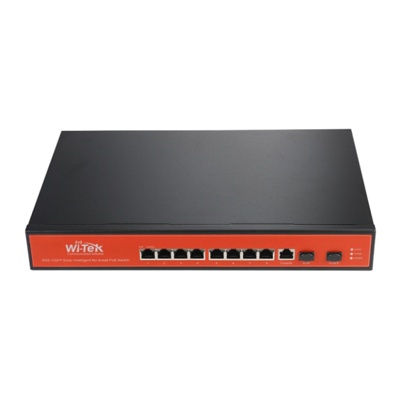
Wi-Tek Solar UPS no-break Managed PoE
一、Overview of the Switch .......................................................................................................... 2
、
1
、
2
、
3
、
4
、
5
、
6
、
7
、
............................................................. 9
8
、
............................................................ 10
9
二、WEB PAGE INTRODUCTION ............................................................................................ 11
、
1
、
........................................................... 11
2
、
3
、
4
、
........................................................... 27
5
、
............................................................ 29
6
、
7
、
8
、
9
、
10
、
11
、
12
、
13
、
14
、
15
、
16
、
17
、
18
、
19
、
20
、
21
Switch Manual
Contents
............................................ 5
............................................ 6
............................................ 7
................................................ 8
................................................ 8
........................................................ 9
...................................................... 11
................................................. 12
..................................................... 20
................................................... 30
................................................... 33
..................................................... 35
.................................................... 37
................................................. 43
................................................... 46
.................................................. 51
........................................ 53
................................................. 54
.................................................. 56
................................................. 57
................................................. 60
................................................. 62
.................................................... 63
............................................... 64
................................... 5
www.wireless-tek.com
1 / 65
Advertisement
Table of Contents

Related Manuals for Wi-Tek WI-PMS310GF-UPS


Summary of Contents for Wi-Tek WI-PMS310GF-UPS
-
Page 1: Table Of Contents
Wi-Tek Solar UPS no-break Managed PoE Switch Manual Contents 一、Overview of the Switch ......................2 、 ..........5 WEB access' characteristics 、 ........5 WEB browsing' s system requirements 、 ..........6 WEB browsing session login 、 ..........7 WEB page basic composition 、... -
Page 2: 一、Overview Of The Switch
2 gigabit SFP slots, expanding your network flexibly. WI-PMS310GF-UPS UPS system is designed specifically for 24VDC POE equipment like that from Ubiquiti, WI-TEK, Mikrotik, etc. The system provides up to 150W of continuous total PoE power on 8 switched PoE ports. Its inside battery controller maintains the proper charge on the batteries to prevent over charge and controls the load to prevent over discharge. - Page 3 support solar panel and battery for 24-hours back-up time Inside solar controller and battery controller for charge and dis-charge battery circulatory from solar Panel and AC Restart AP via PoE managed page remotely Up to 4K QVLANs simultaneously ...
-
Page 4: Hardware Features
HARDWARE FEATURES 8 10/100/1000Mbps RJ45 Ports (Auto Negotiation/Auto Interface MDI/MDIX) 2 1000Mbps SFP Slots 1 Console Port 10BASE-T: UTP category 3, 4, 5 cable (maximum 100m) 100BASE-TX/1000Base-T: UTP category 5, 5e, 6 or above Network cable (maximum 100m) Media 1000BASE-X: MMF, SMF 1000Base-L X:62.5μm/50μm MM(2m~550m) or 10μm SMF(2m~5000m) -
Page 5: Web Access' Characteristics
HARDWARE FEATURES Capacity Packet Forwarding 14.9Mpps Rate Mac Address Table Packet Buffer Memory Jumbo 10240 Bytes Frame Product Size: Dimensions 225mm* 105mm*32mm (L*W*H) 1、WEB access' characteristics The switch provides the features of Web access for users.Users can access the switch through the Web browser and manage and configure the switch.The main characteristics of WEB access : ... -
Page 6: Web Browsing Session Login
Hardware System Requirement Software Pentium 586 above 128MB above Resolution 800x600 above Color 256 colors above Browser IE4.0 above or Netscape4.01 above Operating Microsoft ,Windows95 ,Windows98 ,WindowsNT ® ® ® ® System Windows2000 ,WindowsXP ,WindowsME , WindowsVista ® ® ® ®... -
Page 7: Web Page Basic Composition
Pic 1 WEB login page for browsing session 4、WEB page basic composition Figure 2,The WEB page consists of three parts: the title page, the navigation tree page, and the main page. Pic 2 Switch Web page basic composition page 7 / 65 www.wireless-tek.com... -
Page 8: Navigation Tree Structure
Title Page Used to display the logo, and real-time port status as shown below The green light indicates that the port is connected; The gray light indicates that the port is not connected; The red light indicates that the port is off ( the specific setting is shown in Figure 17 ) Main page Used to display the page selected by the user from the navigation tree. -
Page 9: Error Message
done by the Web server, there is no error check before the user selects the button Delete Delete the current record Help Open the help page and view the configuration instructions for each page 7、Error message If the switch's WEB server is in error when processing user requests, the corresponding error message is displayed in a dialog box.For example, Figure 4 shows an error message dialog box. -
Page 10: State Field
Pic 5 Entry field's page 9、State field There are some pages in the rightmost column of the table that have a status field, as shown in Figure 6, where the field shows the row state.Since all row state changes are processed internally, the status field is read-only.Once all the domain information in the row is valid, the row state becomes automatically active. -
Page 11: 二、Web Page Introduction
二、WEB PAGE INTRODUCTION The WEB pages of the switch are organized into groups, each consisting of one or more Web pages. The following is an introduction to each page. 1、Login dialog box Pic 7 WEB Browse the session's login page Figure 7 shows the login dialog box, which is displayed when the user first logs in to the web page.The user enters the user name and password in the corresponding field, and then clicks the OK key to log in to the Web server of the switch.Password is case-sensitive,... -
Page 12: System Configuration
Pic 8 Switch the main page 3、System Configuration Language switching: switch buttons in the upper right corner and easily switch between Chinese and English system interfaces. (1)Basic information page Figure 9 shows the basic information configuration page where the user can configure the basic information for the switch. - Page 13 The system location displays the physical location of the switch in the network, and the user can modify the system location. System contact display management of the current node contacts and contact information, the user can modify the system contact. Pic 9 Basic information page (2)Serial port configuration page Figure 10 shows the serial port configuration page, which shows the serial port baud rate...
- Page 14 Pic 10 Serial port configuration page (3)Multi-user management configuration page Figure 11 shows the Multi-user management configuration page, through this page users can modify the switch's anonymous user (admin) password.Telnet and Web use the same anonymous user password when multiple users are not enabled.Passwords are case sensitive and you can set up to 16 characters at most.If you want to change the password, the user needs to enter the new password twice, once the user clicks the application key, the new password is activated,If the switch does not enable multi-user, will display the login dialog box...
- Page 15 Pic 11 Multi-user management configuration page (4)User safety configuration page Figure 12 shows the user safety configuration page, through the configuration of the page, the administrator can control the network management services TELNET, WEB and SNMP control, you can open or close these services,These services can be linked with the IP standard ACL group, the implementation of source IP address control, control the host access to these services.
- Page 16 Pic 12 User safety configuration page (5)SNTP configuration page Figure 13 shows the SNTP configuration page, where the administrator can configure and view the system clock through configuration of the page. Pic 13 SNTP configuration page (6)Current configuration file page 16 / 65 www.wireless-tek.com...
- Page 17 Figure 14 shows the current configuration file page.Through this page, the user can view the current configuration of the switch.The save key stores the current configuration of the system into the configuration file.Because the storage operation needs to erase the FLASH chip, which takes a certain amount of time.When the user is configured on the page and want the configuration is not lost after restart the switch , you must click the Save button before exit the page in the current configuration page.
- Page 18 Pic 15 Configuration file page (8)File upload page Figure 16 shows the file upload page, through which users can upload configuration files and image files to the switch.Click the Browse button to select the directory path of the uploaded profile or image file on the PC.Click the upload key to upload the configuration file or image file.
- Page 19 Pic 16 File upload page (9)System reset page Figure 17 shows the system reset page, through this page users to restart the switch.When you click the restart button, a dialog box will pop up prompting you if the user is sure to restart the switch.
-
Page 20: Port Configuration
Pic 17 System reset page 4、Port configuration (1)Port configuration/show page Figure 18 shows the port configuration/show page.The user can enable or disable the port through this page, set the port speed, or view the basic information of all ports. To set a specific port, select the appropriate port name in the drop-down menu for the user's port.Port status defaults to up, and you can select the down in the drop-down menu to disable the port.The user can also choose to set the speed drop-down menu to set the speed of the port, such as the mandatory semi-duplex for the port, 10M (half - 10), etc. - Page 21 Pic 18 Port configuration/show page (2)Port statistics information page Figure 19 shows the port statistics information page.To view a particular port, select the appropriate port name in the drop-down menu for the user's port.Users can view the statistics of the port send and receive packet through this page. Pic 19 Port statistics information page 21 / 65 www.wireless-tek.com...
- Page 22 (3)Flow control page Figure 20 shows the flow control page.The user can use this page to open or close the flow control for each port. Through the drop-down on or off of the flow control to open or close a port flow control.At the same time through this page you can view the flow control status of all ports.
- Page 23 Pic 21 Broadcast storm control page (5)Port rate limit page Figure 22 shows the port rate limit page。This page is used to configure the rate at which ports are sent and received. Select the port to be configured from the drop-down bar of the port.The transmit packet bandwidth control is used to configure and display the bandwidth control of the sending data packet, in the range of 1-1024000, in kbits, after enter, press the application key to take effect.
- Page 24 Pic 22 Port rate limit page (6)Protected port page Figure 23 shows the protected port page。This page is used to configure the protection port. Pic 23 Protected port page 24 / 65 www.wireless-tek.com...
- Page 25 (7)Port learn limit page Figure 24 shows the port learn limit page。This page is used to limit the number of MAC addresses that the port can learn. The range is 0-8191.The default value is 8191, which is also the maximum value, indicating that the port is not configured with learning restrictions.The list shows the learning limits for all ports.
- Page 26 Delete Trunk Group key. During the page configuration process, the aggregation method is configured to correspond to the selected trunk group ID. The existing Trunk group can configure the aggregation method. You can add or remove member ports on the existing Trunk. In the case of no member ports, To delete a Trunk group.
-
Page 27: Mac Bind
When the RECEIVE in the listening direction is selected, it indicates that the received packet is received, TRANSMIT indicates the packet to be sent, BOTH indicates all the packets that are being sent and received, NOT_RECEIVE indicates that the received packet is canceled, NOT_TRANSMIT indicates that the packet is canceled Of the packet, NEITHER that cancel the monitor received and sent the packet, that is, to cancel the listening port. - Page 28 Pic 27 MAC bind configuration page (2)MAC auto bind page Figure 28 shows the MAC binding auto-conversion page. This page is used to implement the port automatically bind MAC address. Displays the dynamic MAC address and the VLAN of the port in the two tier hardware forwarding table.You can select items from them and convert them into static bindings.
-
Page 29: Mac Filter
Pic 28 MAC auto bind page 6、MAC filter (1)MAC filter configuration page Figure 29 shows the MAC Filter Configuration page. This page is used to configure the port to filter the MAC address. The MAC address on the page is used to enter the filtered MAC address. The VLAN ID entry is used to enter the VLAN to which the MAC address belongs. -
Page 30: Vlan Configuration
Pic 30 MAC auto filter page 7、VLAN configuration (1)VLAN information page Figure 31 shows the current VLAN information page. The page is a read-only page that shows the current VLAN, VLAN status, and VLAN port members. Drop-down box will show all the current vlan, the list shows up to 30 vlan VID, state and port members.Select a vlan from the drop-down box, and the list will display information with a VID greater than 30 vlan for that vlan. - Page 31 Pic32 VLAN information page (2)Static VLAN conformation page Figure 32 shows a static VLAN configuration page, which allows users to create VLAN. If you want to create a new VLAN, the user enters a VID in the active line, ranging from 2 to 4094.
- Page 32 Pic 32 Static VLAN conformation page (3)VLAN port configuration page Figure 33 shows the VLAN port configuration page, which is used to configure VLAN on the port and display the results of the configuration. The page consists of eight parts: port, mode, all current VLAN, ports owned by VLAN, "default VLAN =>", "tagged =", "untagged =>"...
-
Page 33: Snmp Configuration
Press "untagged =>" to configure the port as an untagged member of the specified VLAN, and select one or more VLAN from all the current VLAN. The key "Non-member <=" removes the port from the specified one or more VLAN, is no longer a member of these VLAN, and selects one or more VLAN from the VLAN to which the port belongs. - Page 34 Pic 34 SNMP community configuration page (2)TRAP target configuration page Figure 35 shows the TRAP target configuration page, which allows the user to configure the IP address of the workstation that received the TRAP message and Some parameters of the TRAP protocol package. When configuring an entry, the name is used to enter the TRAP name.
-
Page 35: Qos Configuration
Pic 35 TRAP target configuration page 9、Qos configuration (1)Qos apply page Figure 36 shows the Qos application page, the user can use this page to configure the port QOS type, but also can modify the default user priority. The list is the real-time display port Qos type and user default priority. - Page 36 Pic 36 Qos apply page (2)Qos schedule page Figure 37 shows the Qos scheduling page, the user can use this page to configure the port QOS scheduling type, but also can modify the queue priority. The list is the real-time display port scheduling mode and the weight value of each queue.
-
Page 37: Acl Configuration
Pic 37 Qos schedule page 10、ACL configuration (1)ACL standard IP configuration page Figure 38 shows the ACL standard IP configuration page. You can use this page to create a rule base for ACL standard IP. The user can select an ACL group number (range between 1-99, or 1300-1999) to create one or more rules in the group. - Page 38 Pic 38 ACL standard IP configuration page When a user configures a rule, the source IP address needs to be masked. The rule can match the set of IP addresses. The address mask is represented by an anti-code. If the rule matches the IP address range 192.168.0.0 to 192.168.0.255, the IP address can be 192.168.0.1 and its mask is 0.0.0.255.
- Page 39 Pic 39 ACL extended IP configuration page When a user configures a rule, the source IP address and destination IP address must be masked. The rule can match the set of IP addresses. The address mask is represented by an anti-code.
- Page 40 Pic 40 ACL MAC IP configuration page When a user configures a rule, the source MAC address, source IP address, and destination IP address need to match the address. The rule can match the MAC address and the IP address. For example, if the rule matches the IP address range 192.168.0.0 to 192.168.0.
- Page 41 Pic 41 ACL MAC ARP configuration page When a user configures a rule, the MAC address and the IP address are sent with an address matching bit. The rule can match the set of MAC address and IP address. For example, if the rule matches the IP address range 192.168.0.0 to 192.168.0.
- Page 42 Pic 42 ACL resource information page (6)ACL reference configuration page Figure 43 shows the ACL reference configuration page. You can use this page to select an ACL group for a port and write the rules in this ACL group to the port hardware logic to enable the port to perform ACL filtering on the received packets according to these rules.
-
Page 43: Ip Basic Configuration
Pic 43 ACL reference configuration page 11、IP basic configuration (1)VLAN interface configuration page Figure 44 shows the VLAN interface configuration page. You can configure the VLAN interface, remove the VLAN interface, configure the IP address of the interface, delete the IP address of the interface, and view the interface information. - Page 44 Pic 44 VLAN interface configuration page The switch has a VLAN1 interface by default, and the interface can not be deleted. Only one interface can be configured for one VLAN. (2)ARP configuration and display page Figure 45 shows the ARP configuration and display page. This page displays all the information of the ARP table of the switch.
- Page 45 Pic 45 ARP configuration and display page (3)Host static route configuration page Figure 46 shows the host static routing configuration page, the user can add and delete the host static route of the switch. By default, no static route is configured on the switch. You can use this page to configure a default route, that is, the destination / subnet prefix is 0.0.0.0/0.
-
Page 46: Aaa Configuration
Pic 46 host static route configuration page 12、AAA configuration (1)Tacacs+configuration page Figure 47 shows the Tacacs + configuration page. The user can configure information related to Tacacs +. The following information can be set: Enable Tacacs + function, configure the Tacacs + server IP address, authentication type, and shared secret key. Before using the Tacacs + function, you must enable the Tacacs + function, which is configured by default. - Page 47 Pic 47 Tacacs+configuration page. (2)Radius configuration page Figure 48 shows the Radius configuration page, the user can configure information related to Radius, can set the information include: Radius server IP address, in the authentication and billing must be set when this field.
- Page 48 Pic 48 Radius configuration page (3)802.1x configuration page Figure 49 shows the 802.1x configuration page. You can configure 802.1x-related information through this page, including: Whether to start the 802.1x protocol, be sure to start the 802.1x protocol when doing authentication and accounting. ...
- Page 49 Check Client, whether to check the client's timing traffic package after authentication has passed. Pic 49 802.1x configuration page (4)802.1x port configuration page Figure 50 shows the 802.1x port configuration page. You can configure 802.1x port mode and the maximum number of hosts that can be configured. You can also view the 802.1x configuration of each port.The 802.1x port mode includes four types: N / A status, Auto state, Force-authorized status, and Force-unauthorized status.当When A port needs to be done to 802.1 x authentication, to the state of the port is set to Auto, if don't do certification can access...
- Page 50 Pic 50 802.1x port configuration page. When 802.1x authentication is enabled, the maximum number of hosts that can be accessed by the port is 256, and the user can modify this field to support up to 256. (5)802.1x user auth-information page Figure 51 shows the 802.1x user auth-information page.
-
Page 51: Mstp Configuration
13、MSTP configuration (1)MSTP global configuration page Figure 52 shows the MSTP global configuration page. You can configure global MSTP parameters through this page. Pic 52 MSTP global configuration page (2)MSTP port configuration page Figure 53 shows the MSTP port configuration page. You can use this page to configure port MSTP parameters. - Page 52 Pic 53 MSTP port configuration page (3)MSTP port information page Figure 54 shows the MSTP port information page. You can view the port MSTP status on this page. Pic 54 MSTP port information page 52 / 65 www.wireless-tek.com...
-
Page 53: Igmpsnooping Configuration
14、IGMPSNOOPING configuration (1)IGMPsnooping global configuration page Figure 55 shows the IGMPsnooping global configuration page. You can enable IGMP snooping on this page. Pic 55 IGMPsnooping global configuration page (2) Multicast group information page Figure 56 shows the multicast group information page. You can view the igmp snooping multicast program information from this page. -
Page 54: Gmrp Configuration
15、GMRP configuration (1)GMRP global configuration page Figure 57 shows the GMRP global configuration page. Users can enable GMRP through this page. Pic 57 GMRP global configuration page (2)GMRP port configuration page Figure 58 shows the GMRP port configuration page.Users can use this page to enable port GMRP, and can view the port information. - Page 55 Pic 58 GMRP port configuration page (3)GMRP state machine page Figure 59 is the GMRP state machine page.Users can view GMRP's state machine information from this page. Pic 59 GMRP state machine page 55 / 65 www.wireless-tek.com...
-
Page 56: Eaps Configuration
16、EAPS configuration (1)EAPS configuration page This page is used to create and configure EAPS information, and can also be used to delete and display EAPS information. EAPS Ring ID The specific ring ID, in the range of 1-16, can be selected according to the drop-down box Create two types, Not Created and Created ,If you don't create it, you have to create the pattern Master and the Transit, The corresponding mode can be configured according to the... -
Page 57: Rmon Configuration
information from this page. Pic 61 EAPS information page 17、RMON configuration (1)RMON statistics group configuration page Figure 62 shows the RMON statistics group configuration page.The user can configure the RMON statistics group through this page.Select a port from the drop-down list to view / configure the RMON statistics group configuration for that port.If the index number is 0, the correct index number (in the range of 1 to 100) is filled and the owner is optional. - Page 58 Pic 62 RMON statistics group configuration page (2)RMON history group configuration page Figure 63 shows the RMON history group configuration page.User can configure the RMON history group from this page.Select a port from the drop-down list to view / configure the RMON history group configuration for that port.If the index number is 0, the correct index number (in the range of 1 to 100), the interval, the request Buckets, and the owner is optional.
- Page 59 Figure 64 shows the RMON alarm group configuration page, where users can create or modify the RMON alarm group.Select a configured alarm group from the drop-down list to view / configure its information and select New to create it.The index range is 1 to 60, the interval is 1 to 3600, in seconds, the monitoring object must fill in the MIB node, the contrast can choose absolute or delta,Also must fill in the upper and lower threshold, the event index, the owner is optional.The alarm value is read-only and shows the sampled value when the last alarm was...
-
Page 60: Cluster Configuration
Pic 65 RMON event group configuration page 18、Cluster configuration (1)NDP configuration page Figure 66 shows the NDP configuration page, where users can configure NDP.The information that can be set includes: port selection, port NDP function, global NDP function, NDP packet sending interval, and aging time of NDP packets on the receiving device. Port selection, select the port as required, and enable the port NDP function. - Page 61 Configure the range of topology collection. The effective range is 1-6. In the default topology, the maximum hop count of the device is 3. Configure the interval for collecting topology information. The effective range is 0-65535 minutes. The default configuration is 1 minute. Configure the delay time for forwarding packets on the first port.
-
Page 62: Erpsc Configuration
Configure the effective retention time of the device. The effective range is 1-255 seconds. The default configuration is 60 seconds. To establish a cluster, you need to configure the cluster name, choose to join the cluster, the way to join both manual and automatic. After the cluster is set up, it can be automatically switched to manual, but manual can not be switched to automatic.Manual mode can change the cluster name. -
Page 63: Log Management
Protocol VLAN configuration,delete ERPS ring protocol VLAN (<2-4094>) Data VLAN Configuration ERPS Ring Data VLAN (<1-4094>) Ring port Configuration, delete ERPS ring port, RPL port or common ring port Restore Behavior Configure ERPS ring recovery behavior, recoverable or unrecoverable hold-off Time Configure the ERPS loop hold-off time (<0-10000>), in ms, the default is 0 Guard Time Configure the ERPS ring guard time (<10-2000>), in ms, defaults to 500 Wtr Time... -
Page 64: Poe Port Configuration
Pic 71 Log information page 21、POE port configuration (1)POE port configuration Figure 72 shows the 48V 802.3af/at POE product configuration page. You can configure POE device total power (to be updated), POE single port power (to be updated), POE on or off;This page allows you to view information about the current POE device POE port:Select the power supply port number (1-24) POE commodity status:enable or disable... - Page 65 Figure 73 shows the POE schedule configuration page. Through scheduling management, you can enable or disable POE power supply according to actual requirements. The control mode is hour + week mode. Control port:Used to select the ports that need scheduled management (1-24) control function:enable or disable Pic 73 48V 802.3af/at POE schedule configuration page (3)POE Online detection (system to be updated)
Need help?
Do you have a question about the WI-PMS310GF-UPS and is the answer not in the manual?
Questions and answers