
Related Manuals for Jetson Bolt


Summary of Contents for Jetson Bolt
- Page 1 Bolt Electric Ride-On. A guide for your ride. IMPORTANT: READ CAREFULLY AND RETAIN FOR FUTURE REFERENCE. MODEL: JBOLT-BLK | JBOLT-LLC | JBOLT-SCR | JBOLT-BLK-RA | JBOLT-BLK-RB Designed in Brooklyn...
- Page 3 Jetson's top two riding rules: Be safe. Have fun!
-
Page 6: Table Of Contents
Contents Safety Warnings ................................6 Warranty Coverage ..............................9 Product Overview ..............................10 Specs & Features ..............................14 Rider Suitability ...............................14 Online Resources ..............................15 1. Getting Started Unfolding & Folding ..............................17 Attaching the Seat ..............................21 Attaching the Rear Fender ............................23 Attaching the Footrests ............................26 Securing the Bell ..............................28 2. - Page 7 Using the Lights ..............................38 Using the Bell ................................39 Using the Kickstand .............................40 Using the Carrying Handle ..........................41 4. Making Moves Riding the Bolt ..............................42 Using Cruise Control ............................43 Using the Brakes ..............................44 Maximizing Speed & Riding Range ........................44 5. Safe Journeying Pre-Ride Safety Checks ............................45...
-
Page 8: Safety Warnings
Safety Warnings • Before use, please read the user manual and safety warnings carefully, and make sure you understand and accept all the safety instructions. The user will be responsible for any loss or damage caused by improper use. • Please check the drive system and frame before riding to ensure safety. •... - Page 9 • Applying brakes too hard or too suddenly can lock up a wheel, which could cause you to lose control and fall. Sudden or excessive application of the brake may result in injury or death. • If the brake loosens, please adjust with a hexagon wrench, or please contact the Jetson Care Team. • Replace worn or broken parts immediately.
- Page 10 For all maintenance repairs and needs beyond the capability of the consumer, which may include but not be limited to: such as proper maintenance of brakes, control cables, bearing adjustments, wheel adjustments, lubrication, reflectors, tires and handlebar and seat adjustments, please contact the Jetson Care Team for assistance at: ridejetson.com/chat ridejetson.com/support...
-
Page 11: Warranty Coverage
ONE-YEAR GENERAL LIMITED WARRANTY All new Jetson products are warranted against defects in materials and workmanship for a period of one year from the date of original retail purchase when used in accordance with Jetson's user manuals (refer to ridejetson.com/support). -
Page 12: Product Overview
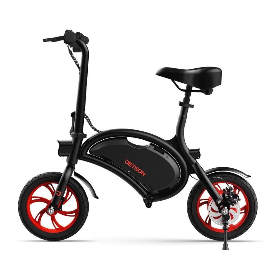
Product Overview WHEEL (X2; FRONT AND REAR) CARRYING HANDLE a. TIRE CHARGING PORT WITH COVER b. TIRE VALVE WITH DUST CAP SEAT* c. RIM SEAT CLAMP d. AXLE NUT REAR / BRAKE LIGHT e. SPOKES DISC BRAKE HEADLIGHT KICKSTAND FOLDING LATCH WITH LOCKING RING FOOTREST (X2)* HANDLEBAR FENDER (X2;... - Page 13 NOTE: IMAGES MAY NOT REFLECT EXACT APPEARANCE OF ACTUAL PRODUCT.
- Page 14 BELL HEADLIGHT SWITCH BATTERY CHARGE DISPLAY SCREEN TWIST THROTTLE CRUISE CONTROL BUTTON HANDLEBAR CLAMP POWER BUTTON HANDBRAKE...
- Page 15 INCLUDED TOOLS FOR ASSEMBLY, TIGHTENING, AND MAINTENANCE: (DEPENDENT ON THE PRODUCTION DATE OF YOUR BOLT, YOU RECEIVED ONE OF THE FOLLOWING TOOL COMBINATIONS.) 2-BIT TOOL WITH PHILLIPS-HEAD SCREWDRIVER AND 5MM ALLEN KEY TIPS 10 MM SPANNER WRENCH 2-BIT TOOL WITH PHILLIPS-HEAD SCREWDRIVER AND...
-
Page 16: Specs & Features
Specs & Features · PRODUCT DIMENSIONS, UNFOLDED: 40.75” (L) × 14.5” (W) × 21” (H) · BRAKE TYPE: REAR DISC · PRODUCT DIMENSIONS, FOLDED: 40.75” (L) × 19” (W) × 37.5” (H) · WEIGHT LIMIT: 265 LBS · PRODUCT WEIGHT: 34 LBS ·... -
Page 17: Online Resources
Online Resources Scan for our most updated Bolt onboarding materials and support resources. WARNING FAILURE TO COMPLY WITH THE FOLLOWING INSTRUCTIONS MAY RESULT IN INJURY TO THE CHILD OR OTHERS. • KEEP SMALL PARTS AWAY FROM CHILDREN DURING ASSEMBLY. • ACCESSORY MUST BE ASSEMBLED AND REMOVED BY AN ADULT. -
Page 18: Getting Started
THE DIRECTIONS GIVEN IN THIS MANUAL—RIGHT, LEFT, FRONT/FORWARD, AND REAR/BACK—ARE ORIENTED AS THE RIDER WOULD SEE THEM WHEN SEATED ON THE BOLT. THE “RIGHT SIDE” OF THE BOLT, FOR EXAMPLE, IS THE SIDE WHERE THE RIDER’S RIGHT HAND AND FOOT WILL BE. -
Page 19: Unfolding & Folding
Unfolding & Folding the Handlebar WHEN TO UNFOLD: FOR RIDING WHEN TO FOLD: FOR STORAGE AND TRANSPORT HOW TO UNFOLD: 1. GENTLY RAISE THE HANDLEBAR UNTIL THE STEM IS RESTING VERTICALLY ON THE FRAME. STEM... - Page 20 LATCH 2. PUSH THE LATCH IN UNTIL IT CLICKS INTO THE CLOSED (LATCHED) POSITION.
- Page 21 UNTIL THE TAB ON THE RING SLIDES INTO THE TAB SLOT ON THE LATCH. 4. CHECK THAT THE LATCH IS SECURED BY ENSURING THAT IT CANNOT BE PULLED OPEN. IMPORTANT: NEVER RIDE THE BOLT WITHOUT THE FOLDING LATCH CLOSED AND SECURED BY THE LOCKING RING.
- Page 22 1. ROTATE THE LOCKING RING COUNTERCLOCKWISE AROUND THE STEM UNTIL THE TAB CLEARS THE TAB SLOT IN THE LATCH. 2. WHILE HOLDING THE STEM STEADY WITH ONE HAND, USE THE OTHER HAND TO PULL THE LATCH OPEN. 3. GENTLY LOWER THE HANDLEBAR DOWN TOWARDS THE RIGHT SIDE OF THE BOLT. LOCKING RING TAB LATCH...
-
Page 23: Attaching The Seat
SEAT POST Attaching the Seat MINIMUM INSERTION MARK 1. PULL OPEN THE LATCH ON THE SEAT CLAMP. 2. LOCATE THE “MINIMUM INSERTION” MARK ENGRAVED CLAMP LATCH NEAR THE MIDDLE OF THE SEAT POST. SEAT CLAMP 3. LOWER THE SEAT POST THROUGH THE CLAMP AND INTO CLAMP KNOB THE SEAT TUBE, UNTIL THE “MINIMUM INSERTION”... - Page 24 4. IF NECESSARY, RE-TIGHTEN THE CLAMP BY TURNING THE KNOB CLOCKWISE. CLOSE THE LATCH ON THE SEAT CLAMP TO LOCK THE SEAT IN PLACE. NOTE: IF YOU CANNOT OPEN OR CLOSE THE LATCH, THE KNOB MAY BE TOO TIGHT. LOOSEN THE KNOB ½...
-
Page 25: Attaching The Rear Fender
Attaching the Rear Fender DEPENDENT ON THE PRODUCTION DATE OF YOUR BOLT, YOU WILL EITHER NEED THE 5MM ALLEN KEY AND 10MM WRENCH OR JUST THE 4MM ALLEN KEY. 1. LOCATE THE BOLT ON THE FRAME JUST ABOVE THE REAR WHEEL. - Page 26 3. USE THE HARDWARE YOU REMOVED IN STEP 1 TO SECURE THE FENDER IN PLACE: SLIDE THE WASHER ONTO THE BOLT, INSERT THE BOLT THROUGH THE HOLE OF THE FENDER AND THEN INTO THE HOLE IN THE FRAME. IF YOU HAVE A NUT, HOLD THE NUT STEADY ON THE OTHER SIDE OF THE FRAME TO RECEIVE THE BOLT YOU TIGHTEN INTO IT.
- Page 27 4. TIGHTEN THE BOLT BY TURNING IT CLOCKWISE WITH THE ALLEN KEY. IF APPLICABLE, USE THE WRENCH TO HOLD THE NUT STEADY. IMPORTANT: WHEN ATTACHING THE FENDER, TAKE CARE NOT TO OVER-TIGHTEN THE BOLT. OVER-TIGHTENING CAN CAUSE THE FENDER TO CRACK. ONCE YOU BEGIN TO FEEL RESISTANCE, TIGHTEN BY ½ ROTATION AT A TIME AND STOP TIGHTENING WHEN THE FENDER FEELS SECURE IN PLACE.
-
Page 28: Attaching The Footrests
SPINDLE FOOTREST Attaching the Footrests 1. LOCATE THE HOLE ON THE END OF EACH FOOTREST. 2. POSITION THE HOLE OF ONE FOOTREST AGAINST THE END OF THE SPINDLE ON ONE SIDE OF THE FRAME. FULLY TWIST THE FOOTREST CLOCKWISE ONTO THE SPINDLE. 3. - Page 29 4. CHECK THAT THE FOOTRESTS ARE SECURE.
-
Page 30: Securing The Bell
Securing the Bell YOU WILL NEED THE PHILLIPS-HEAD SCREWDRIVER TIP. 1. LOOSEN (BUT DO NOT REMOVE) THE SCREW ON THE BELL CLAMP BY TURNING IT COUNTERCLOCKWISE FOR 1 - 2 ROTATIONS WITH THE SCREWDRIVER. 2. ROTATE THE BELL AROUND THE HANDLEBAR UNTIL THE BELL TAB IS IN A PLACE THAT CAN EASILY BE REACHED BY THE RIDER’S LEFT-HAND THUMB WHILE HOLDING ONTO THE HANDLEBAR. -
Page 31: Preparing To Ride
2. Preparing to Ride Adjusting the Handlebar THE HANDLEBAR CAN BE ROTATED SLIGHTLY FORWARD OR BACKWARDS SO THAT ALL OF THE FEATURES AND FUNCTIONS ON IT ARE EASY FOR THE RIDER TO SEE AND REACH. THE HANDBRAKES, ESPECIALLY, SHOULD SIT AT AN ANGLE THAT MAKES THEM EASY TO GRIP. - Page 32 2. ROTATE THE HANDLEBAR FORWARD OR BACKWARD TO REPOSITION IT. 3. WHILE HOLDING THE HANDLEBAR IN THE NEW POSITION WITH ONE HAND, USE THE OTHER HAND TO PUSH THE LATCH DOWN AND BACK INTO THE CLOSED (LATCHED) POSITION. TROUBLESHOOTING: IF THE HANDLEBAR DOES NOT STAY SECURE WITH THE CLAMP CLOSED, YOU MAY NEED TO TIGHTEN THE CLAMP.
-
Page 33: Charging The Battery
Charging the Battery CHARGING PORT COVER IT CAN TAKE UP TO 5 HOURS TO BRING A DEPLETED BATTERY TO FULL CHARGE. 1. CONNECT THE CHARGING CABLE WITH THE CHARGER. 2. PULL OPEN THE CHARGING PORT COVER ON YOUR BIKE. 3. PLUG THE CHARGING CABLE INTO THE WALL, AND THEN PLUG THE CHARGER INTO THE CHARGING PORT. - Page 34 IMPORTANT CHARGING NOTES: • ONLY USE THE INCLUDED CHARGER. • ALWAYS KEEP THE CHARGING PORT CLOSED WHEN NOT ACTIVELY CHARGING YOUR BIKE. • NEVER TURN ON YOUR BIKE WHILE IT IS CHARGING. • FOR BEST BATTERY HEALTH, CHARGE THE BATTERY FULLY DURING EACH CHARGING SESSION. •...
-
Page 35: Tire Pressure & Inflation
3. REMOVE THE AIR PUMP FROM THE VALVE AND REPLACE THE DUST CAP BY TWISTING IT ON CLOCKWISE ON THE VALVE. 4. REPEAT WITH THE OTHER TIRE. IMPORTANT: ONLY USE A MANUAL AIR PUMP TO INFLATE THE TIRES ON YOUR BOLT. NEVER USE AN AIR COMPRESSOR; DOING SO MAY CAUSE THE TIRE TUBES TO POP. -
Page 36: Checking & Adjusting The Brakes
Checking & Adjusting the Brakes BRAKE SAFETY & FUNCTIONALITY CHECK AFTER ASSEMBLY AND PRIOR TO EVERY RIDE, CHECK THAT THE BRAKE IS FUNCTIONING PROPERLY AND SAFELY TO SLOW THE WHEEL DOWN AND BRING IT TO A STOP BY PERFORMING THE FOLLOWING STEPS: 1. - Page 37 1. WHEN LOOKING AT THE CALIPER FROM THE BACK OF THE WHEEL, LOCATE THE BOLT ABOVE AND THE BOLT BELOW THE CALIPER. USE THE 5MM ALLEN KEY TO EACH BOLT BY TURNING IT COUNTERCLOCKWISE FOR 4 - 5 ROTATIONS. 2. MOVE THE CALIPER INTO ALIGNMENT UNTIL THE FOLLOWING CONDITIONS ARE MET: •...
-
Page 38: Functions & Features
Powering On & Off QUICK-PRESS THE POWER BUTTON TO TURN YOUR BOLT ON OR OFF. TO PRESERVE BATTERY POWER, ALWAYS REMEMBER TO POWER YOUR BOLT OFF WHEN MAKING A PIT STOP OR PUTTING IT AWAY FOR THE NIGHT. IMPORTANT: POWER OFF YOUR BOLT WHEN WALKING WITH IT SO AS NOT TO ENGAGE THE MOTOR BY INADVERTENTLY... -
Page 39: Checking Battery Charge Level
YOU CAN KEEP TABS ON YOUR BATTERY’S CHARGE LEVEL BY LOOKING TO THE NUMBER OF BARS ILLUMINATED ON THE BATTERY CHARGE DISPLAY SCREEN NUMBER OF LIGHTS ILLUMINATED LESS THAN 25% CHARGE PERCENTAGE 76 - 100% 51 -75% 26 - 50% (CHARGE YOUR BOLT NOW!) -
Page 40: Using The Lights
Using the Lights WHEN RIDING IN LOW LIGHT CONDITIONS, TURN ON THE LIGHTS SO YOU CAN BETTER SEE THE ROAD AHEAD AND ONCOMING RIDERS CAN BETTER SEE YOU. PUSH THE LIGHT SWITCH UP TO TURN BOTH THE HEADLIGHT AND REAR LIGHT ON, AND PUSH IT DOWN TO TURN BOTH LIGHTS OFF. -
Page 41: Using The Bell
Using the Bell USE THE BELL AS AN ALERT TO OTHER RIDERS AND PEDESTRIANS. TO SOUND THE BELL, FLICK DOWN ON THE BELL TAB QUICKLY AND FORCEFULLY WITH YOUR LEFT-HAND THUMB. BELL BELL TAB... -
Page 42: Using The Kickstand
KICKSTAND Using the Kickstand TO USE THE KICKSTAND, PIVOT IT DOWN AND GENTLY TILT YOUR BOLT ONTO IT TO STAND. TO RAISE THE KICKSTAND, PIVOT IT BACK UP. IMPORTANT: ALWAYS RAISE THE KICKSTAND BEFORE RIDING. -
Page 43: Using The Carrying Handle
Using the Carrying Handle WITH OR WITHOUT THE HANDLEBAR FOLDED DOWN, YOU CAN USE THE CARRYING HANDLE TO LIFT YOUR BIKE, CARRY IT UP STEPS, OR TRANSFER IT TO A STORAGE AREA. IMPORTANT: NEVER LIFT YOUR BIKE BY THE HANDLEBAR, SEAT, FOOTRESTS, OR WHEELS. CARRYING HANDLE... -
Page 44: Making Moves
IMPORTANT: THE MORE YOU ROTATE THE THROTTLE, THE MORE THE MOTOR WILL ENGAGE—AND THE FASTER YOU WILL TRAVEL. TO AVOID SUDDEN BURSTS OF SPEED, ALWAYS ROTATE THE THROTTLE GRADUALLY. IMPORTANT: ALWAYS RIDE WITH YOUR FEET RESTING ON THE FOOTRESTS. NEVER RIDE WITH THEM DANGLING OFF THE SIDE OF THE BOLT. HANDBRAKE TWIST THROTTLE... -
Page 45: Using Cruise Control
Using Cruise Control CRUISE CONTROL LOCKS THE BOLT IN AT A SPEED YOU CHOOSE. ONCE YOU SET CRUISE CONTROL, THE MOTOR WILL DO THE WORK TO KEEP THE PACE—SO YOU CAN LET GO OF THE THROTTLE ENTIRELY. TO ACTIVATE CRUISE CONTROL: 1. -
Page 46: Using The Brakes
RIDING STYLE – FREQUENT STARTING AND STOPPING WILL REDUCE RIDING RANGE. · AIR TEMPERATURE – THE IDEAL TEMPERATURE FOR RIDING AND STORING THE BOLT IS ABOVE 50°F (10°C). · INCLINE – THE MOTOR HAS TO WORK HARDER ON UPHILLS THAN ON FLAT STRETCHES OR DOWNHILLS. -
Page 47: Safe Journeying
5. Safe Journeying Pre-Ride Safety Checks CONDUCT THESE IMPORTANT SAFETY CHECKS BEFORE EVERY JOURNEY: BRAKES MAKE SURE THE BRAKES WORK PROPERLY SUCH THAT: · THE HANDBRAKE LEVER IS SECURED TO THE HANDLEBAR AND LUBRICATED SO IT COMPRESSES EASILY. · THE BRAKE PADS ARE NOT WORN, AND ARE CENTERED AND ALIGNED WITH THE DISC. CONDUCT A BRAKE SAFETY &... -
Page 48: Proper Helmet Positioning
Proper Helmet Positioning A HELMET SHOULD BE WORN BY THE RIDER AT ALL TIMES WHILE ON THE BIKE. PROPER POSITIONING: IMPROPER POSITIONING: THE FOREHEAD IS COVERED THE FOREHEAD IS EXPOSED. BY THE HELMET. A FALL COULD RESULT IN SERIOUS INJURY. * WEAR A HELMET, APPROPRIATE CLOTHING, SHOES, AND SAFETY GEAR. -
Page 49: Care & Maintenance
AT A TEMPERATURE ABOVE 50°F. CLEANING YOUR BOLT DO NOT SPRAY OR APPLY WATER DIRECTLY ONTO TO THE BOLT. WATER CAN CAUSE DAMAGE TO THE WIRING, BATTERY COMPARTMENT, AND LIGHTS, AS WELL AS DETERIORATION OF THE FRAME—ALL OF WHICH COULD CAUSE A MALFUNCTION THAT PUTS RIDER SAFETY AT RISK. - Page 50 Stay connected. Be sure to follow @ridejetson on social media to learn about fantastic offers, giveaways, and all the latest Jetson news. Loving your ride? Then be sure to leave a review at ridejetson.com/reviews. We can’t wait to hear from you!
- Page 52 Date Code: 02/2023 Document Edition: v2.0 © 2023, JETSON. ALL RIGHTS RESERVED. Manufactured by JETSON ELECTRIC BIKES LLC. No portion of this document, including shape, copy, graphics, and design, may be reproduced or transmitted in any form or by any means.
Need help?
Do you have a question about the Bolt and is the answer not in the manual?
Questions and answers
Why is the getting light blinking
The blinking light on the Jetson Bolt may indicate a throttle or electrical issue. One user reported the light flashing and the throttle not functioning after a spring came out and was reinstalled incorrectly. This suggests that incorrect reassembly or a related mechanical issue could trigger the blinking light and prevent operation.
This answer is automatically generated