
Related Manuals for Balluff BMP 01-EL1PP 1A Series


Summary of Contents for Balluff BMP 01-EL1PP 1A Series
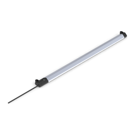
- Page 1 BMP 01- E L1PP _ 1A- _ _ _ _ - 00 -P _ _ -S75 BMP 01- E L1PP _ 1A- _ _ _ _ - 00 -P _ _ -S4 BMP 01- E L1PP _ 1A- _ _ _ _ - 00 -P _ _ User’s Guide english...
- Page 2 www.balluff.com...
- Page 3 Mounting to a pneumatic cylinder using a T- or C-Slot Mounting to a round cylinder Mounting with floating target Electrical connection Cable routing Startup Starting up the system Operating notes Analog interface and switching output Voltage Output 0…10 V Current Output 4…20 mA Switching output Settings using the button www.balluff.com english...
- Page 4 BMP 01-EL1PP _ 1A- _ _ _ _ -00 -P _ _ /P _ _ -S4/P _ _ -S75 Magnetic Field Positioning System IO-Link interface Communication parameters Process data (PD) Identification data System commands Parameter data 7.5.1 Measurement value configuration (MDC) 7.5.2 Switching signal configuration (SSC) 7.5.3 Output configuration 7.5.4 Diagnostic suppression 7.5.5 Temperature detection 7.5.6 Threshold values for the temperature warning...
- Page 5 Condensed guide IODD IO device description Process data The target and mounting accessories depend MDC Measurement data channel on the application and are to be ordered sepa- Switching signal channel rately. Approvals and markings UL approval File no. E227256 www.balluff.com english...
- Page 6 Flawless function in accordance with the are structured as follows: specifications in the technical data is ensured only when using original Balluff accessories. Use of any other SIGNAL WORD components (with the exception of cylinders) will void the warranty.
- Page 7 Detection range: Range in which the BMP detects the position of the target. It extends beyond the measuring range by 4 mm on both sides. The detection range which goes beyond the measuring range is only output via the IO-Link interface. www.balluff.com english...
- Page 8 BMP 01-EL1PP _ 1A- _ _ _ _ -00 -P _ _ /P _ _ -S4/P _ _ -S75 Magnetic Field Positioning System Structure and function (continued) 3.2.1 Analog and switching output LED display In normal operation, three LEDs indicate the operating Analog output state of the BMP. –...
- Page 9 Only the cylinder which has a permanent magnet installed as the target is eligible when mounting to a pneumatic cylinder. A rotating cylinder head causes inaccuracy that is too large! For fastening screws and slot nuts, see Accessories on page 30. www.balluff.com english...
- Page 10 BMP 01-EL1PP _ 1A- _ _ _ _ -00 -P _ _ /P _ _ -S4/P _ _ -S75 Magnetic Field Positioning System Installation and connection (continued) Mounting to a pneumatic cylinder using a 3. Guide slot nuts into the slot. T- or C-Slot For mounting to a pneumatic cylinder, slot nuts are required (see accessories on page 30).
- Page 11 2. Slide hose clamps over the BMP and the holders. Hose clamp Fig. 4-9: Applying hose clamps 3. Tighten screws of the hose clamps in order to secure the BMP to the round cylinder. Fig. 4-10: Securing hose clamps www.balluff.com english...
- Page 12 BMP 01-EL1PP _ 1A- _ _ _ _ -00 -P _ _ /P _ _ -S4/P _ _ -S75 Magnetic Field Positioning System Installation and connection (continued) Mounting with floating target For inverse mounting, a recess for the button and the LEDs must be provided (for dimensions, For mounting with a floating target, mounting screws are see Fig.
- Page 13 The bending radius for fixed cable routing must be at least triple the cable diameter. Cable length Cable length max. 20 m. Longer cables can also be used for the analog output if external interferences remain ineffective due to the structure, shield or routing. www.balluff.com english...
- Page 14 BMP 01-EL1PP _ 1A- _ _ _ _ -00 -P _ _ /P _ _ -S4/P _ _ -S75 Magnetic Field Positioning System Startup Starting up the system DANGER Uncontrolled system movement When starting up, if the positioning system is part of a control system whose parameters have not yet been set, the system may perform uncontrolled movements.
- Page 15 Before Fig. 6-5: Taught-in switching signal After 4 mA 3.5 mA For the adjustment process, see section 6.4 on Target position page 16. Fig. 6-2: Analog current output For the adjustment process, see section 6.4 on page 16. www.balluff.com english...
- Page 16 BMP 01-EL1PP _ 1A- _ _ _ _ -00 -P _ _ /P _ _ -S4/P _ _ -S75 Magnetic Field Positioning System Analog interface and switching output (continued) Settings using the button The settings made using the button apply to the Legend operation using the analog as well as IO-Link interface.
- Page 17 SSP 3.2 Tab. 7-1: BMP device specification The minimum cycle time of the BMP is 1 ms. The master can increase the cycle time as necessary, and as a result, the cycle time actually used (mastercycletime) depends on the master. www.balluff.com english...
- Page 18 BMP 01-EL1PP _ 1A- _ _ _ _ -00 -P _ _ /P _ _ -S4/P _ _ -S75 Magnetic Field Positioning System IO-Link interface (continued) Process data (PD) In the case of an error, the data is only marked as invalid using the PD Invalid Bit if the device absolutely cannot The BMP variants output a measurement value and supply valid data.
- Page 19 The Application Specific Tag, Function Tag and Location Tag tags offer the ability to assign any max 32-byte string to the IO-Link device. This can only be used for application-specific identification and applied in the parameter manager. The entire object is accessed via subindex 0. www.balluff.com english...
- Page 20 BMP 01-EL1PP _ 1A- _ _ _ _ -00 -P _ _ /P _ _ -S4/P _ _ -S75 Magnetic Field Positioning System IO-Link interface (continued) System commands Different commands are implemented in the BMP that can be reached via parameter System Command on index 2, subindex 0. Once a system command is transmitted to the BMP, the command triggers the desired action, provided that this action is permitted in the current application state.
- Page 21 2 bytes Read/Write 0x000D (13) 0, 1, 2, 3, 4 ProfileCharacteristic (see section 7.5.11) 8 bytes Read Only 0x000E (14) 0, 1, 2, 3 PD Input Descriptor (see section 7.5.12) 9 byte Read Only Tab. 7-6: Parameter data of IO-Link interface www.balluff.com english...
- Page 22 BMP 01-EL1PP _ 1A- _ _ _ _ -00 -P _ _ /P _ _ -S4/P _ _ -S75 Magnetic Field Positioning System IO-Link interface (continued) 7.5.1 Measurement value configuration (MDC) A change to the measurement value configuration influences the switching behavior. The BMP uses the measurement value to transmit the The switching signal configuration (see sec.
- Page 23 TI Result 1 byte Read Only 0x00 (0) = inactive 0x003B (59) 0x11 (17) = Teach In of SP1 successful 0x42 (66) = Teach In of SP2 successful 0x07 (7) = Error Tab. 7-9: Teach In parameter data www.balluff.com english...
- Page 24 BMP 01-EL1PP _ 1A- _ _ _ _ -00 -P _ _ /P _ _ -S4/P _ _ -S75 Magnetic Field Positioning System IO-Link interface (continued) Teach In operation 1. Using Tl Select, select the desired switching signal (1 to 4) 2. Move the target to the switch-on position. 3.
- Page 25 The threshold can be set in the range from –25…+85 °C. If these threshold values are exceeded or not met, the BMP outputs a warning (see Event list on page 27). If the internal temperature of the BMP exceeds 95 °C, error Excess temperature is output. www.balluff.com english...
- Page 26 BMP 01-EL1PP _ 1A- _ _ _ _ -00 -P _ _ /P _ _ -S4/P _ _ -S75 Magnetic Field Positioning System IO-Link interface (continued) 7.5.9 Data storage Index Subindex Name Size Access Values Data Storage Command 1 byte Read/Write 0x0003 (3) The Data Storage parameter is required State Property 1 byte Read Only...
- Page 27 HARDWARE FAULT – There is a problem with the device hardware. Restart the BMP by interrupting the supply. If the event occurs again, the BMP must be replaced. 0x8D07 Error OPEN CIRCUIT AT CURRENT OUTPUT – The analog current output is open, check the installation. Tab. 7-16: Event list www.balluff.com english...
- Page 28 BMP 01-EL1PP _ 1A- _ _ _ _ -00 -P _ _ /P _ _ -S4/P _ _ -S75 Magnetic Field Positioning System IO-Link interface (continued) Device error messages If access is faulty, the device responds with one of the listed error codes. Error code Error message 0×8011 Index not available 0×8012...
- Page 29 42, 74, 106, 138, 170, 202, 234, 266 × 17.5 Load resistance R (Analog I) ≤ 500 Ohm × 9.6 mm Output current (Analog U) ≤ 5 mA Tightening torque 0.1 Nm Load capacity of switching ≤ 100 mA Housing material PA12, aluminum output www.balluff.com english...
- Page 30 BMP 01-EL1PP _ 1A- _ _ _ _ -00 -P _ _ /P _ _ -S4/P _ _ -S75 Magnetic Field Positioning System Accessories Holders for round cylinders Accessories are not included in the scope of delivery and (BAM MC-MP-054-01-R) must be ordered separately. Order code: BAM037Z 2 holders for round cylinders Mounting Set for T-Slot (BAM MC-MP-056-01-2-T5)
- Page 31 Metric values in mm, measuring range 128 mm (0032, 0064, 0096, 0128, 0160, 0192, 0224, 0256) Electrical connection: P02 = PUR cable, 2 m P00,5-S4 = PUR cable, 0.5 m with M12 connector, 4-pin P00,5-S75 = PUR cable, 0.5 m with M8 connector, 4-pin www.balluff.com english...
- Page 32 BMP 01-EL1PP _ 1A- _ _ _ _ -00 -P _ _ /P _ _ -S4/P _ _ -S75 Magnetic Field Positioning System Appendix 11.1 Part label Order code Type Serial number Fig. 11-1: Part label (example) english...
Need help?
Do you have a question about the BMP 01-EL1PP 1A Series and is the answer not in the manual?
Questions and answers