Advertisement
Quick Links
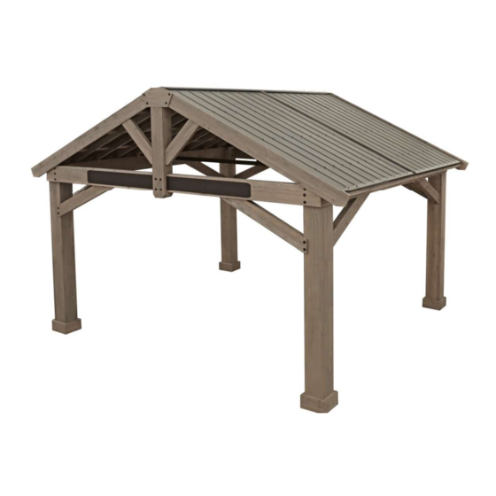
4.9m x 4.3m (16' x 14.1') TIMBER FRAME
PAVILION
Installa on and Opera ng Instruc ons – YM12904
IMPORTANT, RETAIN FOR FUTURE REFERENCE: READ CAREFULLY
Revised 10-13-2022
[4.877 M]
16'
Yardistry – North America
Toll Free Customer Support:
1.888.509.4382
[4.305 M]
14'-1-1/2"
info@yardistrystructures.com
www.yardistrystructures.com
Regular Hours: Mon - Fri, 8:30 am - 5:00
pm EST (excl. holidays)
(For extended hours see our website)
English and French Spoken
Height: 11' 6" (3.51 m)
Patents Pending
Y40000-904
Advertisement

Related Manuals for Yardistry YM12904


Summary of Contents for Yardistry YM12904
- Page 1 4.9m x 4.3m (16’ x 14.1’) TIMBER FRAME PAVILION Installa on and Opera ng Instruc ons – YM12904 IMPORTANT, RETAIN FOR FUTURE REFERENCE: READ CAREFULLY Revised 10-13-2022 [4.877 M] 16’ Yardistry – North America Toll Free Customer Support: 1.888.509.4382 [4.305 M] 14’-1-1/2”...
- Page 2 Wood is NOT fl ame retardant and will burn. Grills, fi re pits and chimineas are a fi re hazard if placed too close to a Yardistry structure. Consult user’s manual of the grill, fi re pit or chiminea for safe distances from combustible materials.
- Page 3 support@yardistrystructures.com...
- Page 4 Instructions for Proper Maintenance Your Yardistry structure is designed and constructed of quality materials. As with all outdoor products it will weather and wear. To maximize the enjoyment, safety and life of your structure it is important that you, the owner, properly maintain it.
- Page 5 Assembly Tips Following are some helpful tips to make the assembly process smooth and effi cient. PRE-ASSEMBLIES: (i.e. Post and Beam Assemblies, Roof Rafter Assembly, etc) • Work on a raised, solid and fl at surface such as, a table or saw horse. •...
- Page 6 Permanent Installation Examples Note: It is critically important you start with square, solid and level footings, concrete pad or deck to attach your Pavilion. We supply Post Mounts with this structure which gives you the fl exibility to permanently install your structure to a pre-existing or new wood or concrete surface.
- Page 7 Permanent Installation Examples cont. Concrete Patio 4.483m x 4.585m (14’ 8-1/2” x 15’ 1/2”) with 15.24cm (6”) clearance on all sides Anchoring Hardware not included Concrete Patio 4.483m x 4.585m (14’ 8-1/2” x 15’ 1/2”) with 15.24cm (6”) clearance on all sides Anchoring Hardware not included Post Mount...
- Page 8 support@yardistrystructures.com...
- Page 9 support@yardistrystructures.com...
- Page 10 support@yardistrystructures.com...
- Page 11 support@yardistrystructures.com...
- Page 12 (Y00441-611) (Y70841-610) support@yardistrystructures.com...
- Page 13 • Please retain this information for future reference. You will need this information if you contact the Consumer Relations Department. PRODUCT NUMBER: YM12904 CARTON I.D. STAMP: __ __ __ __ __ ___ (Box 1) CARTON I.D. STAMP: __ __ __ __ __ ___ (Box 2) CARTON I.D.
- Page 14 Step 2: Post Assemblies A: At the bottom of (1474) 9 x 9 Post, insert eight 5/16” T-Nuts on the outside of each post. (F2.1) B: At the bottom of each Post place four Post Mounts tight to the bottom and inside faces as shown in (F2.1 and F2.2).
- Page 15 Step 3: Front/Back Beam Assembly Part 1 A: Using one Long Beam Insert, connect two (1489) Outer Beam FB at front, and two (1483) Inner Short Beams and one (1486) Inner Centre Beam at back, using twelve 5/16 x 3-1/4” Hex Bolts (with 5/16” lock washer, 5/16” fl at washer and 5/16”...
- Page 16 Step 3: Front/Back Beam Assembly Part 2 B: Install Long Beam Insert on Front/Back Beam Assembly using (12) #8 x 1” Pan Screws as shown in (F3.4 and F3.5). F3.4 Front\ Back Beam Assembly F3.5 #8 x 1” Pan Screws Make sure bolt heads are on the outside of each Beam Assembly...
- Page 17 Step 3: Front\Back Beam Assembly Part 3 C: Flip assembly over so the T-nuts face towards front then fasten assembly with (30) #8 x 2-1/2” Wood Screws through (1483) Inner Short Beam and (1486) Inner Centre Beam. (F3.6, F3.7 and F3.8) D: Repeat for a second Front\Back Beam Assembly.
- Page 18 Step 4: Side Beam Assembly Part 1 A: Connect one (1462) Beam Bottom End to each end of one (1461) Beam Bottom Centre using two 5/16 x 1” Hex Bolts (with 5/16” lock washer, 1/4-5/16” large washer and 5/16” t-nut) per end as shown in (F4.1 and F4.2). B: Connect one (1459) Beam Top RT and one (1460) Beam Top LT using two 5/16 x 1”...
- Page 19 Step 4: Side Beam Assembly Part 2 C: Install eight 5/16” T-Nuts by tapping into the long face of the (1495) Beam Back Centre. Place the board with T-Nuts facing down followed by two (1498) Beam Back End at each end. (F4.3 and F4.4) D: Place two (1471) Beam Block 9”...
- Page 20 Step 4: Side Beam Assembly Part 3 F4.7 (1501) Beam Front (1471) Beam Block 9” (1472) Beam Block 17” 3/8 x 9-1/2” Hex Bolt F4.8 (1473) Beam Block 24” (1472) Beam Block 17” (1471) Beam Block 9” 3/8 x 9-1/2” Hex Bolt Side Beam Insert 3/8 x 9-1/2”...
- Page 21 Step 4: Side Beam Assembly Part 4 F4.11 (1501) Beam (1498) Beam 5/16” Flat Front Back End Washer 5/16” Lock Washer 5/16 x 5-3/4” Hex Bolt 5/16” t-nuts have Beam Side Beam Block Insert been previously installed F4.12 5/16 x 5-3/4” Hex Bolt x8 Hardware 16 x 5/16 x 5-3/4”...
- Page 22 Step 4: Side Beam Assembly Part 5 F4.13 Flush Beam Top Assembly (Part 1 of this Step) F4.14 #8 x 2-1/2” Wood Screws x26 Tight to grooves Hardware 52 x #8 x 2-1/2” Wood Screws support@yardistrystructures.com...
- Page 23 Step 4: Side Beam Assembly Part 6 J: Flip the assembly over and place Beam Bottom Assembly from Part 1 so the groove sits tight and fl ush to the beam assemblies and fasten with (16) #8 x 2-1/2” Wood Screws. (F4.15 and F4.16) Remove the 3/8”...
- Page 24 Step 4: Side Beam Assembly Part 7 F4.17 Side Beam Insert F4.18 5/16 x 3” Lag Screw 5/16” Flat Washer Hardware 2 x 5/16” x 3” Lag Screw (5/16” Flat Washer) support@yardistrystructures.com...
- Page 25 Step 5: Frame Assembly and Anchoring Part 1 A: On a hard fl at surface place one Side Beam F5.1 Assembly against the outside of two Posts, fl ush to the tops and outside corners. The beam sits in the notch out of the Post. Attach Beam to Posts Side Beam Assembly with three 3/8 x 9 1/2”...
- Page 26 Step 5: Frame Assembly and Anchoring Part 2 C: Square the Beam to the Post then attach (1468) Gusset Side using (4) #8 x 3-1/2” Wood Screws per Gusset. (F5.4, F5.5 and F5.6) D: Attach one (1468) Gusset Side per Beam\Post corner joint using two 5/16 x 4-3/4”...
- Page 28 Step 5: Frame Assembly and Anchoring Part 4 H: Make sure each corner is square and level then attach one (1469) Gusset FB Right and (1470) Gusset FB Left to each Front Beam and Post Assembly with two 5/16 x 4” Hex Bolt (with 5/16” fl at washer, 5/16” Lock Washer, 5/16”...
- Page 29 Step 5: Frame Assembly and Anchoring Part 5 Pre drill with 1/8” (3mm) drill bit prior to fastening F5.13 Front Beam F5.14 Assembly Side Beam Assembly 1/4-5/16” Large Washer 5/16 x 4-3/4” Lag Screw Hardware 8 x 5/16 x 4-3/4” Lag Screw (1/4-5/16” Large washer) support@yardistrystructures.com...
- Page 30 Step 6: Centre Truss Assembly Step 6: Centre Truss Assembly Part 1 Part 1 A: Using 5/16” x 1-3/4” Hex Bolts (with two 5/16” Flat Washers and 5/16” Lock Nut) connect two Truss Tie Mount -Tops to the Truss Tie Vertical. The Tie Mount fl anges must run fl at to each other and parallel to the top of Truss Tie Vertical.
- Page 31 Step 6: Centre Truss Assembly Part 2 A: Using four 5/16” x 1-3/4” Hex Bolts (with two 5/16” Flat Washers and 5/16” Lock Nut) connect two Horizontal Truss Assemblies to the Truss Tie Centre Gusset with Truss Tie Centre Gusset fl anges turned inward. (F6.5, F6.6 and F6.7) Note: The fl...
- Page 32 Step 6: Centre Truss Assembly Part 3 A: Using two 5/16” x 6-1/4” Hex Bolts (with two 5/16” Flat Washers and 5/16” Lock Nut) connect Truss Tie Assembly to each Side Beam at the centre. (F6.8 and F6.9) Note: The centre of the Truss Tie Assembly projects upward. (F6.8) F6.8 F6.9 5/16 x 6-1/4”...
- Page 33 Step 7: Upright Assembly A: Create two Upright Assemblies taking one (1504) Front Upright, one (1463) Upright Back and placing them on either side of the Front Beam Assembly. (1504) Front Upright faces outward while (1463) Upright Back faces inward. Fasten to the Front Beam using (4) 5/16” x 6-1/2” Hex Bolts (1/4-5/16” Large Flat Washers, 5/16” Lock washer, 5/16”...
- Page 34 Step 8: Frame Left Roof Panel Part 1 A: Lay out fi ve (1457) Common Rafters and one (1456) Centre Rafter on a hard fl at surface as shown in F8.1. B: Place one (1452) Bottom Rafter on the bottom of the one (1456) Centre Rafter and fi ve (1457) Common Rafter fl...
- Page 35 Step 8: Frame Right Roof Panel Part 2 D: Lay out fi ve (1457) Common Rafters and one (1456) Centre Rafter on a hard fl at surface as shown in F8.4. E: Place one (1452) Bottom Rafter on the bottom of the one (1456) Centre Rafter and fi ve (1457) Common Rafter fl...
- Page 36 Step 8: Frame Roof Panel Part 3 G: Place three (1455) Straps onto all supporting rafters and make sure the assembly is square, then attach (1455) Straps with twelve #8 x 1-1/2” Wood Screws per board. Keep strap ends fl ush to rafters. Repeat step for remaining roof panels.
- Page 37 Step 8: Frame Roof Panel Part 4 J: Use two 1/4 x 5” Hex Bolts per Ridge as a guide to line up (1458) Ridge Short and (1454) Ridge Long to one Left Roof Panel and Right Roof Panel with brackets. Remove each Hex Bolt at the end of this step, as they will be used in a later step and not installed here.
- Page 38 STOP STOP STOP STOP INSTALLING ROOFING MATERIAL CAUTION! Roofi ng material may have sharp edges! Wear gloves! HANDLE WITH CARE! Place roofi ng material on a non-abrasive surface before assembly as it can bend, dent and scratch easily. WARNING – DO NOT OVER TIGHTEN ROOFING SCREWS! Over tightening screws will cause roofi...
- Page 39 STOP STOP STOP STOP INSTALLING ROOFING MATERIAL CAUTION! Roofi ng material may have sharp edges! Wear gloves! BE SURE TO REMOVE ALL PLASTIC COVERING, ON BOTH SIDES OF THE ALUMINUM PANELS AND TRIM, DIRECTLY BEFORE INSTALLING EACH PIECE. (One side is clear and the other is blue, both must be removed.) Example #1 Example #2...
- Page 40 Step 9: Attach Roof Panels Part 1 Important! Before starting this step be sure to refer back to pages 38 and 39 regarding correct installation and handling of roofi ng. A: Make sure panel is still square then on one Roof Panel Frame place one Roof Panel fl ush to the (1453) Top Rafter and sides of the outside (1456/1457) Rafter.
- Page 41 Step 9: Attach Roof Panels Part 2 E: Place Roof Edge on the bottom of each Roof Panel Frame so the holes line up to the roof panel. Predrill the two end holes with a 1/8” drill bit then attach Roof Edges with 11 #8 x 1” Hex Roofi ng Screws. (F9.5) Be sure not to overtighten screws.
- Page 42 Step 9: Attach Roof Panels Part 3 Ridge Clip Top H: Place Weather Seal on the inside of each Ridge Clip, then make fl ush to each side of Roof Panel Frame and 2 3/4” (6.99cm) up from the bottom of (1452) Bottom Rafter. Attach with fi ve #7 x 3/4” Wood Screws per Ridge Clip.
- Page 43 Step 10: Attach Roof Panels to Frame Part 1 A: With four assemblers lift the Right Roof Panel Frame with the Roof Ridges installed, up and over the pavilion frame so it rests on (1504) Upright Assembly and Centre Truss Assembly. The notches in the rafters sit tight on the Side Beam Assemblies.
- Page 44 Step 10: Attach Roof Panels to Frame Part 2 C: From inside the assembly attach one Roof Panel Frame that has the (1454) Ridge Long and (1458) Ridge Short attached, and one Roof Panel Frame without and fasten together through the (1453) Rafter Top with six 1/4 x 5”...
- Page 45 Step 10: Attach Roof Panels to Frame Part 3 D: Place one Left Roof Panel assembly with Roof Ridges installed next to the previously attached Right Roof Panel and fasten the two Roof Panel Frames together through each (1456) Centre Rafter with three 5/16 x 3-3/4” Hex Bolts (two 1/4-5/16”...
- Page 46 Step 10: Attach Roof Panels to Frame Part 4 F: Slide two Peak Caps over top of the Peak Cap Link, align holes and attach with six 1/4 x 1/2” Pan Bolts (with 1/4” lock nut). (F10.9) G: Insert six Carriage Bolts with Contoured Washers through the top of Peak Cap Assembly. Place one Peak Post Long over each Carriage Bolt and secure with Spring Clips.
- Page 47 Step 10: Attach Roof Panels to Frame Part 5 I: Place the Right Roof Panel without Rafter Brackets in place. Push up on the centre of the Roof Panels so the notches in the rafters are tight to the Side Beam Assembly then align holes in (1456) Centre Rafter of each Roof Panel frame.and attach three 5/16 x 3-3/4”...
- Page 48 Step 10: Attach Roof Panels to Frame Part 6 K: From inside and centre of the assembly, attach the remaining Centre Rafter Bracket to the (1456) Centre Rafter with one 5/16 x 4” Hex Bolt (two 1/4-5/16” large washer and one 5/16” lock nut). (F10.18 and F10.19) L: From inside attach the four remaining Rafter Bracket Long to each (1457) Common Rafter of the Right Roof Panel using one 1/4 x 2-1/4”...
- Page 49 Step 10: Attach Roof Panels to Frame Part 7 M: Check that the Roof Panels are fl ush to the Front Beams at bottom and fl ush at top to the Upright Assembly. With the notches in the rafters tight to the Side Beam Assembly, attach four #10 x 1-1/4” Pan Screws per Rafter Bracket Long and six #10 x 1-1/4”...
- Page 50 Step 11: Attach Ridge Cap Part 1 A: Remove two #8 x 1” Roofi ng Screws from each Roof Edge where each Roof Panel Frame Assembly connect. (F11.1 and F11.2) B: Place one Centre Roof Edge over each connecting seam, tight to Roof Edges and attach with previously removed screws.
- Page 51 Step 11: Attach Peak and Ridge Cap Part 2 C: At each Roof Panel Frame Assembly, slide one Ridge Cap over the Ridge Clips, from the bottom up to the top, with holes in Ridge Cap towards bottom. Slide under Peak Cap Assembly. Attach with two #8 x 3/4” Sheet Metal Screws per Ridge Cap Middle.
- Page 52 Step 12: Secure Roof Peak and Truss Tie Mount A: Insert one 1/4” Nut into each Peak Loop. Be careful nut is loose and will fall out until attached to Carriage Bolt. (F12.2 and F12.3) B: Place one Peak Bracket over each of the carriage bolts, then attach Peak Loop to the carriage bolt and twist to tighten.
- Page 53 Step 13: Attach Fascia A: In between two (1464) Fascia place one (1492) Roof Peak and align bolt holes. Connect together with four 5/16 x 1-3/4” Hex Bolts (1/4-5/16” Large Washer, 5/16” Lock Washer, 5/16” T-nut). (F13.1 and F13.2) B: With a helper place the Fascia and Roof Peak Assembly on top of the Gable Upright Assembly. The bottom of (1464) Fascia to bottom of rafter should measure 2-3/4”...
- Page 54 Step 14: Attach Gable Gussets A: From the inside, attach one (1466) Left Gable Gusset and one (1467) Right Gable Gusset to the (1464) Fascia using two #8 x 2-1/4” Wood Screws per gusset. Make sure gussets sit fl ush and tight to (1464) Fascia’s. (F14.2) B: With the bottom of (1466) and (1467) Left and Right Gable Gussets fi...
- Page 55 Step 15: Attach Plaque and Hooks A: Attach Gazebo ID Plaque to a prominent location on your Pavilion with two #8 x 1” Pan Screws. This provides warnings concerning safety and important contact information. A tracking number is provided to allow you to get critical information or order replacement parts for this specifi...
- Page 56 support@yardistrystructures.com...
- Page 57 NOTES support@yardistrystructures.com...
- Page 58 Hours/ Heures/ Horas: 8:30 am - 5:00 pm EST (excl. holidays/ hors jours fériés/ excepto los días fes vos English and French Spoken / Anglais et français parlés / Inglés y francés hablado...
Need help?
Do you have a question about the YM12904 and is the answer not in the manual?
Questions and answers