Advertisement
Quick Links
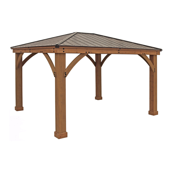
3.6m x 3.06m (12' x 10') WOOD GAZEBO
with ALUMINUM ROOF
Installation and Operating Instructions – YM12935
IMPORTANT, RETAIN FOR FUTURE REFERENCE: READ CAREFULLY
YM12935 - 12 x 10 Gazebo
Revised 11-25-2020
3.671
12'0.5"
3.670 m
12' 1/2"
Yardistry – North America
Toll Free Customer Support:
1.888.509.4382
3.061 m
3.061
info@yardistrystructures.com
10' 1/2"
10'0.5"
www.yardistrystructures.com
Regular Hours: Mon - Fri, 8:30 am - 5:00
pm EST (excl. holidays)
(For extended hours see our website)
English and French Spoken
HEIGHT:
2.896 m / 9'6"
Patents Pending
Height 9 feet 6 inches
Y40000-935
Advertisement

Related Manuals for Yardistry YM12935


Summary of Contents for Yardistry YM12935
- Page 1 3.6m x 3.06m (12’ x 10’) WOOD GAZEBO with ALUMINUM ROOF Installation and Operating Instructions – YM12935 IMPORTANT, RETAIN FOR FUTURE REFERENCE: READ CAREFULLY YM12935 - 12 x 10 Gazebo Revised 11-25-2020 3.671 12'0.5" 3.670 m 12’ 1/2” Yardistry – North America Toll Free Customer Support: 1.888.509.4382...
-
Page 2: Important Safety Notice
Wood is NOT flame retardant and will burn. Grills, fire pits and chimineas are a fire hazard if placed too close to a Yardistry structure. Consult user’s manual of the grill, fire pit or chiminea for safe distances from combustible materials. - Page 3 Limited Warranty Yardistry warrants that this product is free from defect in materials and workmanship for a period of one (1) year from the original date of purchase. In addition, for any product with lumber, all lumber is warranted for five (5) years against rot and decay. This warranty applies to the original owner and registrant and is non-transferable.
-
Page 4: Instructions For Proper Maintenance
Instructions for Proper Maintenance Your Yardistry structure is designed and constructed of quality materials. As with all outdoor products it will weather and wear. To maximize the enjoyment, safety and life of your structure it is important that you, the owner, properly maintain it. -
Page 5: Assembly Tips
Assembly Tips Following are some helpful tips to make the assembly process smooth and efficient. PRE-ASSEMBLIES: (i.e. Post and Beam Assemblies, Roof Rafter Assembly, etc) • Work on a raised, solid and flat surface such as, a table or saw horse. •... - Page 6 Refer to your local building and city codes, ordinances, neighbourhood covenants, or height restrictions regarding this type of structure for guidance on acceptable installation requirements. Concrete Footer Anchoring Hardware not included YM12935 - 12 x 10 Gazebo Post Mount Required Depth 3.401...
- Page 7 Permanent Installation Examples cont. Concrete Patio [min. 3.705 m x 3.096 m (12’1-7/8” x 10’1-7/8”)] with 15.24 cm (6”) clearance on all sides Anchoring Hardware not included Wood Deck [min. 3.705 m x 3.096 m (12’1-7/8” x 10’1-7/8”)] with 15.24 cm (6”)clearance on all sides Anchoring Hardware not included Post Mount Anchoring Hardware (not included)
-
Page 8: Part Identification
Part Identification ( Dimensions are approximate and are shown to assist in the identification of parts for assembly. Actual dimensions may be smaller or larger. 4pc. (1100) - Post 2247.9mm (88½") Y70229-1100 4pc. (739) - Short Left Gusset 926.9mm (36-1/2") Y70229-739 4pc. - Page 9 Part Identification ( Dimensions are approximate and are shown to assist in the identification of parts for assembly. Actual dimensions may be smaller or larger. 2pc. (1085) - Long Strap 2233.6mm (87-15/16") Y50229-1085 2pc. (939) - Strap Long 1721.9mm (67-13/16") Y50229-939 2pc.
-
Page 10: Hardware Identification
Hardware Identification ( Dimensions are approximate and are shown to assist in the identification of parts for assembly. Actual dimensions may be smaller or larger. 12pc. 1/4 x 2-3/4 Hex Bolt - (Y07718-223) 5/16 x 1-1/4" 32pc. Hex Bolt - (Y07718-311) 14pc. - Page 11 Hardware Identification ( Dimensions are approximate and are shown to assist in the identification of parts for assembly. Actual dimensions may be smaller or larger. 4pc. - Short Panel Left 4pc. - Long Panel Right (Y01030-223) (Y01030-224) 2pc. - Middle Panel (Y01030-363) 1pc.
- Page 12 • Please retain this information for future reference. You will need this information if you contact the Consumer Relations Department. PRODUCT NUMBER: YM12935 CARTON I.D. STAMP: __ __ __ __ __ ___ (Box 1) CARTON I.D. STAMP: __ __ __ __ __ ___ (Box 2) CARTON I.D.
- Page 13 Step 2: Post Assemblies Part 1 A: At the bottom of each (1100) 6 x 7 Post insert one 5/16” T-Nut on the outside of each short side. (F2.1 and F2.2) B: At the bottom of each post place two Post Mounts tight to the bottom and inside faces on the short sides as shown in F2.1 and F2.2.
- Page 14 Step 2: Post Assemblies Part 2 C: Flush to the bottom of each (1100) 6 x 7 Post place one (1090) Long Plinth on each long side and one (1089) Plinth on each short side then attach with four #8 x 1-1/2” Wood Screws per plinth. Rounded edges on top. (F2.3, F2.4 and F2.5) There will be four Post Assemblies.
- Page 15 Step 3: Short Beam Assembly Part 1 A: Connect one (1076) Left Outside Beam and one (1077) Right Outside Beam using two 5/16 x 1-1/4” Hex Bolts (with 5/16” lock washer, 1/4-5/16” large washer and 5/16” t-nut) as shown in F3.1 and F3.2. B: Connect one (1078) Inside Short Beam to each end of one (1093) Inside Beam using two 5/16 x 1-1/4”...
- Page 16 Step 3: Short Beam Assembly Part 2 D: Place one Outside Short Beam Assembly tight to one Short Beam End Assembly so the ends are flush. Match the bolt holes in each (1078) Inside Short Beam and (1093) Inside Beam with the bolt holes in (1076) Left Outside Beam and (1077) Right Outside Beam.
- Page 17 Step 4: Long Beam Assembly Part 1 A: Connect one (1095) Right Outside Beam Long and one (1096) Left Outside Beam Long using two 5/16 x 1-1/4” Hex Bolts (with 5/16” lock washer, 1/4-5/16” large washer and 5/16” t-nut) as shown in F4.1 and F4.2. B: Connect one (1094) Inside End Beam to each end of one (1079) Inside Beam Long using one 5/16 x 1-1/4”...
- Page 18 Step 4: Long Beam Assembly Part 2 D: Place one Outside Long Beam Assembly tight to one Long Beam End Assembly so the ends are flush. Match the bolt holes in each (1094) Inside End Beam and (1079) Inside Beam Long with the bolt holes in (1095) Right Outside Beam Long and (1096) Left Outside Beam Long.
- Page 19 Step 5: Frame Assembly Part 1 - Short Side A: On a hard, flat surface place one Short Beam F5.1 Assembly against the outside of two Post Assemblies Short Beam on the short sides, flush to the tops and outside corners. Assembly Notice bolt holes are towards the bottom.
- Page 20 Step 5: Frame Assembly Part 2 - Short Side Note: The bevelled ends on each gusset Short Beam should always face away from the wood it is Assembly F5.4 attaching to. C: Make sure each Short Side assembly is square with the Post Assemblies then facing one Short Beam Assembly from the outside place one (740) Short Right Gusset on the (740) Short...
- Page 21 Step 5: Frame Assembly Part 3 - Short Side E: Make sure the assembly is still square then in the top hole of the Short Beam Assembly attach to Post Assembly with one 5/16 x 4-3/4” Lag Screw (with 1/4-5/16” large washer) per end. (F5.6 and F5.7) F: Repeat Steps C - E for second Short Side Assembly.
- Page 22 Long Beam Left Gusset per Long Beam Assembly. (F6.1 and F6.2) Assembly 3/8” Lock 5/16” T-nut 1/4-5/16” Large Washer 3/8” Large Washer YM12935 - 12 x 10 Gazebo F6.2 5/16” Lock Washer Short Side Assembly 5/16 x 3-1/4” Tight Hex Bolt F6.3...
- Page 23 Step 6: Frame Assembly Part 2 - Long Side E: Make sure the assembly is still square then in the bottom holes of the Long Beam Assemblies attach to Post Assemblies with one 5/16 x 4-3/4” Lag Screw (with 1/4-5/16” large washer) per end. (F6.4 and F6.5) F: Depending on what you are placing the Gazebo on will determine how you anchor it to that surface.
- Page 24 4- 5/16 Large Flat Washer Step 7: Fascia Beam Assemblies A: Tightly connect one (1083) Fascia Left Short and one (1082) Fascia Right Short using one 5/16 x 1-1/4” Hex Bolt (with 5/16” lock washer, 1/4-5/16” large washer and 5/16” t-nut) as shown in F7.1 and F7.2. Repeat to make 2- Fascia Right Short a second Fascia Beam Assembly.
- Page 25 Step 8: Small Roof Rafter Assembly Part 1 A: On each side of one (1088) Rafter place one (1080) LT Corner Rafter and one (1081) RT Corner Rafter so the tops and edges are flush then attach with two #8 x 2” Wood Screws per side. (F8.1 and F8.2) B: Place Fascia Beam Assembly from Step 7A on the bottom of (1080) LT Corner Rafter, (1081) RT Corner Rafter and (1088) Rafter so the sides are flush then attach with two #8 x 2”...
- Page 26 Step 8: Small Roof Rafter Assembly Part 2 D: Place one (1084) Short Strap in the notches of (1080) LT Corner Rafter, (1081) RT Corner Rafter and (1088) Rafter so the ends do not overhang the outside edges of the outside boards then attach with six #8 x 1-1/2” Wood Screws.
- Page 27 Step 9: Attach Rafter Beam Brackets - Small Roof Rafter Assembly A: On the Back of one Small Roof Rafter Assembly place one Rafter Beam Bracket on (1086) Rafter Short Right, (1087) Rafter Short Left and (1088) Rafter. Loosely attach each bracket to rafters with one 1/4 x 2” Hex Bolt (with two 1/4-5/16”...
- Page 28 Step 10: Large Roof Rafter Assembly Part 1 A: On each side of one (1097) Top place one (1088) Rafter so the tops and edges are flush then attach with two #8 x 2-1/4” Wood Screws per side. (F10.1 and F10.2) B: Place Large Fascia Beam Assembly from Step 7B on the bottom of (1088) Rafters so the sides are flush and holes are centred on the (1088) Rafters then attach with two #8 x 2-1/4”...
- Page 29 Step 10: Large Roof Rafter Assembly Part 2 D: Beside each (1088) Rafter place one (1080) LT Corner Rafter and one (1081) RT Corner Rafter so the tops and edges are flush and the bottom edges are flush to Large Fascia Beam Assembly then attach with two #8 x 2-1/4”...
- Page 30 Step 10: Large Roof Rafter Assembly Part 3 F: Place one (939) Strap Long in the notches of (1080) LT Corner Rafter, (1081) RT Corner Rafter and both (1088) Rafters so the ends do not overhang the outside edges of the outside boards then attach with eight #8 x 1-1/2” Wood Screws.
- Page 31 Step 11: Attach Rafter Beam Brackets - Large Roof Rafter Assembly A: On the Back of both Large Roof Rafter Assemblies place one Rafter Beam Bracket on (1086) Rafter Short Right, (1087) Rafter Short Left and both (1088) Rafters. Loosely attach each bracket to rafters with one 1/4 x 2” Hex Bolt (with two 1/4-5/16”...
-
Page 32: Handle With Care
STOP STOP STOP STOP INSTALLING ROOFING MATERIAL CAUTION! Roofing material may have sharp edges! Wear gloves! HANDLE WITH CARE! Place roofing material on a non-abrasive surface before assembly as it can bend, dent and scratch easily. WARNING – DO NOT OVER TIGHTEN ROOFING SCREWS! Over tightening screws will cause roofing material to crush. - Page 33 STOP STOP STOP STOP INSTALLING ROOFING MATERIAL CAUTION! Roofing material may have sharp edges! Wear gloves! BE SURE TO REMOVE ALL PLASTIC COVERING, ON BOTH SIDES OF THE ALUMINUM PANELS AND TRIM, DIRECTLY BEFORE INSTALLING EACH PIECE. (One side is clear and the other is blue, both must be removed.) Example #1 Example #2 Overtightened and Crushed...
- Page 34 Step 12: Attach Roof Panels - Small Roof Part 1 A: Place one Long Panel Left on the front of one Small Roof Rafter Assembly so it is flush to the side of (1080) LT Corner Rafter and a slight overhang at the bottom of the Fascia Beam Assembly. Holes should line up with (1088) Rafter.
- Page 35 Step 12: Attach Roof Panels - Small Roof Part 2 E: Place one Short Panel Left on Small Roof Rafter Assembly so it overlaps the Long Panel Left and it is flush to the sides of (1080) LT Corner Rafter and a slight overhang at the bottom of the Fascia Beam Assembly. There should be no overhanging at the corners.
- Page 36 Step 13: Attach Ridge Clips and Roof Edges - Small Roof A: Place one Roof Edge Left 59-3/4 and one Roof Edge Right 59-3/4 on the bottom of each Small Roof Rafter Assembly so the ends are flush with the outside ends of the Fascia Beam Assembly and meet tight in the centre. Attach both Roof Edges with 13 #8 x 1”...
- Page 37 Step 14: Attach Roof Panels - Large Roof Part 1 A: Place one Middle Panel on the front of one Large Roof Rafter Assembly so it slightly overhangs the top of (1097) Top and an overhang at the bottom of the Large Fascia Beam Assembly. Holes should line up with (1088) Rafter and (939), (1098) and (1099) Straps (F14.1) B: Place one Long Panel Left and one Long Panel Right on each side of Middle Panel so they overlap the Middle Panel and are flush to the sides of (1080) LT Corner Rafter and (1081) RT Corner Rafter and an...
- Page 38 Step 14: Attach Roof Panels - Large Roof Part 2 C: Place one Short Panel Left so it overlaps the Long Panel Left and it is flush to the sides of (1080) LT Corner Rafter and one Short Panel Right so it overlaps the Long Panel Right and it is flush to the side of (1081) RT Corner Rafter.
- Page 39 Step 14: Attach Roof Panels - Large Roof Part 3 1- Spacer Top F: On one Large Roof Rafter Assembly place one (936) Spacer flush to the outside edges and centred on #8 x 2-1/4” Wood Screw (1097) Top then attach with six #8 x 2-1/4” Wood Screws. (F14.5 and F14.6) (936) Spacer #8 x 2-1/4”...
- Page 40 Step 15: Attach Ridge Clips and Roof Edges - Large Roof A: Place one Roof Edge Left 59-3/4 and one Roof Edge Right 83-3/4 on the bottom of each Large Roof Rafter Assembly so the ends are flush with the outside ends of the Large Fascia Beam Assembly and meet tight in the centre.
- Page 41 Step 16: Attach Roof Panels to Frame Part 1 A: From inside the Post Assemblies measure 4’15/16’ (1.24 m) to mark the centre of each Short Beam Assembly. (F16.1) B: With all four assemblers place Small Roof Panel Assembly with Rafter Beam Brackets just in front of the Posts then raise it up so it is over Short Beam Assembly, taking care not to drag the panel on the beams.
- Page 42 Step 16: Attach Roof Panels to Frame Part 2 C: Lift a Large Roof Panel Assembly with Rafter Beam Brackets over Long Beam Assembly taking care not to drag the panel on the beams. Make sure the Rafter Corners are flush with each other. One person must remain on the centre ladder to hold both panels in place until three panels are up and secure.
- Page 43 Step 16: Attach Roof Panels to Frame Part 3 E: Lift second Large Roof Panel Assembly with Rafter Beam Brackets over Large Beam Assembly taking care not to drag the panel on the beams then set in place beside the Small Roof Panel Assembly. (F16.5) F: Starting at the bottom and working up connect Large Roof Panel Assembly to Small Roof Panel Assembly through the Rafter Corners with three 1/4 x 2-3/4”...
- Page 44 Step 17: Roof Peak Assembly A: Insert two Carriage Bolts with Contoured Washers through the top of Peak Cap Long, into Peak Post then Spring Clip. The Spring Clip holds the assembly together. (F17.1 and F17.2) B: Insert one 1/4” Nut into each Peak Loop. Be careful nut is loose and will fall out until attached to Peak Cap Assembly.
- Page 45 Step 18: Attach Roof Peak to Roof Panels A: Insert Roof Peak Assembly in gap between Large and Small Roof Panels. Peak Cap Long to be lined up with Rafter Corners. (F18.1 and F18.2) B: Insert two Roof Peak Brackets through each Carriage Bolt and attach Peak Loop to Carriage Bolts then twist to tighten loosely.
- Page 46 Step 19: Attach Final Roof Panel Part 1 A: Lift last Small Roof Panel Assembly (without Rafter Beam Brackets) over Short Beam Assembly taking care not to drag the panel on the beams. Panel fits under the Peak Cap Long, push up on Peak Loop to lift Peak Cap Long.
- Page 47 Step 19: Attach Final Roof Panel Part 2 Remember to push up centre to assist with alignment. B: Starting at the bottom and working up loosely connect Roof Panel Assemblies through the Rafter Corners with three 1/4 x 2-3/4” Hex Bolts (with two 1/4-5/16” large washers and one 1/4” lock nut) per side. To align bolt holes helper on the centre ladder may have to push up in the centre of the panels and others make sure corners are aligned.
- Page 48 Step 19: Attach Final Roof Panel 3- Rafter to Beam Brackets Part 3 3- 1/4 x 2" Hex Bolts C: On the Small Roof Rafter Assembly just installed, place one Rafter Beam Bracket on each (1086) Rafter Short Right, (1087) Rafter Short Left and (1088) Rafter. Loosely attach each bracket to rafters with one 1/4 x 2” Hex 3- 1/4 Lock Nut Bolt (with two 1/4-5/16”...
- Page 49 Step 20: Secure Roof Corners A: Make sure middle Rafter Beam Brackets are lined up over centre mark and all are flush and tight to the Beam Assemblies. Lift in centre if needed to adjust Roof Panel Assemblies. B: From outside the assembly attach Roof Panel Assemblies together at the Fascia Beam Assembly Ends with two #8 x 2-1/4”...
- Page 50 Step 21: Attach Corner and Beam Caps A: At each corner place one Corner Cap tight to Fascia Assemblies, push up so the bottom is tight to the bottom of the assemblies then attach with four #8 x 3/4” Sheet Metal Screws per Corner Cap. (F21.1 and F21.2) F21.1 F21.2 #8 x 3/4”...
- Page 51 Step 22: Secure Rafter Beam Brackets A: From inside the assembly attach Rafter Beam Brackets to beams and rafters with four #10 x 1-1/4” Pan Screws per bracket. (F22.1 and F22.2) B: Tighten all bolts in Rafter Beam Brackets. (F22.1 and F22.2) F22.1 Inside View Roof Panel...
- Page 52 Step 23: Secure Roof Peak Brackets A: Tighten the six screws in Roof Peak Brackets then attach to Corner Rafters in the remaining holes with ten #10 x 1-1/4” Pan Screws. (F23.1) F23.1 Roof Peak Bracket Corner Corner Rafter Rafter Corner Rafter Corner...
- Page 53 Step 24: Attach Ridge Caps to Roof Panels A: Slide one Ridge Cap 85 over each Ridge Clip 85.25, with cut end leading, on each corner of the assembly from the bottom up, lifting Peak Cap by pushing up the Peak Loop so Ridge Caps fit under Peak Cap Long then attach with two #8 x 3/4”...
- Page 54 Step 25: Attach Tie Wrap Brackets and Ties A: Attach one Tie Wrap Bracket to each end of F25.1 Large Roof Panel Large Roof one (961) Tie with one #10 x 1-1/4” Pan Screw Panel per bracket using the inside holes. (961) Tie is tight to end of bracket.
- Page 55 Step 26: Attach Twist Brackets A: Measure 4-1/2” (11.43 cm) down from the inside of each post, place bottom of 45° Twist Bracket LT or 45° Twist Bracket RT at measured location then attach to posts and LT Corner Rafters and RT Corner Rafters with four #10 x 1-1/4”...
- Page 56 Step 27: Metal Hooks and Plaque A: Two 50 mm Hooks are included with this unit for attaching wiring. They can be placed anywhere along the Corner Rafters as needed. Pre-drill with a 1/8” drill bit before installing. (F27.1 and F27.2) B: Attach Gazebo ID Plaque to a prominent location on your gazebo with two #8 x 1”...
- Page 57 Yardistry 375 Sligo Road West, P.O. Box 10, Mount Forest, ON Canada N0G 2L1 ® Distributed by: Costco Wholesale Canada Ltd.* Importado por: Costco Wholesale Australia Pty Ltd Costco Wholesale Corporation 415 W. Hunt Club Road Importadora Primex S.A. de C.V.
- Page 58 NOTES support@yardistrystructures.com...
- Page 59 NOTES support@yardistrystructures.com...
- Page 60 Anglais et français parlés / Inglés y francés hablado À l’attention de: Service à la clientèle Yardistry would like to say “Thank you” for your time and feedback. Yardistry quiere “Agradecerle” por su tiempo y su opinión. Yardistry aimerait vous remercier d’avoir pris le temps de répondre au sondage.
Need help?
Do you have a question about the YM12935 and is the answer not in the manual?
Questions and answers