Advertisement
Quick Links
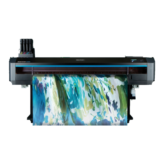
XPJ-1642WR
Startup Guide
Unpacking and Initial Setup
• Unauthorized copying or duplication of the whole or part of the contents of this Guide is prohibited.
• Every care has been taken in writing the contents of this Guide, but please contact MUTOH or the dealer you purchased the
product from if you find any unclear, erroneous or otherwise unsatisfactory content in the Guide.
• Please be aware that MUTOH will not be liable in any way for failures or accidents that result from handling or operating the
printer according to any procedures other than those set forth in this Guide.
• Company names and product names that appear in this Guide are registered trademarks of the respective companies.
Site Preparation . . . . . . . . . . . . . . . . . . . . . . . . . . . . . . . 2
Unpacking . . . . . . . . . . . . . . . . . . . . . . . . . . . . . . . . . . . . 4
Assembling . . . . . . . . . . . . . . . . . . . . . . . . . . . . . . . . . . . 8
Connecting Power and Network . . . . . . . . . . . . . . . 14
Printer Initial Setup . . . . . . . . . . . . . . . . . . . . . . . . . . . 16
Test printing . . . . . . . . . . . . . . . . . . . . . . . . . . . . . . . . . 25
Installing MUTOH Status Monitor . . . . . . . . . . . . . . 37
Safety Precautions . . . . . . . . . . . . . . . . . . . . . . . . . . . . 38
Advertisement

Related Manuals for Muton XPJ-1642WR


Summary of Contents for Muton XPJ-1642WR
-
Page 1: Table Of Contents
XPJ-1642WR Startup Guide Unpacking and Initial Setup Site Preparation ....... 2 Unpacking . -
Page 2: Site Preparation
Site Preparation Site Preparation Choose the location which satisfies the requirements below. Installation Location Requirements • The floor must be level. • Avoid vibration from the neighboring devices. • Low humidity and free from dust. • Less chance of temperature and humidity changes. •... - Page 3 The installation site must meet the power specification and environmental requirements below. Power Specification • Input voltage: AC 100V to 120V±10% AC 200V to 240V±10% • Input frequency: 50 / 60Hz ±1Hz • Input load current: 11.5 A (AC 100V to 120V) 6.0 A (AC 200V to 240V) Environmental Requirements •...
-
Page 4: Unpacking
Unpacking Unpacking Before unpacking, read the instructions below and prepare the necessary items. Unpacking Preparation • Minimum 4 people are required for unpacking, assembling and installation. • The items listed below are required for installation and initial setup. *1,*2 Computer : 1 Gigabit Power cord: 1 Roll media : 1... - Page 5 Unpack the product. Unpacking the printer • Minimum four people are required for unpacking and moving this product. CAUTION • When taking out the product from the packing box, remove the plastic sheet wrapped around the product, then take out the product. Failure to do so may cause slip and damage to the product. •...
- Page 6 Check that the following items are included. Request for User Printer : 1 Stand box: 1 Startup Guide : Registration & Download : Japanese/English (each) Japanese/English (each) Cable tie : 1 Cleaning stick : 10 Waste ink tank : 1 Cleaning wiper for head height High (grey): 1 Paper towel : 5 Tweezers : 1 Media flange : 2 Flushing box sponge : 5 *1 Included in the accessory box. 6 Unpacking...
- Page 7 Unpacking Stand Open the packing box and take out the items listed below. Foot (x2) Leg (Right) Brace Leg (Left) Stand box Check that the following items are included. Leg (Left) : 1 Brace : 1 Foot: 2 Leg (Right): 1 Round head screw: 12 Spring washer: 8 Hex head bolt : 8...
-
Page 8: Assembling
Assembling Assembling Follow the steps below to assemble the stand. Assembling Stand Minimum two people are required for assembling the stand. CAUTION Attach the left leg and right leg to the brace. • Face the screw hole face (face with notch) on the brace toward the rear side of the printer and attach it to both legs. •... - Page 9 Use the round head screws (×4) to attach the waste ink tank holder to the right leg. Leg (right) Screws Waste ink tank holder × 4 Shake the stand to make sure that each part is firmly attached. Turn the leveling adjusters (×4) as shown on the left until the stand Stand does not move.
- Page 10 (If you do not have lifting bars) Lift the printer with at least four people and mount it on the stand. • Use the handholds at the front bottom of the printer. Use the wing bolts (×8) and attach the printer to the stand. ×...
- Page 11 Remove packing materials from the product. Removing Packing Materials Remove the protective material at the front cover. Open the front cover and remove the protective tape from the maintenance cover. Remove the protective tape from the cap on the cutter. Assembling 11...
- Page 12 Remove the wing bolt to remove the shipping bracket from the carriage. Important! Keep the shipping bracket and screws for next use. Remove the protective tape, then remove the protective material at the back inside of the printer. Timing fence Important! When removing protective materials, do not touch the timing fence (clear part).
- Page 13 Attach the waste ink tank to the printer. Attaching Waste Ink Tank Place the waste ink tank on the waste ink tank holder. Put the waste ink tube in the mouth of the waste ink tank. Connect the waste ink sensor cable to the waste ink sensor connector. Important! •...
-
Page 14: Connecting Power And Network
Connecting Power and Network Connecting Power and Network Follow the steps below to connect the power cord and Ethernet cable. Connect Power Cord and Ethernet Cable Check that the front cover is closed. Connect the power cord and a Ethernet cable to the printer. 14 Connecting Power and Network... - Page 15 Insert the tip of the cable tie into the hole on the printer to attach it. Use the cable tie to secure the Ethernet cable to the printer. Plug the power cord into the wall outlets respectively. Connecting Power and Network 15...
-
Page 16: Printer Initial Setup
Printer Initial Setup Printer Initial Setup Here is how to get started with your printer. Initial Setup Flow Configure the initial settings Choose and configure the language, unit of length, temperature, and network setting from the front panel. Activate the printer Enter the activation code from the front panel. - Page 17 Power on the printer and configure the initial settings on the front panel. Step 1 Powering on - Initial settings on the front panel Check that the front cover is closed. Long press the Power button on the front panel. •...
- Page 18 Sets the gateway. Gateway : • key: Increase the number. 192. 168. • key: Decrease the number. • key: Move the cursor to the previous digit. • key: Move the cursor to the next digit. (Enter) after entering each digit. The printer will start mechanical initialization.
- Page 19 Activation through the front panel When the message on the left appears, tap (Enter). Activation required Enter the 16-digit activation code. 0 0 0 0 - 0 0 0 0 - 0 0 0 0 - 0 0 0 0 •...
- Page 20 Follow the steps below to perform initial ink charging. Step 3 Initial Ink Charging Items Required: • Ink bag: ×4 Black, Cyan, Magenta, Yellow • Ink bag case: ×4 Important! When performing initial ink charging, make sure that the head height is set to "Low1" (factory default). Perform initial ink charging Ink Charge When the message on the left appears, tap...
- Page 21 When installing 1,000 ml ink bag cases. Prepare the new ink bag and follow the instructions below to invert it 3 sec. to mix the ink. • Face the ink spout side upwards for 3 seconds. • Invert it and count for 3 seconds. •...
- Page 22 Apply an ink color label onto the outside of the case. Note • The label should be applied in the label application area (within the recess on the outside of the case) as shown in the illustration left. • Make sure to match the color of the label with the one applied onto the inside of the case.
- Page 23 When installing 2,200 ml ink bag cases. Prepare the new ink bag and follow the instructions below to invert it 3 sec. to mix the ink. • Face the ink spout side upwards for 3 seconds. • Invert it and count for 3 seconds. •...
- Page 24 Insert the ink bag cases and S/C cards into each slot. • Make sure to match the colored label on the ink slot and the colored label on the ink bag. • Face the latch side towards you and insert the case into the slot. •...
-
Page 25: Test Printing
Test printing Test printing Follow the steps below to load a media into the printer. Important! Depending on the size of media, two or more people are required. Load a roll media into the printer Attach flanges to the media Items Required: •... - Page 26 Twist the handle clockwise to lock the flange. Important! Check that the flange is firmly locked. If not, the media can be removed from the flanges, affecting the print quality. Enable torque on media holders If you want to apply torque to the media holders, follow the steps below. Twist the knob bolt on the right side of the media holder anticlockwise to loosen.
- Page 27 (When looking from the rear side of the printer) Use the screwdriver to loosen two screws securing the roller shaft guide plate to the right media holder. Slide up the roller shaft guide plate as far as it will go and tighten the screws.
- Page 28 Place the media onto the media holder Twist the knob bolt on the right side of the media holder anticlockwise to loosen. Place the roll media onto the left media holder. Carefully and gently place it on the holder. (If torque is enabled) ...
- Page 29 Slide the right side of the media holder to place the right side of the flange onto the holder. Place the roll media onto the right media holder. Carefully and gently place it on the holder. (If torque is enabled) ...
- Page 30 Load the media into the printer Check that the printer is powered on. From the front side of the printer, fully pull the media feed lever towards you to release the pressure rollers. You can access to the media feed lever from the rear side of the printer. •...
- Page 31 While one person holds the front edge of the media, the other person turns the flange to slightly rewind the media onto the roll to remove warp or skew. Note If you remove your hands from the front edge of the media while rewinding, the media can be removed from the media slot. Check that the right-hand edge of the media is located at the left side of the media guide line.
- Page 32 After loading the media... From the front side of the printer, push the media feed lever to hold the media flat with pressure rollers. Note Using this lever, the holddown pressure can be changed between High and Normal. Normally push the lever until it clicks to apply normal pressure. Operation Manual ”Changing holddown pressure using media feed lever”...
- Page 33 Note The way to attach edge holders varies depending on type of roll media to be loaded. Operation Manual ”Swapping left and right edge holders depending on the media type” • Normally attach them as shown in the figure below so that the hole on the edge holder is located on the outside of the holder. This will hold down roll media lightly.
- Page 34 Set the side margin to 10 mm minimum. Side Margin : • Use to choose the alignment method. (5 - 25) 10 mm (Enter) • Tap Note The side margin can be set between 5 mm and 25 mm depending on type of roll media being loaded: •...
- Page 35 Nozzle Check and Cleaning Run a nozzle check print. If nozzle missing is found, perform cleaning. This printer offers the following 3 kinds of nozzle checks: • Nozzle Check: Print a nozzle check pattern selected from "Setup 29: Select Nozzle. •...
- Page 36 Important! If you run a nozzle check print immediately after the initial ink charging, the following symptoms may occur: • lines are faded. • patterns are partially missing. In such cases, follow the instructions on the operation manual “Menu 3: Cleaning” to perform “Little Charge” . If it does not help to solve the problem, leave the printer for one hour or more, then perform cleaning or “Little Charge”...
-
Page 37: Installing Mutoh Status Monitor
Allows you to view printer status, change printer’s settings and run a test printing. Manuals (for printer and software) The following documents are available in the PDF format. • XPJ-1642WR Operation manual “Operations and Maintenance Methods” • XPJ-1642WR Startup Guide (This manual) • MUTOH Status Monitor Operation manual Important! Make sure to install MSM downloaded from MUTOH Club. -
Page 38: Safety Precautions
Safety Precautions Safety Precautions Important Notice For Users in Europe The CE marking is a mandatory European marking for certain product groups to indicate conformity with the essential health and safety requirements set out in European Directives. By affixing the CE marking, the manufacturer, his authorized representative, or the person placing the product on the market or putting it into service ensures that the item meets all the essential requirements of all applicable EU directives and that the applicable conformity assessment procedures have been applied. - Page 39 Electrical Shock, Short, and Fire Hazard WARNING DO NOT install this product in a location with high Use the designated power cord only. humidity and dust. Failure to do so could result in an electrical shock or fire. This could result in an electrical shock or fire. DO NOT use a damaged power cord.
- Page 40 Installation Precautions WARNING When installing this product, avoid the location where • the floor is not flat and level. • the product gets vibration from the neighboring devices. Failure to do so may result in injury from a fall. CAUTION DO NOT tilt or turn the product upside down.
- Page 41 Product Handling (continued) DO NOT touch the media guide while printing or the The media guide can be very hot immediately after heater is on. printing. The media guide can be very hot, causing burn injuries. Wait until it cools down. DO NOT attempt the following actions during ink DO NOT use volatile chemicals such as thinner, charging:...
- Page 42 Warning Labels Warning labels are applied onto the product where special attention is required. Read the messages on the labels and always follows the instructions. If the labels are peeled off or become dirty, contact your local MUTOH dealer to get new one. CAUTION / ATTENTION / Cut Hazard Label for Steel Belt Sharp Edges.
- Page 43 Protective equipment label (Mask • Glasses • Gloves • Protective clothing) Wear protective equipment when handling ink. Rating plate ”~” on the rating plate represents AC voltage. Note The following marks are for China’s safety standards. Dan hab yungh youq gij digih haijbaz 2000m doxroengz haenx ancienz sawjyungh.
- Page 44 XPJ1642WRE-Q-01...
Need help?
Do you have a question about the XPJ-1642WR and is the answer not in the manual?
Questions and answers