Advertisement
Quick Links
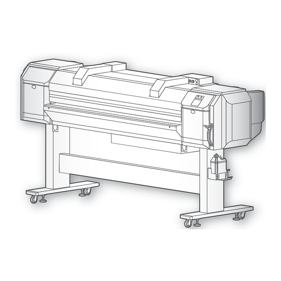
VJ-1627MH
Startup Guide
Unpacking and Initial Setup
• Unauthorized copying or duplication of the whole or part of the contents of this Guide is prohibited.
• Every care has been taken in writing the contents of this Guide, but please contact MUTOH or the dealer you purchased the
product from if you find any unclear, erroneous or otherwise unsatisfactory content in the Guide.
• Please be aware that MUTOH will not be liable in any way for failures or accidents that result from handling or operating the
printer according to any procedures other than those set forth in this Guide.
• Company names and product names that appear in this Guide are registered trademarks of the respective companies.
Unpacking . . . . . . . . . . . . . . . . . . . . . . . . . . . . . . . . . . . . 2
Assembling . . . . . . . . . . . . . . . . . . . . . . . . . . . . . . . . . . . 8
Connecting the cables . . . . . . . . . . . . . . . . . . . . . . . . 20
Setup . . . . . . . . . . . . . . . . . . . . . . . . . . . . . . . . . . . . . . . . 22
Test printing . . . . . . . . . . . . . . . . . . . . . . . . . . . . . . . . . 33
Sleep Mode . . . . . . . . . . . . . . . . . . . . . . . . . . . . . . . . . . 45
Accessing the Manuals . . . . . . . . . . . . . . . . . . . . . . . . 47
Safety Instructions. . . . . . . . . . . . . . . . . . . . . . . . . . . . 48
Advertisement

Related Manuals for Muton ValueJet VJ-1627MH


Summary of Contents for Muton ValueJet VJ-1627MH
-
Page 1: Table Of Contents
VJ-1627MH Startup Guide Unpacking and Initial Setup Unpacking ........2 Assembling . -
Page 2: Unpacking
Unpacking Unpacking • Four or more people are required to unpack and move this printer. CAUTION • Keep this product level when moving it. Unpacking the printer Open the packing box and take out each part. Installation instruction: Startup Guide (this document) Accessory box High capacity ink pack adapter Printer body... - Page 3 Check if the followings are included. Installation Instruction: Instruction sheet Japanese/English (each) for dedicated ink: Daily maintenance sheet: Startup Guide Printer: 1 Software CD: 1 Japanese / English Japanese / English (this document) Paper Towel Plastic gloves: 100 Dropper (5 ml): 2 Plastic cup (100 ml): 2 Cleaning stick: 10 (Lint-free cloth): 5...
- Page 4 Items in the stand box Check if the followings are included. Waste fluid tank Leg part (Left): 1 Leg part (Right): 1 Connector bar: 1 Base part: 2 holder: 1 Hexagon socket Waste fluid tank holder head cap screw: 8 Hexagonal wrench: 1 Butterfly screw: 8 fixing screw: 4...
- Page 5 Things to prepare in order to install and use the printer In order to install the product and make the initial settings, you will need the following things in addition to the packaged items. 500 ml Computer: 1 Ethernet cable: 1 Power cable: 3 Media: 1 Cleaner bag: 7...
- Page 6 Installation location Minimum installation space 4,698 mm Size of printer body 1,000 mm width x depth : 2,698 mm x 818 mm Rear height : 1,302 mm Size of printer body Front 1,000 mm Ensuring a suitable place for installation Install this product in a place that: •...
- Page 7 Installation environment conditions Install the product in an environment that satisfies the conditions in the table below. Power supply Printer Voltage: AC 100 V to 240 V ±10% specifications Frequency: 50/60 Hz ±1 Hz Capacity: No less than 3 A Heater ×2 Voltage: AC 100 V to 120 V ±10% / AC 200 V to 240 V ±10% Frequency: 50/60 Hz ±1 Hz...
-
Page 8: Assembling
Assembling Assembling Assemble the printer Four or more people are required to assemble this printer. CAUTION Procedure for assembling the stand Follow the procedure below to assemble the stand. Assemble the right stand. Attach the right leg part to the right base part so that four screw holes in the base part are at the front. - Page 9 Fasten the connector bar to the left stand in the same way as in Step 5. Stand (left) Connector bar Front Hexagon socket head cap screws Attach the waste fluid tank holder to the right stand using four screws. Stand (right) Screws Waste fluid tank holder Shake the stand to make sure that each part is firmly attached.
- Page 10 Procedure for attaching the waste fluid tank Follow the procedure below to attach the waste fluid tank. Place the waste fluid tank in the waste fluid tank holder. Attach the waste fluid tube to the tank. Waste fluid tube • Attach the waste fluid tube to the tank. •...
- Page 11 Detaching fastening materials Follow the procedure below to detach all protective materials. Remove all tapes from each cover. Open the front cover and remove all protection materials fixed with tape. Peel off the tape, be careful not to come in contact with T fence, and remove the Bearer collapse prevention material and Bearer fix.
- Page 12 Remove a screw from the carriage bracket and then remove the bracket. Close the front cover. Open the right maintenance cover. Remove the cushioning material from the printer. • Close the maintenance cover. [10] Open the left maintenance cover, then place the tray. •...
- Page 13 Checking the levelness Turn the following adjusters in the direction as shown left to prevent the printer from moving. Open the front cover. Set the level on the right and left platens and adjust so that the printer Level stays flat. Assembling 13...
- Page 14 Assembling the media-feed table (optional) To print on a rigid media, follow the steps below to assemble the media-feed tables. Use hexagon socket head cap screws (4 pieces) to fix the Leg (Left) reinforcement between the legs (right and left). Leg (Right) •...
- Page 15 Attaching the media-feed table (optional) Before printing on a rigid media, follow the steps below to install the media-feed tables. Required items: • Hexagonal spanner (supplied with the media-feed table) • Level (supplied with the printer) Rear side procedure Loosen the fixing levers on the right and left side of the rear. Set the distance between the roll media holders wider than the roll media width.
- Page 16 Turn the screws on the caster of Media-feed table (2 places, ones closer to the printer) with a spanner. Adjust so that there is a 6 mm gap between the top side of the square hole of Paper guide R and the top side of the positioning guide.
- Page 17 Turn the screw of Media-feed table’s caster (the one further from the printer) with a spanner, and adjust the slant. Make sure that the position of the level’s air bubble is at the same position as when you place it on the printer. Level Adjust the slant on the other side in the same way.
- Page 18 Turn the screws on the caster of Media-feed table (2 places, closer to the printer) with a spanner. Adjust so that there is a 6 mm gap between the top side of the square hole of Paper guide F and the top side of the positioning guide.
- Page 19 Turn the screw of Media-feed table’s caster (the one further from the printer) with a spanner, and adjust the slant. Make sure that the position of the level’s air bubble is at the same position as when you place it on the printer. Level Adjust the slant on the other side in the same way.
-
Page 20: Connecting The Cables
Connecting the cables Connecting the cables Connecting power cable Before connecting the cables... Close the front cover. Make sure that the printer is turned off. Check! Note If the power switch is in a pressed-inward state, it is turned on and you must press it again to turn it off. - Page 21 Connecting the power cable Connect power cable to the printer. Connect the power cables (×2) to the blower heater. Insert the plug of the power cables correctly in the sockets. Connecting the cables 21...
-
Page 22: Setup
Setup Setup Setup Procedure Perform activation Activate this product from the operation panel. Configuring the initial settings Select the language and units of the operation panel display. Initial Charging Install ink bags into this product and perform ink charging. Loading the media for test printing Set the media to print the nozzle check pattern. - Page 23 Turning the power ON Close the front cover. Turn ON the power switch of blower heater on the rear side of the printer. Turn Link switch of blower heater on the front of the printer to “Printer Link”. • Link switch blinks. Press the power button to turn the power ON.
- Page 24 Perform Activation This product requires activation when you turn the power ON for the first time. When the message on the left appears, carry out activation. Activation required There are two ways of carrying out activation. "To activate via the control panel" P. 24 "To activate via the Internet"...
- Page 25 Configuring the initial settings Configure the initial settings according to the instructions displayed. Configuring the operation panel language and units Press the [Enter] key. Language : English Press the [Enter] key. Length : The printer starts initialization operations. Initializing Setup 25...
- Page 26 Initial ink charging Preparation • Cleaning wiper: 1 • High capacity ink pack adapter: 7 • Cleaning bag: 7 • Ink bag: 7 4 color setting: Magenta (M), Cyan (C): 2 bags each Black (K), Yellow (Y), Cleaning (Cl): 1 bag each 5 color setting: Black (K), Cyan (C), Magenta (M), Yellow (Y), White (Wh): 1 bag each Cleaning (Cl): 2 bags each...
- Page 27 Initial cleaning Press the [Enter] key. Start Ink Charge - > E • Use the [+] or [-] key on Operation panel to select the ink color Ink Comb. : * Color setting. • Press the [Enter] key. Press the [Enter] key. Wash Retry ? Make sure the waste ink tank is empty, and press the [Enter] key.
- Page 28 Insert High capacity ink pack adapters into all the cartridge slots. • Insert each High capacity ink pack adapter to firmly seat it into each slot. The printer starts charging cleaning fluid. Busy-Washing When cleaning fluid charging ends, the message on the left will appear.
- Page 29 Emptying the waste fluid tank WARNING You are obligated to properly dispose of waste fluid from the printer in compliance with Wastes Disposal and Public Cleansing Act and local ordinances. Delegate disposal to an industrial waste disposal contractor. CAUTION Be cautious that ink does not get into your eye or make a contact with your skin. Wear groves. When ink gets into your eye or make a contact with your skin, wash with water immediately.
- Page 30 After pouring the waste fluid to the empty container, close the waste fluid valve securely. Wipe the opening of the waste fluid valve with a cloth, etc. Pull out the absorbent material tray. Absorbent material tray Dispose of the waste fluid as an industrial waste product. 30 Setup...
- Page 31 Initial ink charging The message on the left will appear. Insert InkCartridges Lower the lock lever on the High capacity ink pack adapter and detach the cleaning bag. Remove the S/C card from the High capacity ink pack adapter. Note Once removed, keep the cleaning bag and the smart chip card together in the same place.
- Page 32 Confirm ink bag is fully seated by checking the lock mechanism is at the top of the ink delivery neck through the observation window, see proper placement in illustration left. Good NotGood Make sure that the lock lever of the High capacity ink pack adapter is back to its original position.
-
Page 33: Test Printing
Test printing Test printing Loading a roll media in the printer Important! Depending on the type of the media, we recommend that two or more persons set the media. Loading Roll Media onto the Roll media holder Loosen Fixing levers on the Roll media holders (both left and right) on the back of the printer. - Page 34 Attach Roll media holder (right) to the roll media and tighten Fixing lever. Loosen the Fixing levers of the right and left Roll media holders, move the roll media to the center. Press Roll media holder toward the printer and fix the Fixing levers. Note •...
- Page 35 Raise the media loading lever. Load the roll media to Media feed slot. Note If the end of the roll media is not wound tightly, wind it tightly again, and then load it. Pull the roll media out about 1 m from the front Media feed slot. Turn the flange on the roll media holder to rewind the media while holding the edge of the media, and eliminate any slack or slant.
- Page 36 After loading the media... “Lever Up” is displayed on the Operation panel. Lever Up Lower the media loading lever. Make sure that the edges of the media is appropriately pressed by Pressurizing rollers. Good Good Not Good Pressurizing roller Roll media The edge of the roll media is protruding from the pressurizing roller.
- Page 37 Set the media holder at both edges of the media. Important! With the default settings, the printing operation starts 5 mm from the edge of the media. To hold down the media, make sure that the part overlapping the media is less than 5 mm in length. Close the front cover.
- Page 38 Loading a rigid media in the printer Important! Depending on the type of the media, we recommend that two or more persons set the media. Loading Rigid Media into the printer Make sure that the printer is turned ON. Check! Open the front cover.
- Page 39 Place the rigid media on the rails and tighten the rail retaining screw at where there is a 5 mm gap between the stoppers on both sides and the media. Place the rigid media on Media-feed table (front side) in the same way, and fix the rails at where there is a 5 mm gap between the stoppers on both sides and the media.
- Page 40 After loading the media... “Lever Up” is displayed on the Operation panel. Lever Up Lower the media loading lever. Note Media-feed table is excluded from the illustration for simplicity. Make sure that the edges of the media is appropriately pressed by Pressurizing rollers. More than 50% area of the pressurizing roller on the far left and right should hold down the edge of the media.
- Page 41 Note If the media type is not set to “Rigid”, go to “Menu 2: User Type >” - “User: Type*” - “**> 10: Rigid / Roll” and select “Rigid”. Press the [Enter] key to execute media initialization. • That ends the media loading procedure. Press! Press down the [-] key on Operation panel for a while, and check that the rigid media can be fed no problem.
- Page 42 Nozzle check and cleaning Before starting everyday operation, please perform nozzle check printing to check the print head condition. If nozzle clog is found, perform cleaning. This printer offers the following two kinds of nozzle checks: • Nozzle Check - Prints the nozzle check patterns. •...
- Page 43 Note The figure below are examples of the Nozzle Check patterns (4-color setting). The figure below is an example of the Nozzle Check B pattern (5-color setting). In this example, non-colored background area is shown in gray. Note The printer information (date and time of printing, printer’s serial number, firmware version) is printed on the nozzle check pattern. Important! If the printer perform the nozzle check printing immediately after the initial ink charge is complete, the following results may occur.
- Page 44 Cleaning steps Press the [Cleaning] key, so that the “Normal” indicator (one of the “Cleaning Mode” indicators) lights steady. Press! • The cleaning mode will be set to “Normal”. Normal Cleaning Press the [Cleaning] key for more than two seconds. •...
-
Page 45: Sleep Mode
Sleep Mode Sleep Mode Installation of the ValueJet Status Monitor When you are not using the printer, always leave the power on and put the printer into the sleep mode while not in use. If you do not put the printer into the sleep mode, the ink inside the printer could settle out and/or coagulate, causing poor image quality or printer failure. - Page 46 Press the [Enter] key. Daily Maint. : Start When using 4-color set, select whether or not to clean the cleaning Wash Exe ? : wiper and flushing box with the cleaner. • “Wash Exe? No”: Cleaning is not performed automatically. Wash Exe ? : •...
-
Page 47: Accessing The Manuals 47
Accessing to Manuals Accessing the Manuals Follow the procedure below to access the manuals in the accessory CD. Insert the accessory CD into the computer’s CD-ROM drive. Click [Main Menu]. Click [Manual]. Click the manual you want to read. Note •... -
Page 48: Safety Instructions
Safety Instructions Safety Instructions Important Notice For Users in Europe The CE marking is a mandatory European marking for certain product groups to indicate conformity with the essential health and safety requirements set out in European Directives. By affixing the CE marking, the manufacturer, his authorized representative, or the person placing the product on the market or putting it into service ensures that the item meets all the essential requirements of all applicable EU directives and that the applicable conformity assessment procedures have been applied. - Page 49 Concerning electric shock, short circuits and fire WARNING Do not install the printer where it is humid or dusty. Make sure to use only the specified power supply. It could lead to an electric shock and fire. If a power supply other than the specified voltage is used, it could cause an electric shock and fire.
- Page 50 Installing the printer WARNING Do not install the printer on a surface: On such surfaces the printer could topple over or fall off, potentially causing injury. • is not stable • is not level • receives vibration from other devices nearby. CAUTION Do not slant the printer, turn it upside down.
- Page 51 Concerning handling (continued) During ink charging, make sure: Keep the work area well-ventilated. • Not to turn OFF the printer. Not doing so may cause nausea or a fire hazzard. • Not to unplug the power cable of the printer. Do not use volatile solvents such as thinner, benzene, •...
- Page 52 Warning labels Warning labels are applied onto the product where special attention is required. Read the messages on the labels and always follows the instructions. If the labels are peeled off or become dirty, contact the sales store for exchange. Caution Label for Waste Ink Drain Tube Handling...
- Page 53 Concerning operation instruction labels Operation instruction labels are stuck on the printer at places where caution in operation is required. The contents of these labels are as shown below. Notice when Loading Rigid Media Label Media Thickness Measuring Point Label 5 colors slot 1 slot 2...
- Page 54 Note The following marks are for China’s safety standards. Dan hab yungh youq gij digih haijbaz 2000m doxroengz haenx ancienz sawjyungh. Dan hab yungh youq gij dienheiq diuzgen mbouj dwg diegndat haenx ancienz sawjyungh. 54 Safety Instructions...
- Page 55 Safety Instructions 55...
- Page 56 VJ1627MHE-Q-00...
Need help?
Do you have a question about the ValueJet VJ-1627MH and is the answer not in the manual?
Questions and answers