Advertisement
Available languages
Available languages
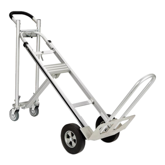
H-4124
3-IN-1 HAND TRUCK WITH
SOLID RUBBER WHEELS
TOOls NEEDED
10mm Wrench
14mm Wrench
Hammer
Pliers
WARNING! Do not use power tools.
PAGE 1 OF 4
1-800-295-5510
uline.com
AssEMBlY
AttAcH HAndlE
1. Slide handle onto the top rails of frame. Align holes
in handle and frame. Insert (2) 10mm bolts through
frame and handle and secure with locknuts.
(See Figure 1)
Figure 1
AttAcH nOSE PlAtE, FOldInG nOSE
ExtEnSIOn And AxlE SuPPOrtS
1. Position frame reinforcements against bottom of
frame rail. Slide nose plate into channel on frame
reinforcements. Keep bolt holes aligned.
(See Figure 2)
2. Align axle supports with outside rail of frame. Make
sure supports are positioned as shown.
(See Figure 2)
3. Insert (4) 14mm bolts through the axle supports,
Figure 2
frame, frame reinforcements and nose plate.
Pour le français, consulter les pages 3-4.
NOTE: Align top two bolt holes on axle support.
0414 IH-4124
Advertisement
Table of Contents

Related Manuals for U-Line H-4124


Summary of Contents for U-Line H-4124
- Page 1 Pour le français, consulter les pages 3-4. H-4124 1-800-295-5510 uline.com 3-IN-1 HAND TRUCK WITH SOLID RUBBER WHEELS TOOls NEEDED 10mm Wrench 14mm Wrench Hammer Pliers WARNING! Do not use power tools. AssEMBlY AttAcH HAndlE 1. Slide handle onto the top rails of frame. Align holes in handle and frame.
- Page 2 AssEMBlY cONTINuED 4. Slide the folding nose extension brackets over the Figure 3A 14mm bolts. (See Figure 3A) NOTE: The bolt holes on bracket are NOT centered. Make sure the bolt holes are closest to the back of truck before securing. (see Figure 3B) 5.
- Page 3 π H-4124 1-800-295-5510 uline.ca DIABLE 3-EN-1 AVEC ROUES À BANDAGE CAOUTCHOUC PLEIN OuTIls REQuIs clé 10 mm clé 14 mm Marteau Pinces ARRÊT AVERTIssEMENT! N'utilisez pas d'outils électriques. MONTAGE FIxAtIOn dE lA POIGnéE 1. Glissez la poignée sur les rails supérieurs du cadre.
- Page 4 MONTAGE suITE 4. Glissez les supports de la rallonge de bavette Figure 3A repliable sur les boulons de 14 mm. (Voir Figure 3A) REMARQuE : les trous de boulon du support ne sont PAs centrés. Assurez-vous que les trous de boulon sont positionnés plus près de l'arrière du diable avant de serrer le tout.
Need help?
Do you have a question about the H-4124 and is the answer not in the manual?
Questions and answers