
Related Manuals for Keysight N8481S


Summary of Contents for Keysight N8481S
- Page 1 Thermocouple Power Sensors N8481S - DC to 18 GHz N8487S - DC to 50 GHz Operating and Service Guide...
- Page 2 Conformity. understood and met. where in the EULA. Keysight shall be under no obligation to update, revise or otherwise modify the Software. With WARNING respect to any technical data as defined by FAR 2.101, pursuant to FAR...
-
Page 3: Safety Considerations
Return the product to a Keysight Sales and Service Office for service and repair to ensure the safety features are maintained. CLEAN WITH SLIGHTLY DAMPENED CLOTH... - Page 4 – Use the instrument with the cables provided. CAUTION – Repair or service that is not covered in this manual should only be performed by qualified personnels. Keysight N8481/7S Operating and Service Guide...
-
Page 5: Regulatory Markings
The UKCA (UK Conformity Assessed) marking is a UK product marking that is used for goods being placed on the market in Great Britain (England, Wales, and Scotland) Sales and Technical Support To contact Keysight for sales and technical support, refer to the support links on the following Keysight websites: –... - Page 6 THIS PAGE HAS BEEN INTENTIONALLY LEFT BLANK. Keysight N8481/7S Operating and Service Guide...
-
Page 7: Table Of Contents
...........39 Keysight N8481/7S Operating and Service Guide... - Page 8 ......44 Packaging the N8481/7S for shipment ..... . 44 Keysight N8481/7S Operating and Service Guide...
- Page 9 Serial number ....... .43 Keysight N8481/7S Operating and Service Guide...
- Page 10 THIS PAGE HAS BEEN INTENTIONALLY LEFT BLANK. Keysight N8481/7S Operating and Service Guide...
- Page 11 Power Table ....... . .35 Keysight N8481/7S Operating and Service Guide...
- Page 12 THIS PAGE HAS BEEN INTENTIONALLY LEFT BLANK. Keysight N8481/7S Operating and Service Guide...
- Page 13 Keysight N8481/7S Power Sensors Operating and Service Guide Introduction General Information Overview of the N8481/7S Power Sensors This chapter contains information about initial inspection and overview of the Keysight N8481/7S power sensors.
-
Page 14: Introduction
– Procedures for checking electrical performance are given under “Operator’s check” on page 40. 2 If the contents are damaged or defective, contact your nearest Keysight Technologies Service and Support Office. Refer to “Sales and Technical Support” on page 5 of this manual. Keysight Technologies will arrange for repair or replacement of the damaged or defective equipment. -
Page 15: Shipment Content List
The diode module is static sensitive and can be damaged or the calibration CAUTION can be altered. Do not rotate the body of the N8481/7S power sensors when connecting to CAUTION the instrument/DUT, or internal damage may result. Keysight N8481/7S Operating and Service Guide... - Page 16 – Ground yourself before you clean, inspect, or make a connection to the N8481/7S. You can, for example, grasp the grounded outer shell of the analyzer test port or cable connector briefly. – Avoid touching the exposed connector pins. Keysight N8481/7S Operating and Service Guide...
-
Page 17: Recommended Calibration Interval
Introduction Recommended calibration interval Keysight Technologies recommends a one year calibration cycle for the N8481/7S power sensors. Temperature sensitivity The sensitivity of the power sensor is influenced by ambient temperature. The sensor should be recalibrated at each change in temperature to obtain the most accurate results. - Page 18 RF connector type, wrench size, and torque values Table 1-2 Keysight Torque Wrench Model RF connector Torque value Part Number N8481S Type-N (male) 8710-1766 136 N-cm (12 in-lb) N8487S 2.4 mm (male) 8710-1765 90 N-cm (8 in-lb) Keysight N8481/7S Operating and Service Guide...
-
Page 19: Overview Of The N8481/7S Power Sensors
In this approach, the unknown RF power is substituted by traceable DC power. These power sensors are based on Keysight dual thermopiles power detectors constructed on a single chip which is either TC150 or TC152. There are two sides of thermopiles in the detectors that are constructed to closely match the power cancellation and thermal stability. -
Page 20: Figure 1-1 N8481/7S Measurement Setup Diagram
The Balance Thermoelectric Power Standard mainly consists of Thermocouple IC that is built on Thin Film circuit in a cartridge assembly that serves as a transition from coaxial to CPW transition in a Keysight N8481/7S Operating and Service Guide... -
Page 21: N8481S Power Sensor
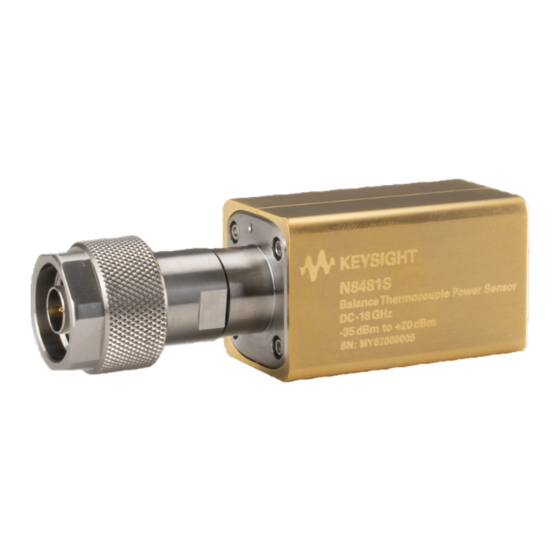
N8481S power sensor The N8485A power sensor is fitted with Type-N (m) connector as standard and has an operating frequency range of DC to 18 GHz. See Figure 1-2. N8481S power sensor Figure 1-2 Keysight N8481/7S Operating and Service Guide... -
Page 22: N8487S Power Sensor
N8487S power sensor The N8487S power sensor is fitted with 2.4 mm (m) connector as standard and has an operating frequency range of DC to 50 GHz. See Figure 1-3. Figure 1-3 N8487S power sensor Keysight N8481/7S Operating and Service Guide... - Page 23 Introduction THIS PAGE HAS BEEN INTENTIONALLY LEFT BLANK. Keysight N8481/7S Operating and Service Guide...
- Page 24 Introduction Keysight N8481/7S Operating and Service Guide...
- Page 25 Keysight N8481/7S Power Sensors Operating and Service Guide Specifications and Characteristics Environmental Specifications Physical Specifications This chapter provides you the environmental and physical specifications of the N8481/7S power sensors.
-
Page 26: Specifications And Characteristics
Keysight N8481/7S power sensors are designed to fully comply with Keysight Technologies’ product operating environmental specifications as shown in the table below. Samples of this product have been type tested in accordance with the Keysight NOTE Environmental Test Manual and verified to be robust against the Environmental stresses of Storage, Transportation and End-use;... -
Page 27: Physical Specifications
Specifications and Characteristics Physical Specifications Table 2-2 lists the physical specifications of the Keysight N8481/7S power sensors. N8481/7S Physical Specifications Table 2-2 Model Weight Dimensions N8481S 120 grams 87 mm L x 26 mm W x 28 mm H (approx) -
Page 28: Figure 2-2 N8487S Power Sensor
Specifications and Characteristics Figure 2-2 N8487S Power Sensor For the detailed characteristics and specifications of the N8481/7S Power NOTE Sensors, refer to the Technical Overview document at www.literature.cdn.keysight.com/litweb/pdf/5989-9333EN.pdf Keysight N8481/7S Operating and Service Guide... - Page 29 Keysight N8481/7S Power Sensors Operating and Service Guide Service Cleaning Performance Test Adjustments Troubleshooting Repair This chapter contains information about principle of operations, troubleshooting, and repair of the Keysight N8481/7S power sensors.
-
Page 30: Service
If the swab is too big, use a round wooden toothpick wrapped in a lint free cloth dipped in isopropyl or ethyl alcohol. Keysight N8481/7S Operating and Service Guide... -
Page 31: Performance Test
2 Set the start frequency of the network analyzer to 9 kHz and the stop frequency to 10 MHz (for the Option 200). 3 Calibrate the network analyzer using the 85054B calibration kit. Perform calibration for the open, short, and load circuits of the network analyzer. Keysight N8481/7S Operating and Service Guide... - Page 32 Turn on Correction on the network analyzer to perform the VSWR measurement. 5 Compare the measured results to the specifications in the datasheet. If the verification fails, refer to “Adjustments” on page 37. Keysight N8481/7S Operating and Service Guide...
-
Page 33: Calibration Factor Test
Source measure unit 6.5-digit B2912B Digital multimeter 8.5-digit 3458A Procedure 1 Connect the standard sensor (N8481A/N8485A/N8487A/N8488A) to the power meter’s channel A and the incident sensor (N8481A/N8485A/N8487A/ N8488A) to the power meter’s channel B. Keysight N8481/7S Operating and Service Guide... -
Page 34: Figure 3-1 Equipment Setup For Low Power Verification
A (standard sensor) measures 0 dBm. 6 Record the signal generator power and power meter channel B (incident sensor 1) power in the table below. 7 Repeat steps 4 to 6 for other frequencies. Keysight N8481/7S Operating and Service Guide... - Page 35 12 Set the amplitude of the signal generator to the value recorded in the table above. 13 Adjust the SMU voltage until the DUT is balanced. 14 Record the power meter channel B (incident sensor 2) power in the table above. Keysight N8481/7S Operating and Service Guide...
- Page 36 Where: P and P are power in Watts. INC2 INC1 Γ , Γ and Γ are the complex reflection coefficient of the DUT, standard sensor and equivalent output port match of the power splitter respectively. Keysight N8481/7S Operating and Service Guide...
-
Page 37: Adjustments
Performance verification must be completed after any repairs that may have altered the characteristics of the N8481/7S. The N8481/7S is required to be returned to Keysight for adjustments. To arrange this, contact the Keysight Service Center. Refer to “Sales and... -
Page 38: Troubleshooting
Electrostatic discharge will render the power sensor inoperative. Do not, under any circumstances, open the power sensor unless you and the power sensor are in a static free environment. Keysight N8481/7S Operating and Service Guide... -
Page 39: Repair
The N8481/7S power sensors does not have serviceable parts and should only be repaired by service-trained personnel. Should it become necessary to return the N8481/7S for repair or service, contact your nearest Keysight Service Center. Keysight N8481/7S Operating and Service Guide... - Page 40 Service THIS PAGE HAS BEEN INTENTIONALLY LEFT BLANK. Keysight N8481/7S Operating and Service Guide...
- Page 41 Keysight N8481/7S Power Sensors Operating and Service Guide Contacting Keysight Introduction Returning the N8481/7S for Service This chapter explains the appropriate actions to take if you have a problem with your N8481/7S.
-
Page 42: Contacting Keysight
Introduction This section provides the information on what to do if you encounter problems with your N8481/7S. If you wish to contact Keysight to enquire about the N8481/7S, from service problems to ordering information, refer to “Sales and Technical Support”... -
Page 43: Recommended Calibration Interval
– The suffix indicates an alphanumeric code which is used to ensure unique identification of each product throughout Keysight. SERIAL NUMBER SER MY12345678 Keysight MADE IN MALAYSIA Serial number Figure 4-1 Recommended calibration interval Keysight recommends a one-year calibration cycle for the N8481/7S. Keysight N8481/7S Operating and Service Guide... -
Page 44: Returning The N8481/7S For Service
Use the information in this section if you need to return your N8481/7S to Keysight. Packaging the N8481/7S for shipment Use the following procedure to package the N8481/7S for shipment to Keysight for servicing: – Be as specific as possible about the nature of the problem. Send a copy of any information on the performance of the N8481/7S. - Page 45 This information is subject to change without notice. Always refer to the Keysight website for the latest revision. © Keysight Technologies 2022 Edition 1, November 8, 2022 Printed in Malaysia N8481- 90013 www.keysight.com...
Need help?
Do you have a question about the N8481S and is the answer not in the manual?
Questions and answers