Advertisement
Advertisement

Related Manuals for Keysight 1147B


Summary of Contents for Keysight 1147B
- Page 1 Keysight 1147B 50 MHz Current Probe User’s Guide...
- Page 2 A WARNING notice denotes a hazard. It calls purpose. Keysight shall not be liable for errors or for attention to an operating procedure, practice, incidental or consequential damages in connection...
-
Page 3: Table Of Contents
Contents Introduction / Safety / Description of Parts / Using the Probe / Performance Verification for 1147B Probe / Characteristics and Specifications / Product Markings and Labels / Service Strategy /... -
Page 5: Introduction
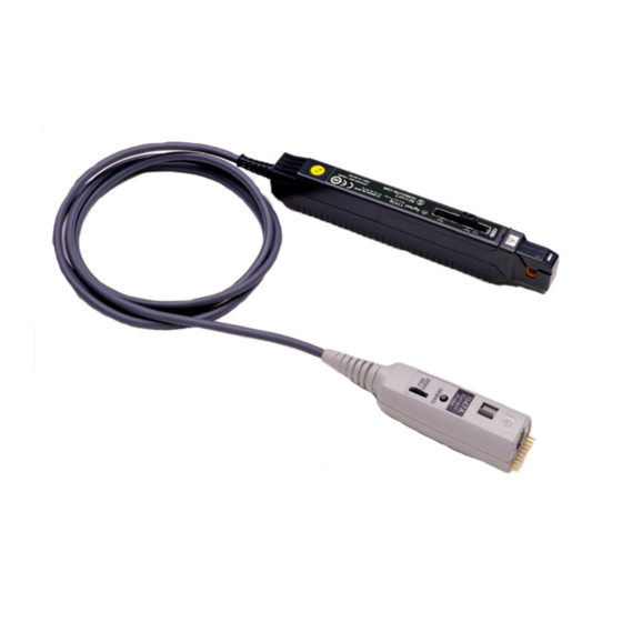
Introduction Introduction The 1147B is a wide-band, DC to 50 MHz, active current probe. The probe features low noise and low circuit insertion loss. The intelligent interface makes the probe ideal for use with the InfiniiVision and Infiniium products using the AutoProbe interface. -
Page 6: Safety
To avoid short circuits and accidents that could result in injury or WARNING death, use the 1147B only with power lines carrying 300V or less. When conductors being measured carry in excess of the safe WARNING... - Page 7 Safety This instrument is only made for use with the Infiniium. Do not WARNING plug the probe into any interface other than the AutoProbe interface, of which Infiniium has a protective earthing with double-insulation construction. Take the following precautions to ensure that the Infiniium does WARNING not form a bridge between the probe and any hazardous live part: - Isolate the AutoProbe interface to which the probe is...
- Page 8 Safety If excess current is input, generated heat activates a built-in WARNING safety function that blocks normal output. If this happens, remove the input immediately (unclamp the sensor from the conductor being measured or reduce the input current to zero). Wait until the sensor has had sufficient time to cool before resuming operation.
- Page 9 CAUTION sure that the unit was not damaged due to poor storage or transport conditions. If damage is found, contact your dealer or Keysight representative. This unit is not constructed to be waterproof or dustproof, so do CAUTION not use it in a very dusty environment or in one where it will get...
- Page 10 Safety The sensor head is a precision assembly including a molded CAUTION component, a ferrite core, and a Hall effect element. It may be damaged if subjected to sudden changes in ambient temperature, or mechanical strain or shock, and therefore great care should be exercised in handling it.
-
Page 11: Description Of Parts
Description of Parts Description of Parts Figure 2 Probe Parts Identification Opening Lever Operating lever for opening the sensor head. Always use this lever to open the sensor head. Sensor Head This clamps the conductor being measured, and carries out the actual current measurement. - Page 12 Description of Parts Zero Adjustment Dial (ZERO ADJ) Use the zero adjustment dial to correct for the effect of a voltage offset or temperature drift on the unit. The probe should be always be zeroed after demagnetization. Refer to “Demagnetization and Zero Adjustment”...
-
Page 13: Using The Probe
Figure 3 Connecting the Probe to the Oscilloscope When the probe is connected to a scope channel, the AutoProbe interface N OTE recognizes the probe as an 1147B and automatically sets the channel to Ω input resistance with DC input coupling. - Page 14 Using the Probe Perform the steps in “Demagnetization and Zero Adjustment" on page Using the probe’s opening lever, clamp the sensor head around the conductor to be measured as shown in Figure 4 on page Always use the opening lever when opening the probe’s sensor CAUTION head.
- Page 15 Using the Probe Figure 5 Clamp Onto the Low-Voltage Side of Circuit At some frequencies, some sound may be produced by resonance, this has N OTE no effect on measurements. Measurement accuracy is affected by the position of the conductor being N OTE measured within the clamp aperture.
- Page 16 Using the Probe Demagnetization and Zero Adjustment Allow both the Infiniium oscilloscope and the probe to warm up for at least 30 minutes before making these adjustments. Ensure that the channel offset is set to 0V on the oscilloscope channel to which the probe is connected. Ensure that the probe sensor is NOT clamped around any conductors.
-
Page 17: Performance Verification For 1147B Probe
Use the following procedure to test the warranted Accuracy specifications (as listed on page 21) for the 1147B probe. The recommended test interval to warrant performance of this probe is once a year. However, you can also test the probe’s performance as and when required using the recommended test equipment and by following the procedure documented in this chapter. - Page 18 Figure 7 on page 19 as per the following substeps. a Clamp the 1147B probe around the test cable <1> and lock the sensor head of the probe. b Press the DEMAG button on the probe. c Set the digital multimeter (DMM <1>) to A mode.
- Page 19 Performance Verification for 1147B Probe Figure 7 Setting up AC Current Generator Set the DMM <2> to V mode. As displayed in Figure 8 on page 20, connect a BNC cable to the: a N1022B adapter’s output using the NMD 3.5mm (M) to 3.5mm (F) adapter and 3.5mm (M) to BNC (F) adapter.
- Page 20 Measure the current and record V output of the probe as displayed on the DMM <2>. Calculate gain as follows: Gain = Gain should be between 0.99 and 1.01 (+/-1% gain accuracy). Remove the test cable and AC current generator from the 1147B probe.
-
Page 21: Characteristics And Specifications
Characteristics and Specifications Characteristics and Specifications Table 2 Measurement Characteristics Item Characteristic Probe Bandwidth DC to 50 MHz (–3 dB) Accuracy (Probe Only) ±1% of reading ±1mV (DC or 45 Hz to 66 Hz) Risetime ¤ 7ns Maximum current With InfiniiVision 3000X/T, 5000/6000/7000 Series: 15A peak(DC+AC peak), 15A , 10A continuous... - Page 22 Characteristics and Specifications Table 3 Power Supply Characteristics Item Characteristics DC supply voltage requirements ±12Vdc ±1V Probe power consumption Increases with measured current. 3 VA when measuring Table 4 Mechanical Characteristics Item Characteristics Maximum cable diameter 5 mm (0.2 inch) Sensor cable length 1.5 m (59 inches) Power cable length...
- Page 23 Characteristics and Specifications Figure 9 Frequency Characteristic Figure 10 Derating According to Frequency Figure 11 Insertion Impedance...
-
Page 24: Product Markings And Labels
Product Markings and Labels Product Markings and Labels Table 6 Instrument Markings Marking Description Indicates the maximum circuit voltage and product compliance. This symbol indicates the Environmental Protection Use Period (EPUP) for the product’s toxic substances for the China RoHS requirements. The CE symbol indicates the European Community. -
Page 25: Service Strategy
Service Strategy Service Strategy For repair and calibration testing, return the 1147B probe to a Keysight Service Center. If the probe is under warranty, normal warranty services apply. If the probe is not under warranty, repair costs will be applied. - Page 26 Service Strategy...
- Page 27 Index Index AC accuracy IEC 61010-1 Safety Standards accuracy impedance, insertion AutoProbe insertion impedance inspection instrument markings built-in safety circuit ISM1-A cable diameter labels CE symbol characteristics and specifications China RoHS requirements maximum altitude cleaning maximum cable diameter coarse adjustment trimmer maximum circuit voltage current direction indicator maximum current...
- Page 28 Index risetime safety warnings SELV-E sensitivity sensor cable length sensor head service sound storage temperature range temperature coefficient temperature range using vibration weight ZERO ADJ zero adjustment dial...
Need help?
Do you have a question about the 1147B and is the answer not in the manual?
Questions and answers