Table of Contents
Advertisement
Quick Links
Advertisement
Table of Contents

Related Manuals for Keysight E4412A


Summary of Contents for Keysight E4412A
- Page 1 Keysight E4412A and E4413A Power Sensors Operating and Service Guide...
- Page 2 Do not proceed beyond a WARNING acquires no greater than Limited Rights as defined in FAR 27.401 or DFAR notice until the indicated conditions are 227.7103-5 (c), as applicable in any fully understood and met. technical data. Keysight E4412A and E4413A Operating and Service Guide...
-
Page 3: Certification
Keysight shall not be liable for errors or for incidental or consequential damages in connection with the furnishing, use, or performance of this document or any information contained herein. -
Page 4: Limitation Of Warranty
Buyer. Keysight does not warrant the Buyer’s circuitry or malfunctions of Keysight products that result from the Buyer’s circuitry. In addition, Keysight does not warrant any damage that occurs as a result of the Buyer’s circuit or any defects that result from Buyer-supplied products. -
Page 5: Safety Summary
Failure to comply with these precautions or with specific warnings elsewhere in this manual violates safety standards of design, manufacture, and intended use of the instrument. Keysight Technologies, Inc. assumes no liability for the customer’s failure to comply with these requirements. -
Page 6: Safety Symbols
On (Supply). Off (Supply). Equipment protected throughout by DOUBLE INSULATION or REINFORCED Caution, risk of electric shock. INSULATION. Caution, hot surface. In position of bi-stable push control. Out position of bi-stable push control. Keysight E4412A and E4413A Operating and Service Guide... -
Page 7: Environmental Conditions
Environmental Conditions The E4412A and E4413A is designed for indoor use and in an area with low condensation. The table below shows the general environmental requirements for this instrument. Environmental condition Requirement Operating condition – 0 to 55 ºC Temperature Storage condition –... -
Page 8: Regulatory Markings
This ISM device complies with the equipment. The affixed product label Canadian ICES-001. indicates that you must not discard Cet appareil ISM est conforme à la this electrical/electronic product in norme NMB-001 du Canada. domestic household waste. Keysight E4412A and E4413A Operating and Service Guide... -
Page 9: General Safety Information
Failure to comply with these precautions or with specific warnings elsewhere in this manual violates safety standards of design, manufacture, and intended use of the instrument. Keysight Technologies assumes no liability for the customer’s failure to comply with these requirements. -
Page 10: Waste Electrical And Electronic Equipment (Weee) Directivel
To return this unwanted instrument, contact your nearest Keysight Service Center, or visit http://about.keysight.com/en/companyinfo/environment/takeback.shtml for more information. Sales and Technical Support To contact Keysight for sales and technical support, refer to the support links on the following Keysight websites: – www.keysight.com/find/powersensors (product-specific information and support, software and documentation updates) –... -
Page 11: Table Of Contents
......... .27 Keysight E4412A and E4413A Operating and Service Guide... - Page 12 ..........42 Keysight E4412A and E4413A Operating and Service Guide...
- Page 13 ....35 Figure 1-9 Removing power sensor shell ....41 Keysight E4412A and E4413A Operating and Service Guide...
- Page 14 THIS PAGE HAS BEEN INTENTIONALLY LEFT BLANK. Keysight E4412A and E4413A Operating and Service Guide...
- Page 15 Table 1-3 Replaceable parts ......36 Keysight E4412A and E4413A Operating and Service Guide...
- Page 16 THIS PAGE HAS BEEN INTENTIONALLY LEFT BLANK. Keysight E4412A and E4413A Operating and Service Guide...
- Page 17 Keysight E4412A and E4413A Power Sensors Operating and Service Guide Operation and Service Guide General Information Performance Test Replaceable Parts Service Adjustments This chapter contains information about initial inspection, performance tests, specifications, operations, troubleshooting and service of the Keysight E4412A and E4413A power sensors.
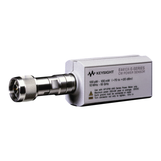
- Page 18 Operation and Service Guide Figure 1-1 E4412A and E4413A power sensors (formerly ECP-E18A and EXCP-E26A, respectively) Keysight E4412A and E4413A Operating and Service Guide...
-
Page 19: Operation And Service Guide
The four numbers of the prefix are a code identifying the date of the last major design change incorporated in your Keysight Technologies product. The four-digit suffix is a sequential number and, coupled with the prefix, provides a unique identification for each unit produced. -
Page 20: Description
CW microwave power levels in a wide dynamic range from -70 dBm to +20 dBm (100 pW to 100 mW). The E4412A measures at frequencies from 10 MHz to 18.0 GHz. The E4413A measures at frequencies from 50 MHz to 26.5 GHz. -
Page 21: Installation
Keysight Technologies representative. Interconnections Connect one end of the 11730A sensor cable to the E4412A or E4413A power sensor and connect the other end of the cable to the power meter’s channel input. Allow a few seconds for the power meter to download the power sensor’s calibration table before making a measurement. -
Page 22: Storage And Shipment
Containers and materials identical to those used in factory packaging are available through Keysight Technologies offices. If the instrument is being returned to Keysight Technologies for servicing, attach a tag indicating the type of service required, return address, model number, and serial number. -
Page 23: Power Meter Calibrations
– The adapter supplied with a new sensor typically has a loss of < 0.1%. Adapter loss could potentially contribute to absolute power measurement accuracy and needs to be considered. Keysight E4412A and E4413A Operating and Service Guide... -
Page 24: Adapter Test Procedure
S12 and S21 0.999235 dB (lin mag) 0.999205 dB (lin mag) <0.1% <0.1% Open, Short, Load, Sliding load Port 1 Open, Short, Load, Sliding load Port 2 Figure 1-3 System calibration setup Keysight E4412A and E4413A Operating and Service Guide... - Page 25 Cal Kit (Open, Short, and Load). 8 When the wizard prompts for a through adapter connection, attach the adapter-under-test as the unknown adapter. 9 The firmware will estimate the delay, which should be approximately 0.11 ns. Keysight E4412A and E4413A Operating and Service Guide...
-
Page 26: Operating Instructions
Operating instructions The E4412A and E4413A power sensors are compatible ONLY with the newer E44XX-Series power meters. They are NOT compatible with the earlier 430-Series, E1416A, or 70100A power meters. To operate the power sensor, refer to the operating instructions in the Keysight E44XX-Series Power Meter User’s... -
Page 27: Performance Test
2 Set the start frequency of the network analyzer to 10 MHz or 50 MHz and the stop frequency to 18 GHz for E4412A or 26.5 GHz for E4413A or 33 GHz for H33 option. For the calibration, power must be 0 dBm and 17 dBm. - Page 28 CPLR ARM RCVR A IN CPLR THRU SOURCE Power amplifier RCVR R1 IN Attenuator Input port E4412A and E4413A Coupled port Transmitted port Figure 1-5 Equipment setup for high power S11 verification Keysight E4412A and E4413A Operating and Service Guide...
- Page 29 11 Ensure that the "C 1-Port" and "SrcPwrCal" status indicators are displayed on the network analyzer. 12 Connect the E4412A and E4413A (device-under-test) to the test port of the network analyzer. 13 Compare the measured results to the specifications in the data sheet. If the verification fails, refer to “Adjustments”...
-
Page 30: Power Linearity Performance Verification
Power linearity performance verification The power linearity performance verification measures the relative linearity error of the E-Series E4412A and E4413A power sensor. All measurements are performed at 50 MHz. The reference power level for the linearity measurement is 0 dBm. - Page 31 Record the values as P at 0 dBm and P at 0 dBm. Do not exceed the maximum input power (27 dBm) of the power splitter to CAUTION avoid damage to the power splitter. Keysight E4412A and E4413A Operating and Service Guide...
-
Page 32: Zero Set Performance Verification
Zero set is the difference between the power levels indicated by the DUT, after executing zeroing and the true zero power. Ideally, this difference should be zero. This performance verification requires the E4416/7A power meter. Keysight E4412A and E4413A Operating and Service Guide... - Page 33 Operation and Service Guide Procedure 1 Connect the DUT (E-Series E4412A or E4413A power sensor) to the power meter as shown in Figure 1-7. Figure 1-7 Zero set performance verification equipment setup 2 Warm up the DUT for approximately 30 minutes.
-
Page 34: Replaceable Parts
Table 6 is a list of replaceable parts. Figure 1-8 is the illustrated parts breakdown (IPB) that identifies all of the replaceable parts. To order a part, quote the Keysight Technologies part number, specify the quantity required, and address the order to the nearest Keysight Technologies office. - Page 35 Operation and Service Guide Figure 1-8 Illustrated parts break down Keysight E4412A and E4413A Operating and Service Guide...
- Page 36 SHELL PLASTIC 08481-20011 CHASSIS 08481-20011 CHASSIS 08481-00002 SHIELD 08481-00002 SHIELD MP26 E4412-80002 LABEL, ID E4412A MP26 E4413-80002 LABEL, ID E4413A MP27 7121-7389 LABEL, POWER SENSOR MP30 7121-7388 LABEL, CAL/ESD MP31 00346-80011 LABEL, CAUTION Keysight E4412A and E4413A Operating and Service Guide...
-
Page 37: Service
EEPROM. This configures the power meter to operate over the +20 dBm power range with that particular sensor’s unique correction data applied. Keysight E4412A and E4413A Operating and Service Guide... -
Page 38: Troubleshooting
Subjecting a power sensor module above its maximum allowable power rating is considered a misuse or self-abuse and is excluded from Keysight Technologies’ standard warranty coverage. Refer to the Power Sensor Electrical Overstress (EOS) Failure Verification Guideline at https://literature.cdn.keysight.com/litweb/pdf/5992-4039EN.pdf. -
Page 39: Connector Maintenance
– Do not overtighten connectors and do not allow them to become loose — use a torque wrench. – Do not mate dissimilar families, for example APC-3.5 and SMA. – Avoid temperature extremes. Keysight E4412A and E4413A Operating and Service Guide... -
Page 40: Cleaning
Clean the connector face using a cotton swab dipped in isopropyl alcohol. If the swab is too big use a round wooden toothpick wrapped in a lint free cotton cloth dipped in isopropyl alcohol. Refer to Keysight Application Note 326, Principals of Microwave Connector Care (5954-1566) or Microwave Connector Care (08510-90064) for proper cleaning methods. -
Page 41: Disassembly Procedure
2 Pry alternately at both sides of the connector J1 until the plastic shells are apart. Remove the shells and the magnetic shields. Reassembly procedure 1 Replace the magnetic shields and the plastic shells as shown in Figure 1-9. Snap the plastic shells together. Keysight E4412A and E4413A Operating and Service Guide... -
Page 42: Adjustments
Performance verification must be completed after any repairs that may have altered the characteristics of the E-Series E4412A and E4413A power sensors. The E-Series E4412A and E4413A power sensors can be returned to Keysight for adjustments. - Page 43 This information is subject to change without notice. Always refer to the Keysight website for the latest revision. © Keysight Technologies 1999 - 2022 Edition 11, February 24, 2022 Printed in Malaysia E4412-90013 www.keysight.com...
Need help?
Do you have a question about the E4412A and is the answer not in the manual?
Questions and answers