
Subscribe to Our Youtube Channel
Related Manuals for Keysight U2040 X Series


Summary of Contents for Keysight U2040 X Series
- Page 1 Keysight U2040 X-Series Wide Dynamic Range Power Sensors Wide dynamic range power sensors for any modulated signals User’s Guide...
- Page 2 Dec- set forth specifically in writing else- understood and met. laration of Conformity. where in the EULA. Keysight shall be under no obligation to update, revise or WARNING otherwise modify the Software. With respect to any technical data as defined by FAR 2.101, pursuant to FAR...
-
Page 3: Environmental Conditions
Altitude Storage condition – Up to 15420 m (50000 ft) Regulatory Information The U2040 X-Series complies with the following Electromagnetic Compatibility (EMC) compliances: – IEC 61326-1/EN 61326-1 – Canada: ICES/NMB-001 – Australia/New Zealand: AS/NZS CISPR11 Keysight U2040 X-Series User’s Guide... -
Page 4: Regulatory Markings
This symbol is a South Korean Class A EMC Declaration. This is a Class A instrument suitable for professional use and in electromagnetic environment MSIP-REM-Kst- outside of the home. XXXXXXXXX Keysight U2040 X-Series User’s Guide... -
Page 5: Waste Electrical And Electronic Equipment (Weee) Directive 2002/96/ Ec
“Monitoring and Control Instrument” product. The affixed product label is as shown below. Do not dispose in domestic household waste. To return this unwanted instrument, contact your nearest Keysight Service Center, or visit http://about.keysight.com/en/companyinfo/environment/takeback.shtml for more information. -
Page 6: Sales And Technical Support
Sales and Technical Support To contact Keysight for sales and technical support, refer to the support links on the following Keysight websites: – www.keysight.com/find/widedynamicsensor (product-specific information and support, software and documentation updates) – www.keysight.com/find/assist (worldwide contact information for repair and service) -
Page 7: Table Of Contents
......... 42 General Operating Information Using the U2040 X-Series with the Keysight BenchVue ... . 44 Quick start example to perform an average power measurement . - Page 8 ........88 Limit Checking Application Example ......89 Keysight U2040 X-Series User’s Guide...
- Page 9 ... . 24 Figure 1-8 Add a LAN instrument in Keysight Connection Expert via host name ....... . 25...
- Page 10 System error ....... . .80 Keysight U2040 X-Series User’s Guide...
- Page 11 ....... . 68 Table A-1 Range of values for limits ..... . 89 Keysight U2040 X-Series User’s Guide...
- Page 12 THIS PAGE HAS BEEN INTENTIONALLY LEFT BLANK. Keysight U2040 X-Series User’s Guide...
- Page 13 Keysight U2040 X-Series Wide Dynamic Range Power Sensors User’s Guide Getting Started Overview Theory of Operation Standard shipped items Hardware Installation and Configuration Connect the U2041XA/42XA/43XA/44XA sensor Connect the U2049XA sensor Mount the U2049XA Option TVA Mounting dimensions Mounting procedure...
-
Page 14: Getting Started
Power over Ethernet (PoE)/LAN connectivity. The PoE connectivity is compliant to the IEEE 3 W, 802.3af or 802.3at Type 1 standard. The typical LAN port on your PC or Keysight instruments is not able to power up the NOTE U2049XA. The U2049XA must be connected to a PoE port, which supplies the DC power required to power up the U2049XA and to transfer data. -
Page 15: Figure 1-1 U2041/42/43/44Xa Sensor
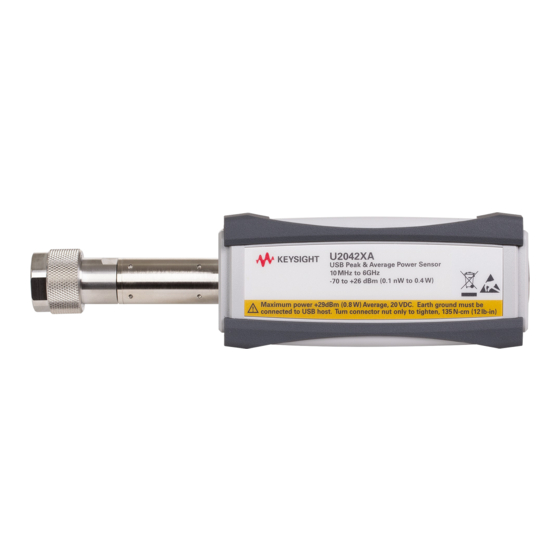
RF/microwave signals USB cable External trigger ports USB port LED indicator Indicates the U2041/42/43/44XA state. Refer to “LED Indicator Sequence During Power-Up for the U2041XA/ 42XA/43XA/44XA Sensor” on page for more information. Figure 1-1 U2041/42/43/44XA sensor Keysight U2040 X-Series User’s Guide... -
Page 16: Figure 1-2 U2049Xa Sensor
): Link activity indicator. state. Blinks when a valid link activity is detected. LED indicators Indicate the U2049XA state. Refer to “LED Indicator Sequences for the U2049XA Sensor” on page more information. Figure 1-2 U2049XA sensor Keysight U2040 X-Series User’s Guide... -
Page 17: Theory Of Operation
“aperture” to calculate this averaging. This aperture is selectable from 20 μs to 200 ms with 100 ns resolution and provides a powerful mechanism for precisely tuning the instrument to the signal being measured. In addition to allow the Keysight U2040 X-Series User’s Guide... - Page 18 U2040 X-Series sensor to be paired with either conventional USB or LAN based interface. On top of that, the U2040 X-Series sensor is also designed to be thermal vacuum compliant (TVAC) by controlling the outgas property of the components being used. Keysight U2040 X-Series User’s Guide...
-
Page 19: Initial Inspection
If there is any mechanical damage, notify the nearest Keysight Sales and Service Office. Keep the damaged shipping materials (if any) for inspection by the carrier and a Keysight representative. - Page 20 (for Option TVA) Certificate of calibration Shielded LAN cable 5 ft (1.5 m), Thermal vacuum (TVAC) LAN cable 5 ft default cable length (1.5 m), default cable length (for Option 100) (for Option TVA) Certificate of calibration Keysight U2040 X-Series User’s Guide...
-
Page 21: Hardware Installation And Configuration
Prior to using the U2040 X-Series, ensure that the following minimum requirements are met: – PC with USB and LAN host capability – Keysight IO Libraries Suite 17.0 or higher installed – Keysight BenchVue installed Connect the U2041XA/42XA/43XA/44XA sensor 1 Connect the power sensor to the PC. The sensor driver is detected and installed automatically. -
Page 22: Figure 1-5 Auto-Locate A Usb Instrument In Keysight Connection Expert
3 Click Interactive IO to verify the sensor is connected. 4 When the sensor is connected, go to Chapter 2, "Using the U2040 X-Series with the Keysight BenchVue" to launch the BenchVue Power Meter application, or proceed to operate the sensor via remote programming. -
Page 23: Connect The U2049Xa Sensor
– Static IP (Manual mode) The default LAN operating mode of the U2049XA is Dynamic IP. Dynamic IP and Auto IP are enabled on the U2049XA shipped from Keysight. This allows the U2049XA to automatically obtain an address on the network. -
Page 24: Figure 1-7 Set Automatic Lan Settings On The Pc
Figure 1-7 Set automatic LAN settings on the PC 3 Go to Start > All Programs > IO Control ( ) to launch Keysight Connection Expert. 4 Select Add > LAN instrument. The Add a LAN device window is displayed. -
Page 25: Figure 1-8 Add A Lan Instrument In Keysight Connection Expert Via Host Name
Getting Started Figure 1-8 Add a LAN instrument in Keysight Connection Expert via host name 6 Select Allow *IDN Query and click Test This VISA Address to verify the U2049XA is connected. Once verified, click Accept. 7 Alternatively, you can auto-locate the U2049XA as shown in Figure 1-9. Click Rescan to start searching. -
Page 26: Figure 1-9 Auto-Locate A Lan Instrument In Keysight Connection Expert Via Dynamic Ip
8 Click Interactive IO to verify the U2049XA is connected. 9 When the U2049XA is connected, go to Chapter 2, "Using the U2040 X-Series with the Keysight BenchVue" to launch the BenchVue, or proceed to operate the U2049XA via remote programming. -
Page 27: Figure 1-10 Connect The U2049Xa Via Auto Ip
2 On your PC, set the LAN settings to the automatic configuration. Go to Start > Control Panel > Network and Internet > Network and Sharing Center > Local Area Connection > Properties and set the following properties. Keysight U2040 X-Series User’s Guide... - Page 28 4 Click Interactive IO to verify the U2049XA is connected. 5 When the U2049XA is connected, go to Chapter 2, "Using the U2040 X-Series with the Keysight BenchVue" to launch the BenchVue, or proceed to operate the U2049XA via remote programming.
-
Page 29: Figure 1-11 Connect The U2049Xa Via Static Ip
2 On your PC, set the LAN settings to the automatic configuration. Go to Start > Control Panel > Network and Internet > Network and Sharing Center > Local Area Connection > Properties and set the following properties. Keysight U2040 X-Series User’s Guide... - Page 30 Getting Started 3 Go to Start > All Programs > IO Control ( ) to launch Keysight Connection Expert. Click Start a Scan for connected instruments to auto-locate the sensor as shown in the figure below. 4 To enable static IP, click Interactive IO and send the following SCPI commands: –...
-
Page 31: Figure 1-12 Set Manual Lan Settings On The Pc
– For the new network settings to become effective, you must first power cycle the NOTE U2049XA. – The static IP addresses for the host PC and the U2049XA must be different from the IP address of the PoE injector to avoid conflict. Keysight U2040 X-Series User’s Guide... -
Page 32: Figure 1-13 Auto-Locate A Lan Instrument In Keysight Connection Expert Via Static Ip
(192.168.0.10) in the Add a LAN device (Add > LAN instrument) window. 8 When the U2049XA is connected, go to Chapter 2, "Using the U2040 X-Series with the Keysight BenchVue" to launch the BenchVue, or proceed to operate the U2049XA via remote programming. - Page 33 – interactive IO – familiarization with instrument capabilities – determining/changing instrument configuration 1 On the Keysight Connection Expert, click Web UI to launch the U2049XA web-based interface. The web-based interface can also be opened directly from a web browser by entering the NOTE U2049XA’s IP address or hostname in the ‘address’...
-
Page 34: Figure 1-14 U2049Xa Web-Based Interface (Welcome Page)
Getting Started Figure 1-14 U2049XA web-based interface (Welcome page) 2 Click View & Modify Configuration to access the LAN configuration settings. Keysight U2040 X-Series User’s Guide... -
Page 35: Figure 1-15 View And Modify Lan Configuration Settings
Getting Started Figure 1-15 View and modify LAN configuration settings 3 Click Modify Configuration to edit the LAN configuration settings. 4 Enter the default password “keysight”. Keysight U2040 X-Series User’s Guide... -
Page 36: Figure 1-16 Modify And Renew Lan Configuration Settings
Configuring the LAN remotely using SCPI commands You can send SCPI commands to automatically or manually configure the LAN settings for the U2049XA. Refer to the U2040 X-Series Programming Guide for details. Keysight U2040 X-Series User’s Guide... -
Page 37: Mount The U2049Xa Option Tva
The cooling plate consists of four mounting threaded holes and the minimum thread height of each hole is 6 mm. Mounting dimensions 53.06 mm 24.00 mm 136.00 mm 90.00 mm 40.00 mm 60.50 mm Figure 1-17 U2049XA Option TVA mounting dimensions Keysight U2040 X-Series User’s Guide... -
Page 38: Mounting Procedure
Clean the surface thoroughly with isopropyl alcohol and let it dry. Install the thermal interface material on to the sensor’s surface. Stick the silver layer onto the surface Pink layer facing outward Briefly install the brackets. Keysight U2040 X-Series User’s Guide... - Page 39 Getting Started Place the sensor (with brackets) on the cooling plate. Align the screws to the threaded holes and tighten the screws. Keysight U2040 X-Series User’s Guide...
-
Page 40: Led Indicator Sequence During Power-Up For The U2041Xa/42Xa/43Xa/ 44Xa Sensor
HW/OS error Zeroing and calibration error Send the SYST:ERR? query to read the error message. It is recommended to return the U2040 X-Series to Keysight if this condition persists after power cycle. Other LED indicators Table 1-1 Other LED indicators Amber Secure erase, flash formatting, or firmware update in progress. -
Page 41: Led Indicator Sequences For The U2049Xa Sensor
HW/OS error Zeroing and calibration error Send the SYST:ERR? query to read the error message. It is recommended to return the U2049XA to Keysight if this condition persists after power cycle. For LAN activity (via LAN LED indicator) Normal operation... -
Page 42: Firmware Upgrade
Getting Started Firmware Upgrade To download the latest firmware version for the U2040 X-Series, go to www.keysight.com/find/pm_firmware. The latest firmware includes the executable file and help file for installing the Firmware Upgrade Utility application in order to upgrade the U2040 X-Series. - Page 43 Wide Dynamic Range Power Sensors User’s Guide General Operating Information Using the U2040 X-Series with the Keysight BenchVue Quick start example to perform an average power measurement Quick start example to set up a measurement in the Trace view Quick overview of the BenchVue Power Meter...
-
Page 44: General Operating Information
For more information on how to configure each U2040 X-Series function or use each NOTE BenchVue Power Meter feature, refer to the Keysight BenchVue Power Meter help documentation. Go to Start > All Programs > Keysight > Keysight BenchVue > Keysight BenchVue to launch the BenchVue Power Meter application. Instrument panel Figure 2-1... -
Page 45: Quick Start Example To Perform An Average Power Measurement
For power measurements below –50 dBm, it is recommended to perform external zeroing NOTE and turn off the RF output for better accuracy and repeatability. 4 Set the frequency of the U2040 X-Series to 1 GHz. Keysight U2040 X-Series User’s Guide... - Page 46 Change the title at the top of the display view Reset the displayed Minimum/Maximum measured values d Summary of alert limit conditions for the current measurement 6 To monitor the average power over a period of time, create a Datalog display view by clicking Keysight U2040 X-Series User’s Guide...
- Page 47 Indicates the channel name, measurement number, measurement type Tools palette to provide control for the datalog chart (refer to the BenchVue Power Meter help documentation for details) d Summary of marker measurements and alert limit conditions for the current measurement. Keysight U2040 X-Series User’s Guide...
- Page 48 General Operating Information 7 Place a marker (or up to five markers) on the chart by clicking to obtain the reading. Marker 1 Keysight U2040 X-Series User’s Guide...
-
Page 49: Quick Start Example To Set Up A Measurement In The Trace View
4 Perform calibration and zeroing for an accurate measurement result. – For power measurements below –50 dBm, it is recommended to perform external NOTE zeroing and turn off the RF output for better accuracy and repeatability. – Ensure that modulation is enabled. Keysight U2040 X-Series User’s Guide... - Page 50 Tools Palette. Measurement gate Tools Palette You can add markers or configure the trace using the Tools Palette controls. Refer to the NOTE BenchVue Power Meter help documentation for details on each control. Keysight U2040 X-Series User’s Guide...
- Page 51 Instrument Setup tab and enter a starting point and length (in seconds) for each of the four gate controls. 8 View the power measurement results of the pulse at the Pulse Analysis tab under Information Panel. Keysight U2040 X-Series User’s Guide...
- Page 52 General Operating Information You can select additional pulse and gate measurements to display by clicking the Measurement Selector tab. Keysight U2040 X-Series User’s Guide...
-
Page 53: Quick Overview Of The Benchvue Power Meter
General Operating Information Quick overview of the BenchVue Power Meter For details on each of the BenchVue Power Meter features, refer to the Keysight BenchVue NOTE Power Meter help documentation. Access the common measurement settings for the current measurement display view. -
Page 54: Figure 2-3 Datalog Settings Pane
Save or load the instrument state of the current bench application in a proprietary format with a *.state file extension. Save the instrument Load the instrument state state Figure 2-5 Save/load the instrument state Keysight U2040 X-Series User’s Guide... -
Page 55: Figure 2-6 Instrument Setup (Advanced Settings) Pane
Access advanced settings such as corrections (frequency-dependent offset, gamma, and S-parameter), alert limits, recorder output, trace/pulse duration reference levels, input impedance, and trigger output. For more information, refer to “Instrument Setup tab” on page 61. Figure 2-6 Instrument setup (advanced settings) pane Keysight U2040 X-Series User’s Guide... -
Page 56: Power Meter Settings In The Average Only Mode
Power meter settings in the Average only mode Common Average only mode power measurement settings Add a display view Assign a measurement to the selected view Run/stop all measurements Figure 2-7 Power meter settings in the Average only mode Keysight U2040 X-Series User’s Guide... - Page 57 – Select the positive or negative slope type to determine if the trigger event is recognized on the rising or falling edge of a signal respectively. – Set the holdoff time to disable the trigger mechanism after a trigger event occurs. – Set the qualification value. Keysight U2040 X-Series User’s Guide...
-
Page 58: Power Meter Settings In The Normal Mode
Common Normal mode power measurement settings Common Normal mode Trace view settings Add a display view Assign a measurement to the selected Run/stop all view measurements Figure 2-8 Power meter settings in the Normal mode Keysight U2040 X-Series User’s Guide... - Page 59 It can be applied to both rising and falling edge trigger generation. Hysteresis is only available for the internal trigger source and manual trigger level. – Set the qualification value. Keysight U2040 X-Series User’s Guide...
- Page 60 Set the trace unit, start time, X-axis scale, Y-axis maximum value, and Y-axis scale. Trigger Setup Select to enable trace for the single and continuous trigger modes. (in the Trace view) [a] When the U2040 X-Series frequency is set to ≥300 MHz. Keysight U2040 X-Series User’s Guide...
-
Page 61: Instrument Setup Tab
General Operating Information Instrument Setup tab This tab provides you an option to configure additional instrument settings for your measurements as described in Table 2-3. Figure 2-9 Instrument Setup tab Keysight U2040 X-Series User’s Guide... - Page 62 – Enable the 10 MHz timebase. View all connected instruments and select any instrument to use on the BenchVue Power Meter application. You can Additional Instruments connect up to 15 instruments per BenchVue Power Meter application. Keysight U2040 X-Series User’s Guide...
-
Page 63: Overview Of Multiple Power Sensor Operation
Select the instruments to use at Instrument Setup > Additional Instruments. Add up to four Digital Meter display views by clicking and selecting the measurement sources to display. Figure 2-10 Multiple Digital Meter display example Keysight U2040 X-Series User’s Guide... -
Page 64: Figure 2-11 Multilist Display Example
General Operating Information Multilist display view Select the instruments to use at Instrument Setup > Additional Instruments. Add a Multilist display view by clicking and selecting the measurement sources to display. Figure 2-11 Multilist display example Keysight U2040 X-Series User’s Guide... -
Page 65: Figure 2-12 Multitrace Example
Single Trace display view with multiple traces Select the instruments to use at Instrument Setup > Additional Instruments. Add a Trace display view by clicking and selecting the trace sources to display. Figure 2-12 Multitrace example Keysight U2040 X-Series User’s Guide... -
Page 66: Multiple Bench Operation
General Operating Information Multiple bench operation Set the sensor bench view layout Corresponds with respective sensor number Sensor number Double-click each connected sensor icon to open its related bench application window Figure 2-13 Multiple bench display example Keysight U2040 X-Series User’s Guide... -
Page 67: U2040 X-Series Features
[1] Only applicable for ≥300 MHz. For <300 MHz, the minimum aperture size is 50 μs. If the existing aperture size is set to <50 μs and the frequency is changed from ≥300 MHz to <300 MHz, the aperture size will automatically be changed to 50 μs. Keysight U2040 X-Series User’s Guide... -
Page 68: Auto Burst Detection
Built-in radar and wireless presets The U2040 X-Series provides built-in radar and wireless presets for common signals such as DME, GSM, EDGE, WCDMA, WLAN, and LTE. Keysight U2040 X-Series User’s Guide... -
Page 69: Gamma Correction
Single Point Gamma which may be applied across all measurement frequencies in the U2040 X-Series operating range. Table-based Gamma Table-based Gamma is used when there are multiple known frequencies, leading to multiple gamma values. This option supports a list of up to 1024 measurement frequency values. Keysight U2040 X-Series User’s Guide... -
Page 70: S-Parameter Correction
2-port devices in your test setup. You may enter the S-parameter data for the DUT in the .S2P file format (magnitude-phase or dB-phase or real-imaginary). The U2040 X-Series supports up to 10 S-parameter tables that are retained across reset NOTE and power cycles. Keysight U2040 X-Series User’s Guide... -
Page 71: Tilt Measurement
. It is expressed in percentage of A or in dB. – - - - - - - - - - - - - - - - TILT % × - - - - - TILT dB × Keysight U2040 X-Series User’s Guide... -
Page 72: Exploring The U2049Xa Web Interface
The procedure in this section helps you to understand the tasks commonly performed NOTE using the U2049XA Web Interface. For additional help about using the interface, click Help with the Page tab on the lower-left corner of the Web Interface window. Keysight U2040 X-Series User’s Guide... -
Page 73: Navigation Bar
System Status: Displays the status of the instrument (name, serial number and status). System Information: Displays the instrument firmware information. Help with this Page Displays the Help file Figure 2-18 Navigation bar Keysight U2040 X-Series User’s Guide... -
Page 74: Displaying The Instrument Control Page
1 From the Welcome Window, click Instrument Control tab on the left side of the window. 2 Click Enter Password. A pop-up window appears, requesting for password. 3 Enter password (default password is “keysight”) and click Submit. You can view the instrument control panel of the U2049XA sensor. Figure 2-19 Password Panel 4 Using various available HTML buttons/text input/radio buttons, you can control configuration of sensor settings in the instrument control panel. -
Page 75: Figure 2-21 Measurement Relative Setting
CALCulate block. Currently, the Channel and Gate options are set by the system and you cannot to change them in Phase1, the web interface allows you to set the Feed type to Avg, Peak, Pk-Avg and Min. The corresponding SCPI command is CALCulate[1]|2|3|4:FEED[1]|2 "POW:PEAK"|"POW:PTAV"|"POW:AVER"|"POW:MIN". Keysight U2040 X-Series User’s Guide... -
Page 76: Figure 2-22 Operation And Feed Setting
AUTO – Enables averaging and automatic filter length. The corresponding SCPI command is [:SENSe[1]:]AVERage:COUNt:AUTO ON|1 b MANUAL – Enables averaging, but disables automatic filter length, therefore the filter length can be manually set in the averaging count text box. The corresponding Keysight U2040 X-Series User’s Guide... -
Page 77: Figure 2-23 Channel Setup -Normal Mode
Deselect the check box to disable the pulse power measurement value. By default, this field is disabled. The corresponding SCPI command is [:SENSe[1]:]CORRection:DCYCle|GAIN3:STATe ON|OFF|1|0 and [:SENSe[1]:]CORRection:DCYCle|GAIN3[:INPut][:MAGNitude] <numeric_value> Figure 2-24 Channel Setup - Average Mode Keysight U2040 X-Series User’s Guide... -
Page 78: Figure 2-25 Calibration Panel
5 System Connection Status – Shows the status of the web server connection. It shows “Connected” when the connection is established, else it shows “Disconnected. You may consider restarting the sensor in case you face any issues with the web server connection. Keysight U2040 X-Series User’s Guide... -
Page 79: Figure 2-26 System Panel
4) Current Measuring Information: Frequency, Mode, Feed Type, Meas, Chan 5) Min and Max measurement logged 6) A Clear the min and max button to clear the minimum and maximum value logged 7) Power Measurement Value. Keysight U2040 X-Series User’s Guide... -
Page 80: Figure 2-28 Digital Meter Display
Figure 2-29 Footer System Error There is a System Error bar on the top of the Web Interface, to display the error message returned from the execution of a SCPI command. Figure 2-30 System error Keysight U2040 X-Series User’s Guide... -
Page 81: Characteristics And Specifications
Keysight U2040 X-Series Wide Dynamic Range Power Sensors User’s Guide Characteristics and Specifications For the characteristics and specifications of the U2040 X-Series, refer to the datasheet at NOTE http://literature.cdn.keysight.com/litweb/pdf/5992-0040EN.pdf. - Page 82 Characteristics and Specifications THIS PAGE HAS BEEN INTENTIONALLY LEFT BLANK. Keysight U2040 X-Series User’s Guide...
-
Page 83: A Appendix
Keysight U2040 X-Series Wide Dynamic Range Power Sensors User’s Guide Appendix Simplified Measurement Path Typical Averaged Readings Bandwidth Filter Shapes Measurement Gates Limit Checking Application Example... -
Page 84: Simplified Measurement Path
Appendix Simplified Measurement Path Measurement 1 Measurement 2 Channel offset Gamma S-parameter Measurement 3 Measurement 4 Keysight U2040 X-Series User’s Guide... -
Page 85: Typical Averaged Readings
–64 dBm –62 dBm –60 dBm –58 dBm –56 dBm –54 dBm –52 dBm –50 dBm –48 dBm –46 dBm –44 dBm –42 dBm –40 dBm –38 dBm –36 dBm –34 dBm –32 dBm –30 dBm Keysight U2040 X-Series User’s Guide... - Page 86 The four resolution levels represent: – 1, 0.1, 0.01, 0.001 dB respectively if the measurement suffix is dBm or dB. – 1, 2, 3, or 4 significant digits respectively if the measurement suffix is W or %. Keysight U2040 X-Series User’s Guide...
-
Page 87: Bandwidth Filter Shapes
Appendix Bandwidth Filter Shapes Amplitude <–3 dB 300 kHz 1.5 MHz 5 MHz Frequency Bandwidth setting High [1] When the U2040 X-Series frequency is set to ≥300 MHz. Keysight U2040 X-Series User’s Guide... -
Page 88: Measurement Gates
Average “off” power level ahead of the pulse Gate 2, average measurement Peak-to-average ratio Gate 1, peak-to-average measurement Gate 3, average measurement, minus Gate 4, average Pulse droop measurement Gate 3 Gate 4 Trigger Gate 2 Gate 1 Keysight U2040 X-Series User’s Guide... -
Page 89: Limit Checking Application Example
Default maximum Default minimum +200 dB –180 dB 60 dB –120 dB +230 dBm –150 dBm 90 dBm –90 dBm 10.0 Z% 100.0 a% 100.0 M% 100.0 p% 100.000 EW 1.000 aW 1.000 MW 1.000 pW Keysight U2040 X-Series User’s Guide... - Page 90 Appendix THIS PAGE HAS BEEN INTENTIONALLY LEFT BLANK. Keysight U2040 X-Series User’s Guide...
- Page 91 This information is subject to change without notice. Always refer to the English version at the Keysight website for the latest revision. © Keysight Technologies 2015–2021 Edition 4, June 11, 2021 Printed in Malaysia U2041-90002 www.keysight.com...
Need help?
Do you have a question about the U2040 X Series and is the answer not in the manual?
Questions and answers