Satel MSD-300 - Wireless Smoke And Heat Detector Manual
- Manual (4 pages) ,
- Quick start manual (11 pages)
Advertisement
FEATURES


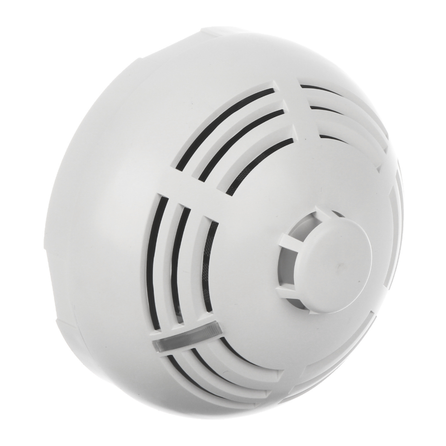
Figure 1

Figure 2
- EN54-7 compliant visible smoke sensor.
- EN54-5 compliant heat sensor.
- Red LED for optical signaling.
- Built-in sounder.
- Test feature.
- Tamper switch (supervised when working in the MICRA system).
SPECIFICATIONS
| Operating frequency band | 433.05 ÷ 434.79 MHz |
| Radio communication range (in open area) | up to 200 m |
| Battery | CR123A 3 V |
| Battery life expectancy | approx. 3 years |
| Standby current consumption | 50 µA |
| Maximum current consumption | 20 mA |
| Class according to EN 54-5 (heat sensor) | A1R |
| Minimum static response temperature | 54°C |
| Maximum static response temperature | 65°C |
| Operating temperature range | 0°C...55°C |
| Enclosure dimensions | ø108 x 61 mm |
| Weight | 170 g |
FUNCTIONAL DESCRIPTION
The MSD-300 multisensor detector can detect the early stages of fire development when there is some visible smoke and/or temperature rise. It can operate as a stand-alone device or in combination with the MICRA alarm module with firmware version 2.02 or newer. This manual applies to the detector with electronics version 1.1 or newer.
An optical method is used for the detection of visible smoke. When the concentration of smoke in the optical chamber exceeds a given threshold, an alarm is triggered. The smoke sensor operating parameters are modified depending on the temperature changes recorded by the heat sensor (thermistor). The heat sensor operates according to the requirements of Class A1R (EN 54-5). The alarm will be triggered after exceeding a certain threshold temperature (54°C – 65°C) or in the event when the temperature rises too rapidly (see Table 1).
Table 1. Response time limits for the heat sensor.
| Air temperature rise velocity | Lower limit of response time | Upper limit of response time |
| 1°C/min | 29 min | 40 min 20 s |
| 3°C/min | 7 min 13 s | 13 min 40 s |
| 5°C/min | 4 min 9 s | 8 min 20 s |
| 10°C/min | 1 min | 4 min 20 s |
| 20°C/min | 30 s | 2 min 20 s |
| 30°C/min | 20 s | 1 min 40 s |
The alarm is indicated visually (LED steady light) and acoustically (intermittent sound) for 2 minutes. Pressing the test / reset button (designated with the letter A in Figure 1) during the alarm will clear the alarm condition. The alarm information is sent by radio to the MICRA alarm module. After the alarm causes cease to exist, information about the alarm end will be sent. Every 15 minutes, the detector sends a transmission containing information on tamper contact and battery status. Periodic transmissions are used to monitor the presence and operation of the detector by the MICRA module.
INSTALLATION
The detector is designed for indoor operation. It should be installed on the ceiling, at a minimum distance of 0.5 meters from the walls or other objects.

Do not install the detector in places with high concentration of dust and/or formation and condensation of water steam. The detector should not be mounted in the vicinity of heaters and cookers.
The detector enclosure can not be closed without the battery inserted.
There is a danger of battery explosion when using a different battery than recommended by the manufacturer, or handling the battery improperly.
Be particularly careful during installation and replacement of the battery. The manufacturer is not liable for the consequences of incorrect installation of the battery.
The following description applies to installation of the detector which is to work within the MICRA system. If the detector is to operate stand-alone, skip steps 5 and 6.
- Remove the plastic dust cap.
- Turn the cover counter-clockwise (Fig. 1) and remove it (Fig. 2).
- Remove the battery and remove the protective film from it.
- Re-install the battery.
- Register the detector in the MICRA alarm module (see the manual for MICRA alarm module).
- Check that the transmissions from the detector placed in the selected mounting location reach the MICRA alarm module. To send a transmission, close and open the tamper contact. If the alarm transmission is received, proceed with the installation. If the alarm transmission is not received, select a different mounting location and repeat the test.
- Using wall plugs (screw anchors) and screws, fasten the enclosure base to the ceiling.
- Close the detector enclosure.
- Press and hold down the test / reset button (designated with the letter A in Figure 1) to make sure that the detector works. Alarm should be triggered after a few seconds.
- If any other operations which may cause contamination of the optical chamber are being carried in the facility where the detector is installed, the detector must be temporarily covered with a plastic dust cap.
CLEANING THE OPTICAL CHAMBER
The detector monitors the state of the optical chamber. Deposition of dust in the interior of the chamber can in time lead to false alarms. Contamination of the chamber is indicated by LED (2 flashes every 40 seconds). Information on the chamber soiling is sent to the MICRA module, which can notify the user about it. In order to clean the chamber, do as follows:
- If the detector is used in the MICRA system, start the test mode in the module.
- Turn the cover counter-clockwise (Fig. 1) and remove it (Fig. 2).
- Remove the battery.
- Pull aside the mounting catches and remove the electronics board with the optical chamber.
![]()
![]()
- Remove the cover from the thermistor.
![]()
- Pull aside the thermistor and its leads.
![]()
- Pull aside the mounting catch of the optical chamber and remove it.


- Using a soft brush or compressed air, clean the labyrinth in the cover and the base of the optical chamber, paying attention to the recesses where the LEDs are installed.
- Replace the cover of the optical chamber.
- Place the thermistor leads in the respective grooves.
- Replace the thermistor cover.
- Secure the electronics board with the optical chamber in the cover mounting catches. The board must be mounted so that the LED coincides with the light guide/button.
- Re-install the battery.
- Close the detector enclosure.


BATTERY REPLACEMENT
The detector power supply battery (CR123A 3 V) ensures operation for about 3 years. A low battery status (voltage drop to 2.6 V) is audibly indicated (by a beep every 40 seconds). The information on low battery is sent to the MICRA module, which can notify the user about it. To replace the battery, do as follows:
- If the detector is used in the MICRA system, start the test mode in the module.
- Turn the cover counter-clockwise (Fig. 1) and remove it (Fig. 2).
- Remove the discharged battery and dispose of in accordance with applicable environmental regulations.
- Install a new CR123A 3 V lithium battery.
- Close the detector enclosure.
- Press and hold down the test / reset button (designated with the letter A in Figure 1) to make sure that the detector works. Alarm should be triggered after a few seconds.
SATEL sp. z o.o.
ul. Schuberta 79; 80-172 Gdansk, POLAND
tel. +48 58 320 94 00; info@satel.pl; www.satel.eu

Documents / Resources
References
Download manual
Here you can download full pdf version of manual, it may contain additional safety instructions, warranty information, FCC rules, etc.
Download Satel MSD-300 - Wireless Smoke And Heat Detector Manual
Advertisement


Need help?
Do you have a question about the Micra MSD-300 and is the answer not in the manual?
Questions and answers