Table of Contents
Advertisement
Quick Links
Advertisement
Table of Contents

Related Manuals for BLACK NOISE QBI


Summary of Contents for BLACK NOISE QBI
- Page 2 Warranty BLACK NOISE warrants the contents of this kit to be free of defects in materials or workmanship and to be conform with the specifications at the time of shipment for a period of two years from the date of purchase.
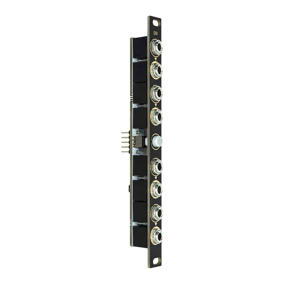
- Page 3 Build instructions Build instructions Prepare the micro-switch #3 Place the jack connectors Once the tabs are trimmed, look under the Place the jack connectors on the PCB. switch you will see a round mark. Pay Make sure to place the connector attention to this mark is important to modified during the previous step at correctly place your switch on the PCB.
- Page 4 Build instructions Build instructions Solder micro switch #1 Place the faceplate Place the faceplate and screw the nuts on To ensure that the micro-switch is the jack connectors. correctly aligned, solder the tab opposite to the first soldered as shown in the image below.
- Page 5 Set your multimeter to "continuity", For more information on connecting to connect one of the probe to one the the your rack and the possibilities of your QBI ground pin. Test +12V and -12V pins with consult the user manual accessible by the other probe.
Need help?
Do you have a question about the QBI and is the answer not in the manual?
Questions and answers