Table of Contents
Advertisement
Advertisement
Table of Contents

Related Manuals for Megger BITE 3


Summary of Contents for Megger BITE 3
- Page 1 AVTMBITE 3 Rev 8 April 2014 Instruction Manual BITE 3 Battery Impedance Test Equipment HIGH VOLTAGE EQUIPMENT Read this entire manual before operating. Valley Forge Corporate Center 2621 Van Buren Avenue Norristown, PA 19403-2329 U.S.A. 610-676-8500 www.megger.com...
- Page 3 BITE 3 Battery Impedance Test Equipment...
- Page 4 Specifications are subject to change without notice. WARRANTY Products supplied by Megger are warranted against defects in material and workmanship for a period of one year following shipment. Our liability is specifically limited to replacing or repairing, at our option, defective equipment.
-
Page 5: Table Of Contents
Step One: Perform Pre-Test Activities....................17 Step Two: Turning on the BITE 3 and Connecting the Lead Set............. 18 Step Three: Select a Site/String and Take Measurements..............19 Step Four: Perform Post-Test Activities....................19 ... - Page 6 Battery ................................28 Probe Tips............................... 28 Printer (Optional) ............................29 Configuration ..............................29 If the BITE 3 Needs Repairs ........................30 APPENDIX A - Technical Specifications ......................31 Electrical ................................31 Environmental..............................32 Safety ................................32 ...
-
Page 7: Introduction
These measurements, along with other maintenance data such as ambient and cell temperatures, help determine the condition of a battery system. The BITE 3 is the first instrument of its kind that can be configured through PC-based software, called Power DB This provides the ultimate in versatility and ease-of-use. -
Page 8: Electrical Theory And Practice
The BITE 3 generates data that describes an overall condition of a battery. Weak batteries are due to a number of reasons, some of which are sulfated plates, dry- out (loss-of-compression), loose intercell connectors, grid growth, etc. The BITE 3 also measures float current which increases over time as batteries degrade. In the case of VRLAs, increasing float current can indicate impending thermal runaway. -
Page 9: Applications For The Bite 3
Check the equipment received against the packing list to ensure that all materials are present. Notify Megger of any shortage (tel 1-610-676-8500.) The BITE 3 is easily operated by one technician. It is housed in a rugged plastic case. AVTMBITE 3 Rev 8 April 2014... -
Page 10: Safety First
Please examine the instrument for damage received in transit. If you find damage, file a claim with the carrier at once. Also notify Megger or our nearest authorized sales representative, and describe the damage in detail. Safety First Be sure to read the safety information in Chapter 2 thoroughly and observe all safety precautions and recommendations. -
Page 11: Safety
Any use of electricity inherently involves some degree of safety hazard. While Megger has made every effort to reduce the hazard, the operator must assume responsibility for his or her own safety. Any work on batteries is hazardous and requires constant attention to safety. -
Page 12: Cautions And Warnings
Cautions and Warnings This manual provides cautions and warnings where applicable, and these should be strictly observed. AVTMBITE 3 Rev 8 April 2014... -
Page 13: Controls, Connectors, Indicators & Menus
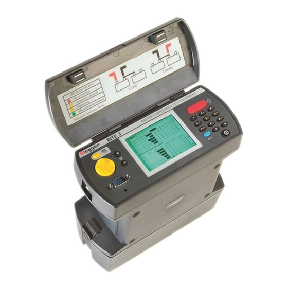
Electrical and Electronic Equipment. The Registration No is WEE/DJ2235XR. Overview The front panel of the BITE 3 comprises (clockwise from the top) the 1. Test button (used for optional lead sets) 2. Alpha-numeric keypad (symbols, too) 3. On-off switch, S1 (but it is not labeled S1.) 4. -
Page 14: Figure-1: Bite 3 Transceiver
The side panels comprise the lead set connection, J1 and the CT connection, J2. (again, the ports are not labeled Jx) Figure 2A: BITE 3 Fuse Figure-2: BITE 3 Lead Connections The battery charger connection, battery state indicator and slow charge control... -
Page 15: Switches And Connectors
Controls, Connectors, Indicators & Menus Figure-3: BITE 3 Battery Charger Connections Switches and Connectors S1 switch The on-off switch energizes/de-energizes the instrument. It takes about 30 seconds to boot-up and about ten seconds to shut down. J1 Lead set The lead sets are connected here. The connector is keyed. - Page 16 There is also an audible alarm in the instrument body and LEDs on the Dual- point Lead set to indicate circuit and measurement status. The following chart details the conditions under which the audible alarm and LEDs activate. The circuit and measurement status is also displayed on the LCD. No Circuit Yellow- Blinking Circuit found, not measuring...
- Page 17 The output current and the escape current, together, provide accurate impedance values. Other methods that do not measure current or the BITE 3 without the optional CT may have inherent errors. By measuring the “escape” current, that is, the current that is not passing through the battery being tested, it can be subtracted from the output current to correctly calculate impedance following Ohm’s Law, Z=E/i.
- Page 18 The flowchart of the menu structure: Analyze Configure System Measure New Test Analyze Instrument Select a String Select a Test About Instrument Name: (Test screen – starts with Select and Continue Name: Auto Off: (time in seconds) temp (manual entry), Close Version: Line Frequency: (Hz)
-
Page 19: The Battery Module
On the front of the battery module are two buttons and a 10-segment LED display. To find the amount of charge in your battery module, whether connected to your BITE 3 or separate, press the button. Battery Condition... - Page 20 However, you may wish to have a spare battery that can be interchanged with the one in use to provide continuous use of your BITE 3. As the battery ages, it may start to loose its capacity. In this case the battery...
- Page 21 Controls, Connectors, Indicators & Menus The battery is too hot or too cold and charging has therefore been interrupted until the battery returns to a temperature between 32°F and 115°F (0°C and 45°C). The stationary LEDs are flashing. Input Voltage Too Low: The charger supply is not supplying sufficient voltage to the battery module to charge the batteries.
- Page 22 AVTMBITE 3 Rev 8 April 2014...
-
Page 23: Test Procedures
TEST PROCEDURES Overview The BITE 3 is used to test a battery string while the dc system is on-line and floating. It can store measurements on a per cell/jar basis as well as per string basis. It has memory for about 22,000 60-cell strings in a database structure to keep track of all of the data. -
Page 24: Step Two: Turning On The Bite 3 And Connecting The Lead Set
The BITE 3 is a PC-based instrument running Windows CE. It will take about 30 seconds to boot up and be ready to take measurements. 1. Turn on the BITE 3 by pressing the on/off (O | I) button. The back light should stay lit. -
Page 25: Step Three: Select A Site/String And Take Measurements
Step Three: Select a Site/String and Take Measurements. 1. After a site/string has been selected, measure ambient temperature and enter it in the BITE 3. Press the “enter” key after typing the temperature. Measure I New Test BATTERY_LAB_SMALL_6 Air Temp: 0.000... -
Page 26: Reviewing A Test
CT in “Impedance” mode. Configure the CT mode in the BITE 3 for Impedance mode. Connect the CT to the BITE 3 and to any place within the string being tested. Then take the normal battery measurements as in Step Three above. -
Page 27: Reviewing And Retesting
Test Procedures 5. Continue testing cells and straps as necessary, making appropriate connections and pushing the red "test" button on the top panel of the BITE 3 to start the measurements. 6. Once the measurement is complete, continue testing until all cells/jars have been tested. - Page 28 AVTMBITE 3 Rev 8 April 2014...
-
Page 29: Interpreting Test Results
Interpreting Test Results Overview The BITE 3 interfaces with Power DB; which allows you to download data from the unit, update sites and string information as well as update firmware in the BITE3. Power DB maintains data from all customers, regions, sites and strings whereas the BITE 3 manages a “subset”... -
Page 30: Instantaneous Mode Of Analysis
cable. Turn on the printer and follow the menus again, highlight “print” and press the enter key. Instantaneous Mode of Analysis If no previous data were measured, then a weak cell can only be found by comparing each cell against the string average, called deviation. The allowable percent deviation depends upon the battery technology: flooded Lead-acid or VRLA. -
Page 31: Short-Term Mode Of Analysis
Interpreting Test Results Short-term Mode of Analysis In some cases, previous data were taken but doesn’t start at battery commissioning. In this scenario, a comparison between each cell and its previous measurement, called percent change, aids in determining its condition. Additionally, use the deviation as an additional piece of information to get a better determination of the condition of the string. - Page 32 AVTMBITE 3 Rev 8 April 2014...
-
Page 33: Maintenance And Trouble Shooting
MAINTENANCE AND TROUBLE SHOOTING Overview The BITE 3 is designed to meet the rigors of battery testing in industrial environments. It is housed in a durable ABS/PS case as are the probes. It uses a Windows CE operating system with on-board diagnostics. There is very little that can go wrong. -
Page 34: Battery
UK in accordance with Local Authority requirements. For disposal of batteries in other parts of the EU contact your local distributor. Megger is registered in the UK as a producer of batteries. The Registration number is BPRN01235. -
Page 35: Printer (Optional)
Maintenance and Trouble Shooting Printer (Optional) Configuration To print a paper copy of the existing printer settings: While holding down the "On-Line" switch, turn on the printer. The following list will print (factory default settings shown). Figure-5: Printer Configuration Printout If you want to leave the settings as they are, press the "FEED"... -
Page 36: If The Bite 3 Needs Repairs
If the BITE 3 Needs Repairs Megger offers a complete repair service. Call Customer Service at 1-610-676- 8500 to obtain an RMA number before shipment. Include all standard and optional accessories to ensure that all possible sources of problems can be investigated. -
Page 37: Appendix A - Technical Specifications
APPENDIX A - Technical Specifications Electrical Impedance Range and Resolution 0.05 to 1.000 m 1 μ resolution 1 to 10.00 m 10 μ resolution 10 to 100.0 m 0.1 m resolution Voltage Range and Resolution 1 to 15 VDC across probes 1 to 8.0 V dc 1 mV resolution 8.0 to 15 VDC 10 mV resolution Current Range and Resolution... -
Page 38: Environmental
Environmental Operating: 32° to 105° F (0° to +40° C) Storage: -5° to 130° F (-20° to +55° C) Humidity: 20 to 90% RH, non-condensing Safety Designed to meet IEC 61010-1 specifications Mechanical Dimensions: 200 H x 100 W x 240 D mm (9.5 H x 8.6 W x 4 D x 9.5 H inches) Weight: 5.7 lbs (2.6 kg) -
Page 39: Appendix B - Replaceable Parts
APPENDIX B - Replaceable Parts The BITE 3 as delivered includes all of the necessary basic accessories to test most battery configurations. However, the number of battery configurations is large. In order to satisfy many of the other battery configurations, a range of optional accessories is offered. - Page 40 AVTMBITE 3 Rev 8 April 2014...
-
Page 41: Appendix C - Compatibility
APPENDIX C - Compatibility Hardware – Unit Firmware Compatibility Operating System PC104 Firmware Versions Supported OLD WINDOWS CE OLD PC104 Versions 1 – 1.9.2.99 NEW WINDOWS CE OLD PC104 Version 2 & even numbers ONLY NEW WINDOWS CE NEW PC104 Version 3 &... -
Page 42: Firmware Modifications
Firmware Modifications Firmware Hardware Code 2.000 OLD PC-104 NEW OS System. Corrects Contrast Issue. Unit remembers contrast setting at turn off. Incorporates both Russian and Vietnamese languages into the unit. 3.000 NEW PC-104 NEW OS SYSTEM. Corrects Contrast Issue. Unit remembers contrast setting at turn off.
Need help?
Do you have a question about the BITE 3 and is the answer not in the manual?
Questions and answers