
Subscribe to Our Youtube Channel
Related Manuals for bioMerieux BACT/ALERT 3D 60


Summary of Contents for bioMerieux BACT/ALERT 3D 60
- Page 1 6 6 0 0 T A L L E E R R T T 3 3 D D A A C C Service Manual bioMérieux, Inc. Box 15969, Durham, NC 27704-0969 http://www.biomerieux.com © BIOMÉRIEUX 2002 Manual Part Number 48001-6 Rev A March 2003...
- Page 2 BacT/ALERT® 3D 60 All Rights Reserved Worldwide Printed in the United States of America No part of this publication may be used or reproduced in any form, electronic or written via database or retrieval system, without the prior written permission of bioMérieux. Documenting copies of any part of this publication, for any purpose other than for which has been authorized in advance, is in strict violation of United States copyright laws.
- Page 3 BacT/ALERT® 3D 60 This document will be updated for each software modification or any other change. Information supplied in this document is subject to modification before the products described become available. ® This document may contain information or references concerning certain bioMérieux products, programs and services not available in certain countries;...
- Page 4 BacT/ALERT® 3D 60 THIS PAGE INTENTIONALLY LEFT BLANK Service Manual...
-
Page 5: Table Of Contents
BacT/ALERT® 3D 60 TABLE OF CONTENTS TABLE OF CONTENTS FRONT MATTER........................IX APPENDICES.........................IX LIST OF TABLES......................XI LIST OF ILLUSTRATIONS..................XIII TYPOGRAPHY AND GRAPHIC CONVENTIONS............. XIX 0.4.1 Bullets ......................xxi 0.4.2 Text Boxes ....................... xxi 0.4.3 Bracketed Italics....................xxi 0.4.4 Underlined Text....................xxi 0.4.5 Bracketed Text.................... - Page 6 TABLE OF CONTENTS BacT/ALERT® 3D 60 GENERAL INFORMATION ....................1-1 INTRODUCTION......................1-1 REFERENCE DATA.....................1-2 EQUIPMENT DESCRIPTION..................1-3 ASSEMBLY DESCRIPTIONS..................1-4 1.4.1 Electrical Components..................1-4 1.4.1.1 Power Panel Assembly..............1-5 1.4.1.2 Transformer Assembly..............1-5 1.4.1.3 Heater ....................1-5 1.4.1.4 Blower....................1-5 1.4.1.5 Step-5 Motor Assembly ..............1-7 1.4.1.6 Fan ....................1-7 1.4.1.7 Quick Reference Card ..............1-7 1.4.2...
- Page 7 BacT/ALERT® 3D 60 TABLE OF CONTENTS 1.4.4 Input / Output Devices ..................1-16 1.4.4.1 Operator Display Monitor ...............1-17 1.4.4.2 Barcode Scanner ................1-17 1.4.4.3 Keyboard ..................1-17 1.4.4.4 Zip Drive ..................1-17 1.4.4.5 56K FAX Modem (Domestic)............1-19 1.4.4.6 56K Fax Modem (International) ............1-19 1.4.5 Uninterruptible Power Supply “UPS”..............1-20 1.4.5.1 On/Off Switch................1-21...
- Page 8 TABLE OF CONTENTS BacT/ALERT® 3D 60 INSTALLATION PROCEDURES ..................3-1 INTRODUCTION......................3-1 BACT/ALERT 3D 60 INSTALLATION PROCEDURES..........3-3 3.2.1 Verification of Site Requirements................3-3 3.2.2 Record Line Noise.....................3-3 3.2.3 Unpacking ......................3-3 3.2.4 Repacking ......................3-3 3.2.4.1 Verification of Contents..............3-6 3.2.4.1.1 3D 60 Instrument Parts..........3-6 3.2.5...
- Page 9 MB CONVERSION PROCEDURE................4-5 4.4.1 Overview ......................4-5 4.4.2 Procedure......................4-5 DATA BACKUP/RESTORE PROCEDURES..............4-9 4.5.1 BacT/ALERT 3D 60 - Data Backup Procedure ............4-9 4.5.2 BacT/ALERT 3D 60 - Data Restore Procedure............4-9 PREVENTIVE MAINTENAN CE .................4-11 4.6.1 Overview ......................4-11 4.6.2 Perform Data Backup ..................4-11 4.6.3...
- Page 10 TABLE OF CONTENTS BacT/ALERT® 3D 60 SOFTWARE DIAGNOSTICS..................4-15 4.8.1 Button Legend ....................4-15 4.8.2 Purpose of the Section ..................4-16 4.8.3 Special Equipment ..................4-16 4.8.4 Accessing the Diagnostics Screens ..............4-17 4.8.5 Diagnostic Screens Overview................4-18 ALIGNMENTS AND CALIBRATIONS...............4-69 4.9.1 Overview ......................4-69 4.9.2 System Power Supply..................4-69 4.9.3 Temperature ....................4-69 4.9.4...
- Page 11 BacT/ALERT® 3D 60 TABLE OF CONTENTS 4.10.14 Power Supply Transformer (P/N 851-0015-01) ..........4-126 4.10.15 Power Supply MOV - Metal Oxide Varistor (P/N 43116-2) ........ 4-128 4.10.16 Power Panel Solid State Relays (P/N 845-0018-01) ........4-130 4.10.17 DC Power Supply (P/N 852-0010-01) ............. 4-132 4.10.18 Power Entry Module (PEM) Fuses (P/N 870-0008-14, -17, -24, -25) ....
- Page 12 TABLE OF CONTENTS BacT/ALERT® 3D 60 THIS PAGE INTENTIONALLY LEFT BLANK viii Service Manual...
-
Page 13: Front Matter
BacT/ALERT® 3D 60 TABLE OF CONTENTS Appendix A GLOSSARY ..................Appendix B PARTS LIST ..................Alphabetical Listing ................. Appendix C DISINFECTION .................. Introduction ..................C.1 Procedures..................C.1 Spills ..................... C.1 Instrument Shipping................C.1 Assembly Shipping ................C.1 Appendix D ERROR CODES ................. Appendix E DIAGRAMS.................. - Page 14 TABLE OF CONTENTS BacT/ALERT® 3D 60 THIS PAGE INTENTIONALLY LEFT BLANK Service Manual...
-
Page 15: List Of Tables
BacT/ALERT® 3D 60 TABLE OF CONTENTS Section 1 Table 1.2.1 Reference Data ..................1-2 Section 2 Table 2.2.1 Audio Frequency Selection (JP 23 through JP26) ........2-4 Table 2.5.1 Power Supply Data .................2-10 Section 3 Table 3.2.1 3D 60 instrument Parts List ...............3-6 Table 3.2.2 Facility Power Rating and Conversion Chart... - Page 16 TABLE OF CONTENTS BacT/ALERT® 3D 60 THIS PAGE INTENTIONALLY LEFT BLANK Service Manual...
-
Page 17: List Of Illustrations
Blower & Heater................................1-4 Fig. 8 - Step-5 Motor Assembly..............................1-6 Fig. 9 - Fan Assembly ................................1-6 Fig. 10 - BacT/ALERT 3D 60 System Control (Rear View) w/Comm Ports..............1-8 Fig. 11 - CPU PCBA ................................1-10 Fig. 12 - ModSig PCBA ................................1-10 Fig. 13 - Quad Serial PCBA..............................1-10... - Page 18 TABLE OF CONTENTS BacT/ALERT® 3D 60 CHAPTER 2 – BACKGROUND INFORMATION Fig. 33 - ModSig PCBA Diagram ............................2-2 Fig. 34 - ModSig Block Diagram............................2-5 Fig. 35 - Thermistor PCBA..............................2-6 Fig. 36 - Power Distribution Block Diagram........................2-8 Fig. 37 - CPU PCBA Diagram ...............................2-12 Fig.
- Page 19 BacT/ALERT® 3D 60 TABLE OF CONTENTS Fig. 70 - 1.5 Inc Module 1/Temperature Log (Text String Output)................4-20 Fig. 71 - 1.5 Inc Module 1/Temperature Log (Save Output to Zip) ................4-20 Fig. 72 - 1.5 Inc Module 1/Temperature Log (Scroll/Anchor Buttons) ..............4-21 Fig.
- Page 20 TABLE OF CONTENTS BacT/ALERT® 3D 60 Fig. 120 - ModSig – Rear Panel Screw Removal......................4-100 Fig. 121 - ModSig PCBA – Mounting Screw Locations ....................4-101 Fig. 122 - ModSig – Step-5 MCJ4 Connection ......................4-102 Fig. 123 - ModSig –...
- Page 21 BacT/ALERT® 3D 60 TABLE OF CONTENTS Fig. 170 - Power Supply Panel – BHP1 Connector...................... 4-144 Fig. 171 - Power Supply Panel – HBJ1/HBP1 Connector ..................4-144 Fig. 172 - Power Supply Panel – Mounting Screw Removal..................4-145 Fig. 173 - Blower Motor Capacitor –...
- Page 22 TABLE OF CONTENTS BacT/ALERT® 3D 60 THIS PAGE INTENTIONALLY LEFT BLANK xviii Service Manual...
-
Page 23: Typography And Graphic Conventions
BacT/ALERT® 3D 60 TYPOGRAPHY AND GRAPHIC CONVENTIONS The following is a comprehensive list of the typographical and graphic elements of this manual. TYPOGRAPHY AND GRAPHIC CONVENTIONS............. XIX 0.4.1 Bullets ......................xxi 0.4.2 Text Boxes ....................... xxi 0.4.3 Bracketed Italics....................xxi 0.4.4 Underlined Text.................... - Page 24 TYPOGRAPHY AND GRAPHICS CONVENTIONS BacT/ALERT® 3D 60 THIS PAGE INTENTIONALLY LEFT BLANK Service Manual...
-
Page 25: Bullets
BacT/ALERT® 3D 60 TYPOGRAPHY AND GRAPHIC CONVENTIONS Bullets are used to designate items in a list (•, -) or steps in a procedure (1, 2, etc) Important Steps A text box can be a NOTE, CAUTION, WARNING or Image Note. Fig. -
Page 26: Bracketed Text
TYPOGRAPHY AND GRAPHIC CONVENTIONS BacT/ALERT® 3D 60 Single text within brackets identifies single keys to be pressed on the keyboard. (I.E.: Press <Esc> to exit the system.) Whenever text is displayed within q uotation marks, it usually means that this a displayed message on the screen. -
Page 27: Safety Summary
BacT/ALERT® 3D 60 SAFETY SUMMARY The following is a comprehensive list of the safety issues outlined in this chapter. SAFETY SUMMARY ....................XXIII 0.5.1 General Information to Follow ................xxv 0.5.2 Electrical Warnings ................... xxv 0.5.3 Electrical Grounding ..................xxvi 0.5.4 Fuse Replacement Warning ................xxvi 0.5.5 Hazardous Voltages ..................xxvi... -
Page 28: Safety Summary
SAFETY SUMMARY BacT/ALERT® 3D 60 THIS PAGE INTENTIONALLY LEFT BLANK xxiv Service Manual... -
Page 29: Electrical Warnings
(See Subsection 3.2.5 – Set AC Power) Whenever it is likely that a BacT/ALERT 3D 60 has been impaired, it will be made inoperative by powering it down and disconnecting the power cord. If there is evidence of moisture within the instrument, turn the facility power off at the circuit breaker junction box before removing the power cable. -
Page 30: Electrical Grounding
At the time of installation, the customer does install PEM fuses according to steps outlined in the Installation section of the BacT/ALERT 3D 60 Operator’s Manual. DC voltages used within the instrument are low voltage and low current. They do not pose any immediate hazard to technicians. -
Page 31: Health Risks
BacT/ALERT® 3D 60 SAFETY SUMMARY Specimens and inoculated culture bottles are to be assumed as though they are capable of transmitting infectious agents. Handling of any bottles or specimens must be done with the utmost care. Spills must be cleaned as soon as possible, using the disinfection procedures ®... - Page 32 SAFETY SUMMARY BacT/ALERT® 3D 60 THIS PAGE INTENTIONALLY LEFT BLANK xxviii Service Manual...
- Page 33 BacT/ALERT® 3D 60 CHAPTER 1 – GENERAL INFORMATION C H A P T E R 1 G E N E R A L I N F O R M A T I O N...
- Page 34 CHAPTER 1 – GENERAL INFORMATION BacT/ALERT® 3D 60 THIS PAGE INTENTIONALLY LEFT BLANK Service Manual...
-
Page 35: General Information
BacT/ALERT® 3D 60 1 – GENERAL INFORMATION This chapter describes the theory of operation and the general characteristics of the equipment. The following is a comprehensive list of the general descriptions of instrument components, operational reference data, subassemblies and operator display configurations. GENERAL INFORMATION .................... -
Page 36: Reference Data
1 – GENERAL INFORMATION BacT/ALERT® 3D 60 This chart represents the environmental conditions for use, including the physical, functional and technical characteristics of the BacT/ALERT 3D 60 instrument. Electrical Power Service Required 100/120/220/240VAC @ 50/60Hz Power Consumed In Watts 120VAC: 480W Max... -
Page 37: Equipment Description
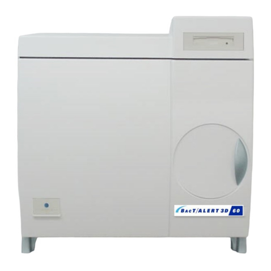
The instrument consists of a WinSystems CPU and one 60-bottle chamber consisting of three racks of 20 culture bottles each. An externally attached display monitor permits the operator to control and monitor the racks. (Refer to Figure 4, below) Fig. 4 - BacT/ALERT 3D 60 Instrument Service Manual... -
Page 38: Assembly Descriptions
1 – GENERAL INFORMATION BacT/ALERT® 3D 60 The following paragraphs indicate the composition of the system, (i.e., the equipment, hardware, software and consumables required for it to operate. Relays DC Power Supply Transformer Fig. 5 - 3D 60 Power Panel Assembly Fig. -
Page 39: Power Panel Assembly
1 – GENERAL INFORMATION BacT/ALERT® 3D 60 1.4.1.1 Power Panel Assembly ® The BacT/ALERT 3D 60 instrument uses a standard BTA cabinet power supply. The Power Panel Assembly provides the AC and DC power supply voltages that are used within the 3D 60. With the use of relays, this will also shut down incubation processes when instructed to do so by the ModSig PCBA. -
Page 40: Fig. 8 - Step-5 Motor Assembly
1 – GENERAL INFORMATION BacT/ALERT® 3D 60 Step-5 Motor Fig. 8 - Step-5 Motor Assembly Fig. 9 - Fan Assembly Service Manual... -
Page 41: Step-5 Motor Assembly
1 – GENERAL INFORMATION BacT/ALERT® 3D 60 1.4.1.5 Step-5 Motor Assembly This Step-5 Motor (Figure 8) provides agitation to the racks, unless the incubation chamber has been converted to MB and the motor has been disconnected to bypass this process. (Refer to Subsection 4.4.2, Figures 59, 60 and 61 for MB Conversion) 1.4.1.6... -
Page 42: Communications Ports (Input / Output)
1 – GENERAL INFORMATION BacT/ALERT® 3D 60 Fig. 10 - BacT/ALERT 3D 60 System Control (Rear View) w/Comm Ports Service Manual... -
Page 43: Comm Port
1 – GENERAL INFORMATION BacT/ALERT® 3D 60 The communications ports are input/output ports that peripheral devices connect to on the rear of the BacT/ALERT 3D 60 instrument. (Refer to Figure 10) 1.4.2.1 COMM Port This port is reserved for future use. -
Page 44: Electronic Components
1 – GENERAL INFORMATION BacT/ALERT® 3D 60 CPU Board ModSig Board Fig. 11 - CPU PCBA Fig. 12 - ModSig PCBA Quad Serial Board Thermistor Board Fig. 13 - Quad Serial PCBA Fig. 14 - Thermistor PCBA 1-10 Service Manual... -
Page 45: Cpu Pcba
1 – GENERAL INFORMATION BacT/ALERT® 3D 60 The Electronics Compartment is situated in the top part of the 3D 60 instrument. It contains ® the internal WinSystems computer (CPU PCBA and Quad Serial PCBA), CompactFlash Adapter PCBA, Zip™ Drive, Step-5 PCBA and the ModSig PCBA. 1.4.3.1 CPU PCBA The CPU is a 586 processor with an operating clock speed of 133MHz. -
Page 46: Fig. 15 - Compactflash Memory Disk
1 – GENERAL INFORMATION BacT/ALERT® 3D 60 Fig. 15 - CompactFlash Memory Disk Fig. 16 - CompactFlash Adapter PCBA NOTE: Flash memory disk above may not necessarily reflect the actual memory disk or size being used in the 3D 60 instrument. Fig. -
Page 47: Compactflash Memory Disk
BacT/ALERT 3D 60. The adapter provides for master/slave selection and a visual drive status indicator. The CompactFlash Adapter PCBA is installed on the top cover of BacT/ALERT 3D 60 system. 1.4.3.7 Step-5 PCBA The Step-5 controller board (Reference Figure 17) is designed to drive a five-phase stepper motor at the speed of 60 revolutions per minute. -
Page 48: Fig. 18 - Bact 3D 60 Incubator Chamber
1 – GENERAL INFORMATION BacT/ALERT® 3D 60 Fig. 18 - BacT 3D 60 Incubator Chamber Fig. 19 - Rack Assembly 1-14 Service Manual... -
Page 49: Incubator Chamber Components
1 – GENERAL INFORMATION BacT/ALERT® 3D 60 1.4.3.8 Incubator Chamber Components The Incubation Chamber (Reference Figure 18) contains three specimen racks, relays, power supply, ModSig PCBA, rack controller PCBAs, heater and blower. As viewed by the operator, the bottles are loaded into the front of the 3D 60 instrument. 1.4.3.8.1 Rack Each rack contains 20 bottle cells. -
Page 50: Input / Output Devices
1 – GENERAL INFORMATION BacT/ALERT® 3D 60 Fig. 20 - Operator Display Monitor Fig. 21 - Barcode Scanner Note: The figure above shows a flat panel monitor and may not represent the model or type of monitor actually shipped with the 3D 60 instrument. Fig. -
Page 51: Operator Display Monitor
1 – GENERAL INFORMATION BacT/ALERT® 3D 60 1.4.4.1 Operator Display Monitor The display monitor is a standard VGA monitor used for displaying diagnostic and module setup information. (Reference Figure 20) 1.4.4.2 Barcode Scanner The QuickScan™ 6000 Barcode Scanner scans bottle labels, identifying the bottles whenever loading or unloading. - Page 52 1 – GENERAL INFORMATION BacT/ALERT® 3D 60 THIS PAGE INTENTIONALLY’ LEFT BLANK 1-18 Service Manual...
-
Page 53: Fax Modem (Domestic)
1 – GENERAL INFORMATION BacT/ALERT® 3D 60 1.4.4.5 56K FAX Modem (Domestic) The fax modem serves as an interface to the BacT 3D 60 instrument for remote access. The remote user is able to download and upload information, including seeing what is on the display-screen that the local operator views. -
Page 54: Uninterruptible Power Supply "Ups
1 – GENERAL INFORMATION BacT/ALERT® 3D 60 “ ” “ ” Computer Interface Port Telephone Surge Protection Overload On/Off Switch Protector 120V Backup Receptacles Test Switch Accessory Surge Receptacles Fig. 24 - Uninterruptible Power Supply (UPS) Domestic Model – Front and Rear Views 1-20 Service Manual... -
Page 55: On/Off Switch
Refer to Figure 24 for the following component descriptions of the domestic UPS. 1.4.5.1 On/Off Switch Turns the UPS and BacT/ALERT 3D 60 unit ON and OFF from the UPS. 1.4.5.2 UPS Comm Port (Computer Interface Port) The UPS Computer Interface Port is a standard 9-pin port used to connect a cable that monitors communications between the UPS and the 3D 60 Instrument. -
Page 56: Fig. 25 - Uninterruptible Power Supply (Ups) European Model - Front And Rear Views
1 – GENERAL INFORMATION BacT/ALERT® 3D 60 “ ” “ ” Computer Interface Port Overload Protector On/Off Switch Accessory Surge Receptacle Test Switch 240V Backup Receptacles Fig. 25 - Uninterruptible Power Supply (UPS) European Model – Front and Rear Views 1-22 Service Manual... - Page 57 1 – GENERAL INFORMATION BacT/ALERT® 3D 60 “ ” “ ” The European UPS model is very similar to the US domestic model. The voltage rating, power cord and fuse ratings, however, are for the European power conversions. (Refer to Figure 25 for International/European UPS components) Service Manual 1-23...
-
Page 58: Operator Display Configuration Screens
1 – GENERAL INFORMATION BacT/ALERT® 3D 60 Fig. 26 - Instrument Configuration Screen 1-24 Service Manual... -
Page 59: Fig. 27 - Main Screen
1 – GENERAL INFORMATION BacT/ALERT® 3D 60 The BacT/ALERT 3D 60’s Operator’s Manual describes most of the screens displayed on the display monitor. Specifically, it describes the screens used to: load/unload bottles, set the date and time, enable/disable cells, calibrate incubation temperature, perform single cell calibration, set maximum test times, set audible alarm options and change passwords. -
Page 60: Instrument Configuration Screen
1 – GENERAL INFORMATION BacT/ALERT® 3D 60 1.5.1.1 Accessing the Configuration Screen (Continued) Key button Password Key buttons System Setup Screen Configure Screen button Previous Screen button Fig. 28 - Setup Screen w/Field Engineer Password Activation Clicking on the [Configure Screen] button will access the “Configuration Screen”. NOTE To get back to the Main Screen, press the [Previous Screen] button. -
Page 61: Configuration Screen [X Box] Buttons
1 – GENERAL INFORMATION BacT/ALERT® 3D 60 1.5.1.3 Configuration Screen [X Box] Buttons Several configuration options are represented by a graphical element called an [X Box] button. As shown in Figure 30 below, an [X Box] button can appear with or without an “X”... - Page 62 1 – GENERAL INFORMATION BacT/ALERT® 3D 60 THIS PAGE INTENTIONALLY LEFT BLANK 1-28 Service Manual...
-
Page 63: Quick Reference Card
1 – GENERAL INFORMATION BacT/ALERT® 3D 60 The Quick Reference Card ( F igure 31 Figure 32 on the following pages, Front and Rear Sides, respectively) is simply that…a quick reference. The card contains references to errors and ® fault codes that may appear on the BacT/ALERT 3D 60 during operation. -
Page 64: Fig. 31 - Quick Reference Card - Front Side
1 – GENERAL INFORMATION BacT/ALERT® 3D 60 Card P/N 955-0500-03 Rev A OPERATION ERROR CODES Refer to Operator Manual for detailed error description and troubleshooting instructions. Code Description Code Description CORRUPTED BOTTLE RECORD HAS BEEN SELEC TED BOTTLE ID SCANNED MATCHES THAT OF A PREVIOUSLY UNLOADED BOTTLE REQUIRED DATA MISSING INVALID CELL LOAD... -
Page 65: Fig. 32 - Quick Reference Card - Rear Side
1 – GENERAL INFORMATION BacT/ALERT® 3D 60 INSTRUMENT FAULT AND STATUS CODES Refer to Operator Manual for detailed error description and troubleshooting instructions. Code Description Code Description POWER FAULT IN INCUBATION MODULE CELL FAILED QC COMMUNICATION LOST WITH INCUBATION MODULE ERRONEOUS CELL LOAD STATUS REPORTED INCUBATION MODULE TEMPERATURE IS TOO HIGH INVALID TIME STAMP... - Page 66 1 – GENERAL INFORMATION BacT/ALERT® 3D 60 THIS PAGE INTENTIONALLY LEFT BLANK 1-32 Service Manual...
- Page 67 BacT/ALERT® 3D 60 CHAPTER 2 – BACKGROUND INFORMATION C H A P T E R 2 B A C K G R O U N D I N F O R M A T I O N Service Manual...
- Page 68 CHAPTER 2 – BACKGROUND INFORMATION BacT/ALERT® 3D 60 THIS PAGE INTENTIONALLY LEFT BLANK Service Manual...
-
Page 69: Background Information
BacT/ALERT® 3D 60 2 – BACKGROUND INFORMATION The following is a comprehensive list of items outlined in this chapter. Included are the system PCBAs and the function of each, as well as the Incubation Chamber and Power Supply. BACKGROUND INFORMATION ..................2-1 INTRODUCTION......................2-1 SYSTEM CONTROL - MODSIG PCBA...............2-2 THERMISTOR PCBA (INPUT/OUTPUT)..............2-6... -
Page 70: System Control - Modsig Pcba
2 – BACKGROUND INFORM ATION BacT/ALERT® 3D 60 Fig. 33 - ModSig PCBA Diagram Service Manual... - Page 71 BacT/ALERT® 3D 60 2 – BACKGROUND INFORMATION The MODSIG PCBA provides interfaces to the 3D 60 Instrument Controller section, the Step-5 board, external peripherals and the Rack PCBA’s. It uses a 68HC11 microprocessor with firmware stored in the EPROM. The microprocessor uses an external 16 MHz crystal for its clock.
-
Page 72: Table 2.2.1 Audio Frequency Selection (Jp 23 Through Jp26)
2 – BACKGROUND INFORM ATION BacT/ALERT® 3D 60 FREQUENCY JP23 JP24 JP25 JP26 600 Hz 800 Hz 1 KHz 1.5 KHz 3 KHz Table 2.2.1 - Audio Frequency Selection (JP23 through JP26) Service Manual... - Page 73 BacT/ALERT® 3D 60 2 – BACKGROUND INFORMATION Step-5 PCBA • Door Interlock Switches • +5 Power • Agitate ON 32KB RAM FROM: Step- 5 PCBA • Error Signal 68HC11 32KB RAM • Blower ON • Heater ON Heater Inlet/Outlet • Agitate ON Drivers Temperature...
-
Page 74: Thermistor Pcba (Input/Output)
2 – BACKGROUND INFORM ATION BacT/ALERT® 3D 60 Fig. 35 - Thermistor PCBA Service Manual... - Page 75 BacT/ALERT® 3D 60 2 – BACKGROUND INFORMATION The Thermistor board uses an Analog device AD592BN temperature transducer to produce a current flow proportional to temperature. The voltage source is +9VDC. The temperature transducer has a nominal flow of 298.2µa+ 25ºC. There are two Thermistors PCBAs in the 3D 60 instrument.
- Page 76 2 – BACKGROUND INFORM ATION BacT/ALERT® 3D 60 Power Distribution Block Diagram Facility Power Power Isolation Entry Transformer Module Blower TB 1 Heater Elec. Comp. Common Logic Ground Return 3 DC Power +5 VDC E Fan CPU PCBA Supply Relay -12 VDC Heater Relays...
- Page 77 BacT/ALERT® 3D 60 2 – BACKGROUND INFORMATION Input power for the 3D 60 (Refer to Figure 36) is either 115 VAC or 220 VAC. The installation technician sets the proper voltage selection at the Power Entry Module (PEM). The circuitry is protected by one 6.3A “time-delay”...
-
Page 78: Dc Power Supply
2 – BACKGROUND INFORM ATION BacT/ALERT® 3D 60 Parameter Condition Limits Input Voltage 85 - 264 VAC Input Frequency Range 47 - 440 Hz Input Surge Current Cold Start, 110 VAC/220 VAC 17 A maximum/ 34A maximum ± 3% Output Voltage Adjustability +5.1 VDC output (Supply Only) PIN CHART AC Ground... - Page 79 BacT/ALERT® 3D 60 2 – BACKGROUND INFORMATION The BacT/ALERT 3D 60’s power supply is a quad output switcher intended for small to medium- sized digital systems. These power supplies also contain built-in over-voltage protection and a “power fail detect” signal.
-
Page 80: Cpu Pcba
2 – BACKGROUND INFORM ATION BacT/ALERT® 3D 60 LITHIUM KEEPER LTC-3PN Fig. 37 - CPU PCBA Diagram 2-12 Service Manual... - Page 81 BacT/ALERT® 3D 60 2 – BACKGROUND INFORMATION ® The CPU PCBA ( R eference Figure 37) is an “off-the-shelf” internally mounted WinSystems computer that combines a 586 (or higher) CPU with Video, Floppy, IDE, Serial and Digital I/O. The chipset provides the core logic that makes the board PC/AT software compatible. It includes the DRAM controller, bus interface, integrated peripheral controllers (8237 DMA, 82C54 timer, 82C59 PIC, RTC, KYBD controller and CMOS memory) and an internal PCI bus for high-speed operation.
-
Page 82: Compactflash Adapter Pcba
2 – BACKGROUND INFORM ATION BacT/ALERT® 3D 60 Fig. 38 - CompactFlash Adapter PCBA 2-14 Service Manual... - Page 83 BacT/ALERT® 3D 60 2 – BACKGROUND INFORMATION A CompactFlash Adapter PCBA (with CompactFlash Memory Disk™ installed) is mounted near ® the WinSystems motherboard. It is connected by a flat ribbon cable to the motherboard’s IDE port. (Refer to Figure 38 Subsection 4.10.4, Figures 108-112) ®...
-
Page 84: Quad Serial Interfac E Pcba
2 – BACKGROUND INFORM ATION BacT/ALERT® 3D 60 Copyright 1995 Made in USA ® WinSystems PCM-COM4A Rev. B Fig. 39 - Quad Serial Interface PCBA Diagram 2-16 Service Manual... - Page 85 BacT/ALERT® 3D 60 2 – BACKGROUND INFORMATION The Quad Serial Interface (Com4) board ( Reference Figure 39) is a daughter board that plugs ® into the PC/104 bus on the WinSystems motherboard. There are four ports on the board. Com 1 is configured as a RS-485 port. Com 2 3 and 4 are configured as RS-232 ports.
-
Page 86: Rack Controller Pcba
2 – BACKGROUND INFORM ATION BacT/ALERT® 3D 60 Fig. 40 - Rack Controller PCBA Diagram 2-18 Service Manual... - Page 87 BacT/ALERT® 3D 60 2 – BACKGROUND INFORMATION The Rack Controller PCBA ( Refer to Figure 40), u sing EPROM-stored software, controls the excitation LEDs. The LED light illuminates and reflects on the bottle sensors, creating emitted measurable values at the photo detectors. The Rack Controller digitizes each cell’s photo- detector output for reading by the ModSig’s Control Module and for bottle presence detection.
- Page 88 2 – BACKGROUND INFORM ATION BacT/ALERT® 3D 60 Rack Controller Block Diagram Agitation 32 KB Sensor Cell 32 KB 68HC11 Microprocessor Sensors OP Amps 1-20 w/internal RAM and EPROM Analog Multiplexer Cell Drivers Exciters Constant Rack Current 1-20 Temperature Control Cell Indicators 12-Bit...
- Page 89 BacT/ALERT® 3D 60 2 – BACKGROUND INFORMATION Each cell has an individual external sensor. The sensor outputs are multiplexed to cascaded operational amplifiers that drive the analog input of an A-D Converter. The cell sensor readings are sent, on request, to the instrument. The Rack Controller firmware detects bottle presence from these photodiode sensors as well.
- Page 90 2 – BACKGROUND INFORM ATION BacT/ALERT® 3D 60 Rack Address Concept JP10 ModSig PCBA + 5V + 5V Polling line connects via JP2 on each Rack PCBA RACK #2 RACK #3 RACK #1 Rack #1 Address Code Rack #2 Address Code Rack #3 Address Code Input pins 18-17-16 Input pins 18-17-16...
- Page 91 BacT/ALERT® 3D 60 2 – BACKGROUND INFORMATION A 12-bit A-D Converter is provided to convert the rack temperature sensor’s analog signals to the digital signals used by the Rack Controller software. The same A-D Converter is used for converting cell sensor analog signals into digital signals. Using the +2.5V reference voltage, the resistor voltage dividers, an operational amplifier and a MOSFET controls the current for the exciter LEDs.
-
Page 92: Step-5 Pcba
2 – BACKGROUND INFORM ATION BacT/ALERT® 3D 60 Fig. 43 - Step-5 PCBA Diagram 2-24 Service Manual... - Page 93 BacT/ALERT® 3D 60 2 – BACKGROUND INFORMATION The Step-5 controller board ( R eference Figure 43) is designed to drive a five-phase stepper motor at the speed of 60 revolutions per minute. The board operates with input voltages of +5V and +12V, drives the stepper motor directly, and provides starting and stopping functions based on inputs received from the ModSig PCBA.
- Page 94 2 – BACKGROUND INFORM ATION BacT/ALERT® 3D 60 Motor Output: The PM589 motor is a 5-phase stepper, wired in a pentagon configuration, 500 steps per revolution in full step mode. Step sequence example for the 5 phases is: PHASE 1 PHASE 2 PHASE 3 PHASE 4...
- Page 95 BacT/ALERT® 3D 60 2 – BACKGROUND INFORMATION Motor voltage fault: If the motor supply voltage goes off, the microcontroller will turn off motor drive until the motor supply is restored. Power up protection: The high side predriver transistors require that the 16C74 source current to turn them on.
- Page 96 2 – BACKGROUND INFORM ATION BacT/ALERT® 3D 60 INDEPENDENT SAFETY TIMER INTERLOCKS Microchip POSITION PIC16C74 SENSOR DRIVE MOTOR STOP/RUN COMMAND MOSFETS (FROM MODULE CONTROLLER) HIGH-SIDE DC IN PREDRIVERS FAULT OUTPUT Fig. 44 - Step-5 PCBA Block Diagram 2-28 Service Manual...
- Page 97 BacT/ALERT® 3D 60 CHAPTER 3 – INSTALLATION PROCEDURES C H A P T E R 3 I N S T A L L A T I O N P R O C E D U R E S Service Manual...
- Page 98 CHAPTER 3 – INSTALLATION PROCEDURES BacT/ALERT® 3D 60 THIS PAGE INTENTIONALLY LEFT BLANK Service Manual...
-
Page 99: Installation Procedures
BacT/ALERT® 3D 60 3 – INSTALLATION PROCEDURES This paragraph presents the Installation Procedures chapter contents. INSTALLATION PROCEDURES ..................3-1 INTRODUCTION......................3-1 BACT/ALERT 3D 60 INSTALLATION PROCEDURES..........3-3 RESTRAINT INSTALLATION..................3-14 SOFTWARE INSTALLATION..................3-17 SWITCHING ON......................3-17 Service Manual... -
Page 100: Installation Procedures
3 – INSTALLATION PROCEDURES BacT/ALERT® 3D 60 THIS PAGE INTENTIONALLY LEFT BLANK Service Manual... -
Page 101: Bact/Alert 3D 60 Installation Procedures
(es) in which the equipment is delivered. Unpacking instructions are illustrated on every instrument’s shipping carton. The unpacking instructions may also be found in the BacT/ALERT 3D 60 Operator’s Manual. Defective 3D 60 instruments, demo and show units, will require carton repacking for return shipments. - Page 102 3 – INSTALLATION PROCEDURES BacT/ALERT® 3D 60 Fig. 45 - 3D 60 Instrument Repacking Sequence Service Manual...
- Page 103 BacT/ALERT® 3D 60 3 – INSTALLATION PROCEDURES – – Fig. 46 - 3D 60 Instrument Repack - Web Strapping Diagrams Service Manual...
-
Page 104: Verification Of Contents
3 – INSTALLATION PROCEDURES BacT/ALERT® 3D 60 3.2.4.1 Verification of Contents After unpacking the unit and parts, inspect contents of the BacT/ALERT 3D 60 for shipping damage. Refer to Table 3.2.1 below for parts content listing. 3.2.4.1.1 3D 60 Instrument Parts These parts are shipped separately or with the unit. -
Page 105: Set Ac Power
BacT/ALERT® 3D 60 3 – INSTALLATION PROCEDURES Perform the Power Entry Module (PEM) fuse replacement procedure to set proper voltage settings. Refer to steps 1-8 below. After setting proper voltage and installing proper fuse(s), discard the remaining fuse(s). NOTE The Power Entry Module (805-0017-02) is located in the rear and lower left corner of the instrument. -
Page 106: Table 3.2.2 Facility Power Rating And Conversion Chart
3 – INSTALLATION PROCEDURES BacT/ALERT® 3D 60 Install the fuse(s) for the proper voltage rating. Reinstall the fuse holder. Close the PEM cover. Below you will find Table 3.2.2, an installation guide showing specific Facility Power Ratings and the proper fuse installation figure to use. Facility Power Rating Figure to Use 110 Volts AC... -
Page 107: Restraint Installation
BacT/ALERT® 3D 60 3 – INSTALLATION PROCEDURES Assemble and install the 3D 60 Instrument in the specified installation location. NOTE If countertop or other permanent (bolted) installation is required, see Section 3.3 - Restraint Installation. Place the UPS near the 3D 60 Instrument. Connect the UPS 9-pin control cable from the Accessory Kit to the 9 -pin connector on the rear of the UPS labeled “Computer Interface Port”. -
Page 108: Fig. 21 - Barcode Scanner
3 – INSTALLATION PROCEDURES BacT/ALERT® 3D 60 Installation and Set-up Diagram – Port and Power Connections PRINTER MOUSE BARCODE SCANNER Communications Panel COMM MOUSE PRINTER BARCODE KEYBRD MODEM SERIAL UPS MONITOR EXT SPKR Surge outlets SPEAKERS with Battery Backup KEYBRD MODEM MONITOR Telephone... -
Page 109: Temperature
BacT/ALERT® 3D 60 3 – INSTALLATION PROCEDURES Press the top of the UPS (toggle) power switch to ON. Power up the display monitor. Power on the 3D 60 instrument by turning on the Main Power switch on the rear of the instrument. Refer to Figure 51 for Main Power switch and PEM location on the rear of the unit) Power up the modem and printer. - Page 110 3 – INSTALLATION PROCEDURES BacT/ALERT® 3D 60 Set the modem’s DIPswitches. (Refer to Figure 53 for DIP Switch settings.) When modem and telephone connections are available, connect the Modem Interface cable between the modem connector and the port labeled “Modem” (located on the bulkhead on the rear of the instrument).
- Page 111 BacT/ALERT® 3D 60 3 – INSTALLATION PROCEDURES On the instrument’s monitor screen, click the [Load Bottle] button on the Main Menu. Scan a bottle and verify that the scanned number matches the bottle. Press the [Done] button to exit the [Load Bottle] mode. Perform UPS test.
-
Page 112: Restraint Installation
3 – INSTALLATION PROCEDURES BacT/ALERT® 3D 60 The countertop mounting hardware consists of screws and flat washers used to attach the instrument to a countertop or other surface of variable thickness. (Refer to Table 3.3.3 for required parts.) ITEM QUANTITY ¼”... -
Page 113: Table 3.3.4 Table Of Equivalent Dimensions
BacT/ALERT® 3D 60 3 – INSTALLATION PROCEDURES For mounting surfaces up to 2 ¼” thick you can use the 5 inch bolts supplied with the instrument. For mounting surfaces or surfaces requiring longer bolts, you can use the “Table of Equivalent Dimensions” and Figure 54 - Mounting Surface Diagram, to determine the required bolt length. - Page 114 3 – INSTALLATION PROCEDURES BacT/ALERT® 3D 60 Drill 1/2” Holes. Four places. Rear clearance: 5” from hole, or 4” from instrument. Top View Note: Door will 13” swing 3 1/2” wide. Left side clearance: Allow 4 ½” from left Front side of hole.
-
Page 115: Software Installation
CompactFlash Adapter PCBA. The following steps offer suggested power up and device power cord connection procedures for the BacT/ALERT 3D 60 instrument. Proper battery hookup and installation of the UPS is required prior to taking the following steps below. - Page 116 3 – INSTALLATION PROCEDURES BacT/ALERT® 3D 60 ® BacT/ALERT 3D 60 Installation Checklist SITE NAME ________________________________ SERIAL # _____________________ CITY, STATE _______________________________ SERVICE CALL #_______________ Pass Initials Site Requirements are met ____ _____ Unpack and Verify Contents ____ _____ Restraint Installation (if required) ____ _____ AC Power Configuration...
- Page 117 BacT/ALERT® 3D 60 CHAPTER 4 – SERVICING C H A P T E R 4 S E R V I C I N G Service Manual...
- Page 118 CHAPTER 4 – SERVICING BacT/ALERT® 3D 60 THIS PAGE INTENTIONALLY LEFT BLANK Service Manual...
-
Page 119: Servicing
BacT/ALERT® 3D 60 4 – SERVICING This paragraph presents the Servicing chapter contents. Subjects include tools required for servicing, PMs, Power Up/Down Procedures, Software Diagnostics and general maintenance or repair. SERVICING......................... 4-1 INTRODUCTION......................4-1 SPECIFIC TOOLS AND REQUIRED................4-3 POWER UP/DOWN PROCEDURES................4-3 MB CONVERSION PROCEDURE................4-5 DATA BACKUP/RESTORE PROCEDURES..............4-9 PREVENTIVE MAINTENAN CE .................4-11... -
Page 120: Servicing
4 – SERVICING BacT/ALERT® 3D 60 THIS PAGE INTENTIONALLY LEFT BLANK Service Manual... -
Page 121: Specific Tools And Required
BacT/ALERT® 3D 60 4 – SERVICING The following is a list of the tools required for maintenance of the instrument: • Calibrated Digital Voltmeter (DVM) capable of measuring .01 VDC • Calibrated Thermometer, NIST traceable and accurate to ± .5°C •... - Page 122 Shutdown complete After the DOS prompt appears, power can be removed by accessing the PEM’s Main Power Switch on the rear of the BacT/ALERT 3D 60 instrument. Turn the Main Power Switch, located on the Power Entry Module (PEM), to OFF.
-
Page 123: Mb Conversion Procedure
BacT/ALERT® 3D 60 4 – SERVICING By removing power from the agitation (Step-5) motor and anchoring the linkage assembly that rocks the racks, the incubation chamber can be converted to a stationary (MB) configuration. Refer to Subsection 4.3.2 and perform the 3D 60 Power Down procedure. Remove the two screws securing the Top Panel and secure it into the “Up”... - Page 124 4 – SERVICING BacT/ALERT® 3D 60 Move Agitation Arm to lowest position (as shown here), to install the Lock Screw in Hole #2 for MB Conversion. MB Conversion Lock Screw Hole #2 MB Conversion Lock Screw – Hole #1 MB Conversion Installation Location (Original Location for Agitation Mode) Remove the screw from this location and install into Hole #2...
- Page 125 BacT/ALERT® 3D 60 4 – SERVICING Ensure Agitation Arm is at its lowest position (as shown here), to align and install the Lock Screw in Hole #2 for MB Conversion. MB Conversion Lock Screw – Hole #2 (Installed Location for MB Conversion) NOTE Racks may have to be rocked slightly, forward or backward, in order to align...
- Page 126 4 – SERVICING BacT/ALERT® 3D 60 THIS PAGE INTENTIONALLY LEFT BLANK Service Manual...
- Page 127 BacT/ALERT® 3D 60 4 – SERVICING Refer to the BacT/ALERT 3D 60 Operator’s Manual and NOTE box, below. Go to “Setup” screen. Enter password numbers “<4><3><4><3><2><1><2><1>” Click on the BACKUP MANAGEMENT [Setup] button. (Refer to Figure 62) Fig. 62 - Backup Management Button Insert the backup disk into the Zip drive.
- Page 128 4 – SERVICING BacT/ALERT® 3D 60 THIS PAGE INTENTIONALLY LEFT BLANK 4-10 Service Manual...
-
Page 129: Data Backup/Restore Procedures
BacT/ALERT® 3D 60 4 – SERVICING: PREVENTIVE MAINTENANCE This section refers to the descriptions of preventive maintenance operations. The Preventive Maintenance (PM) procedure has been provided for personnel trained by bioMérieux. PMs are required to be performed annually, unless specified otherwise. Refer to Section 4.5 –... -
Page 130: Door Open" Test
4 – SERVICING: PREVENTIVE MAINTENANCE BacT/ALERT® 3D 60 Observe 3D 60 power off. After the instrument powers off, restore power to the UPS. Verify that the instrument retains correct time and has no visible errors displaced on the monitor screen. “... -
Page 131: Diagnostics And Troubleshooting
It also describes the remedial action to be taken to return the instrument to serviceable condition. This section pertains to the symptomatic problems that may appear during normal operation of the BacT/ALERT 3D 60. These errors will cause an error code to appear. Error Code information can be found in Appendix D of this manual or the BacT/ALERT 3D 60 Operator’s... - Page 132 4 – SERVICING: DIAGNOSTICS AND TROUBLESHOOTING BacT/ALERT® 3D 60 PROBLEM CAUSE SOLUTION The Barcode Scanner needs to be Scan the Barcode label in Figure reprogrammed default Barcode Scanner does not beep settings. Barcode Scanner is defective. Replace Barcode Scanner Fuse is blown. Check and replace F2 on the ModSig PCBA.
-
Page 133: Software Diagnostics
BacT/ALERT® 3D 60 4 – SERVICING: SOFTWARE DIAGNOSTICS Set Date/Time Button Edit Cell Contents Button Enable/Disable Module, Drawer, Calibrate Cell Button Rack or Cell Button Calibrate Module Temperature Button View Incubation Module Information Button Backup Management Button Set Maximum Test Time Button Set Audible Alarm Options Button Edit Data Relationships Button Change Password Button... -
Page 134: Purpose Of The Section
4 – SERVICING: SOFTWARE DIAGNOSTICS BacT/ALERT® 3D 60 • This document describes the various diagnostics built into version B.11 of the BacT/Alert 3D-instrument controller software. These diagnostics apply to the standard 3D 60 instrument. • This document serves as design specifications for the software implementation. •... - Page 135 BacT/ALERT® 3D 60 4 – SERVICING: SOFTWARE DIAGNOSTICS • Starting from the Main screen, click on the [Next] button in the lower right corner of the screen to access the Setup screen. • Using the numbered buttons at the top of the Setup screen, enter the password <1><2><1><2><3><4><3><4>, and click on the button with the key icon to access the Diagnostic Selection screen.
- Page 136 4 – SERVICING: SOFTWARE DIAGNOSTICS BacT/ALERT® 3D 60 • All diagnostics screens have the same general form. An example screen is shown below. Diagnostic Name Operation Buttons Run continuously Pause / Run once Find text Save output to ZIP Print all output Print current page Diagnostic output Cancel print...
- Page 137 BacT/ALERT® 3D 60 4 – SERVICING: SOFTWARE DIAGNOSTICS Date and Time [DD/MM/YY HH:MM:SS] Date and time displayed is the local time. displayed in day, month, year, hour, minute, and second order, regardless of the settings on the SET DATE/TIME menu. Help line: Some diagnostic accept keystroke data to invoke special functions.
- Page 138 4 – SERVICING: SOFTWARE DIAGNOSTICS BacT/ALERT® 3D 60 For example, if the search text entered is 1B21 and the “Check” button is clicked, the original diagnostic screen appears and the display area is scrolled to the first instance of that text. The text is highlighted in white. First instance listing of 1B21 Press [F3] on your...
-
Page 139: Fig. 22 - Keyboard
BacT/ALERT® 3D 60 4 – SERVICING: SOFTWARE DIAGNOSTICS A default file name is automatically entered for you. By default the data is saved on the ZIP disk in a subdirectory named DIAGDUMP. The file name corresponds to the number of the diagnostic that is currently selected. If you wish to use another filename, touch the “destination filename entry box”, press the SPACE bar to clear the box and then type in the desired name. - Page 140 4 – SERVICING: SOFTWARE DIAGNOSTICS BacT/ALERT® 3D 60 Slide bar The raised section of the Slidebar indicates the position of the displayed data and is relative to the amount of total display data area. The size of the raised portion of the Slide bar is proportional to the amount of display data in relationship to the total amount of data (including scrollable data).
-
Page 141: Special Equipment
BacT/ALERT® 3D 60 4 – SERVICING: SOFTWARE DIAGNOSTICS 1 Inc Module 1 Inc Module 1 / Loopback Screen ® ® Special equipment Loopback method 1: (not applicable to Combo or 3D 60 1) Disconnect the cable between IC and IM, at IM end 2) Bring cable out to front and attach 43013-1 ®... - Page 142 4 – SERVICING: SOFTWARE DIAGNOSTICS BacT/ALERT® 3D 60 Fig. 74 - 1.1 Inc Module 1/Loopback Test Screen Display values Should increment - Number of transmit buffer empty interrupts seen by serial hardware. Should increment - Number of receive buffer full interrupts generated by serial hardware. Should remain at 0 - Number of line status interrupts generated by serial hardware.
- Page 143 BacT/ALERT® 3D 60 4 – SERVICING: SOFTWARE DIAGNOSTICS Inc Module 1 / Port Stats Screen Special equipment None Description This diagnostic displays statistics for the serial hardware that is used to communicate with a given incubation module Impact Bottle testing is not affected by this diagnostic Test Procedure Keyboard functions [R] –...
- Page 144 4 – SERVICING: SOFTWARE DIAGNOSTICS BacT/ALERT® 3D 60 Inc Module 1 / Message Stats Screen Special equipment None Description Displays statistics related to messages exchanged between the instrument controller and incubation module. Also displays statistics related to incubation module power faults and event requests.
- Page 145 BacT/ALERT® 3D 60 4 – SERVICING: SOFTWARE DIAGNOSTICS Inc Module 1 / Message Log Screen Special equipment None Description Displays the recent history of commands and responses exchanged between the instrument controller and incubation module. Impact Bottle testing is not affected by this diagnostic Test Procedure Keyboard functions None...
- Page 146 4 – SERVICING: SOFTWARE DIAGNOSTICS BacT/ALERT® 3D 60 Inc Module 1 / Temperature Log Screen Special equipment None Description Display history or heater temperature sensors and sensor on the racks Impact Bottle testing is not affected by this diagnostic Test Procedure Keyboard functions None Run status...
- Page 147 BacT/ALERT® 3D 60 4 – SERVICING: SOFTWARE DIAGNOSTICS Inc Module 1 / Reading Log Screen Special equipment None Description Displays recent history of readings taken Impact Bottle testing is not affected by this diagnostic Test Procedure Keyboard functions None Run status Run continually and adds new readings to end of display as they occur Displays the most recent readings taken on incubation module cells.
- Page 148 4 – SERVICING: SOFTWARE DIAGNOSTICS BacT/ALERT® 3D 60 Inc Module 1 / Flag Check Screen Special equipment None Description This diagnostic gathers calibration information for all the cells in an incubation module. Specifically, the current flag reading and the flag reading at calibration time are obtained.
- Page 149 BacT/ALERT® 3D 60 4 – SERVICING: SOFTWARE DIAGNOSTICS Once all of the required data is gathered, the “diff %” data is displayed (as shown on the adjacent screen). This screen groups the cells by the Cells whose amount (Delta) that their flag difference is greater than or equal to reading differs from its expected...
- Page 150 4 – SERVICING: SOFTWARE DIAGNOSTICS BacT/ALERT® 3D 60 Inc Module 1 / Incubation Heater Screen Special equipment None Description This diagnostic displays the state of the drawer switch and heater function in an incubation module. Impact Bottle testing is not affected by this diagnostic Test Procedure Keyboard functions None...
- Page 151 BacT/ALERT® 3D 60 4 – SERVICING: SOFTWARE DIAGNOSTICS Inc Module 1 / LED Check Screen Special equipment None Description This diagnostic provides a way to turn all the LEDs (both drawer and cells) ON and also to blink them in a pattern to verify that they all work and that no LEDs are shorted together.
- Page 152 4 – SERVICING: SOFTWARE DIAGNOSTICS BacT/ALERT® 3D 60 THIS PAGE INTENTIONALLY LEFT BLANK 4-34 Service Manual...
- Page 153 BacT/ALERT® 3D 60 4 – SERVICING: SOFTWARE DIAGNOSTICS INSTRUMENT CNTRL INSTRUMENT CNTRL / ZIP Drive Test Screen Special equipment None Description This verifies that data can be written to (and read from) the ZIP drive Impact Bottle testing is not affected by this diagnostic Test Procedure a) Remove ZIP disk from ZIP drive and replace with known good ZIP disk b) Start diagnostic...
- Page 154 4 – SERVICING: SOFTWARE DIAGNOSTICS BacT/ALERT® 3D 60 INSTRUMENT CNTRL / Barcode Loopback Screen Special equipment PN 43012-1 Description This diagnostic verifies the operation of the serial hardware that makes up the interface to the bar code scanner. It isolates problems to either the barcode scanner or instrument controller.
- Page 155 BacT/ALERT® 3D 60 4 – SERVICING: SOFTWARE DIAGNOSTICS This value can be ignored - It is displayed for diagnosis of software activity and indicates whether the software’s transmit data FIFO is empty or not (1 or 0 respectively Should remain at 0/0/0 - Displayed for purpose of diagnosing software activity and indicates whether there was fault storing data in the software’s transmit data FIFO and where in the code that fault occurred.
- Page 156 4 – SERVICING: SOFTWARE DIAGNOSTICS BacT/ALERT® 3D 60 INSTRUMENT CNTRL / Modem Loopback Screen Special equipment P/N 43012-1 Description This diagnostic verifies that the operation of the serial hardware that makes up the interface to the external modem. It isolates problems to either the external modem or instrument controller.
- Page 157 BacT/ALERT® 3D 60 4 – SERVICING: SOFTWARE DIAGNOSTICS INSTRUMENT CNTRL / Power event log screen Special equipment None Description Shows recent history of power events, including power faults, in the instrument controller and incubation module Impact Bottle testing is not affected by this diagnostic Test Procedure Keyboard functions None...
- Page 158 4 – SERVICING: SOFTWARE DIAGNOSTICS BacT/ALERT® 3D 60 INSTRUMENT CNTRL / View files screen Special equipment None Description Allows contents of selected files to be viewed Impact Bottle testing is not affected by this diagnostic Test Procedure Keyboard functions Selects the file that is to be viewed [1] –...
- Page 159 BacT/ALERT® 3D 60 4 – SERVICING: SOFTWARE DIAGNOSTICS .BID files Similar to 7.5.1 with the exception that files in the c:\btlprocs directory with a .BID extension are displayed. .BTF files Similar to 7.5.1 with the exception that files in the c:\btlprocs directory with a .BTF extension are displayed.
- Page 160 4 – SERVICING: SOFTWARE DIAGNOSTICS BacT/ALERT® 3D 60 Each line in an event log has the same format as follows: !! 127829789(18/01/01 13:24:00) 0x38(DTO) 82349 seconds dd/mm/yy hh:mm:ss event info 4-42 Service Manual...
- Page 161 BacT/ALERT® 3D 60 4 – SERVICING: SOFTWARE DIAGNOSTICS The event info content varies (depending on the kind of event) and is described below. Software exception Exception details 0x1(SWExc) LOG,TEST,MAIN This event occurs if there is a condition, for example a hardware problem that the software cannot handle, or there is a design flaw in the software that results in a condition that cannot be handled.
- Page 162 4 – SERVICING: SOFTWARE DIAGNOSTICS BacT/ALERT® 3D 60 Backup started 0x100(BkupStart) This event is logged any time a backup has started. Backup completed successfully 0x101(BkupOk) This event is logged any time that a backup is completed successfully Backup failed 0x102(BkupFailed) This event is logged any time that a backup has started but failed to complete successfully Operator cell calibration Module...
- Page 163 BacT/ALERT® 3D 60 4 – SERVICING: SOFTWARE DIAGNOSTICS Remote User requests shutdown 0x205(RemUserSD) This event is logged any time that the software is shutdown because of a request passed by the Remote User software. Set the setpoint Module Number New Setpoint temperature 0x500(MTSet) 37.0...
- Page 164 4 – SERVICING: SOFTWARE DIAGNOSTICS BacT/ALERT® 3D 60 INSTRUMENT CNTRL / Software Screen Special equipment None Description Displays data used to debug, verify and validate instrument software. Also, displays logs of exception conditions detected by the software. Impact Bottle testing is not affected by this diagnostic Test Procedure Keyboard functions Selects the specific type of information to display...
- Page 165 BacT/ALERT® 3D 60 4 – SERVICING: SOFTWARE DIAGNOSTICS Association tables Displays current content of various dictionaries and association tables used to keep track of bottle and pre-load data. An example of the Association screen content is shown below. Explanatory comments are shown in italics and do not actually appear on the diagnostic screen.
- Page 166 4 – SERVICING: SOFTWARE DIAGNOSTICS BacT/ALERT® 3D 60 --- PRELOAD: ACC to RecNum Dictionary --- release an accession to the one record number in the preload file that has that accession 191, AH4ACC*1, 2 hash table index, accession, preload file rec num 275, AH3ACC*8895AFA, 1 4-48 Service Manual...
- Page 167 BacT/ALERT® 3D 60 4 – SERVICING: SOFTWARE DIAGNOSTICS Bottle processing tables Displayed the current content of the tables that drive the way the 3D processes bottles. An example is shown below. *** Bottle Processing Tables Log *** ------------ Bottle IDs Table (76 entries) ---------- Prefix, Min, Max, BottleType, Container Type ZINHI, 5, 15, 23, 2 ZBLYM, 5, 8, 16, 2...
- Page 168 4 – SERVICING: SOFTWARE DIAGNOSTICS BacT/ALERT® 3D 60 ZA, 5, 8, 2, 1 IA, 8, 8, 50, 2 Prefix, Min, Max, BottleType, Container Type IN, 8, 8, 51, 2 IL, 8, 8, 52, 2 9, 0, 0, 0, 0 8, 0, 0, 0, 0 7, 0, 0, 0, 0 6, 0, 0, 0, 0 5, 0, 0, 0, 0...
- Page 169 BacT/ALERT® 3D 60 4 – SERVICING: SOFTWARE DIAGNOSTICS 47, Q47, Q47, 0, 3, 0, 10, 5, 11 48, Q48, Q48, 0, 3, 0, 10, 5, 11 49, Q49, Q49, 0, 3, 0, 10, 5, 11 50, BTA-I AST, ISA, 0, 2, 0, 5, 5, 11 51, BTA-I NST, ISN, 0, 2, 0, 5, 5, 11 52, BTA-I LYM, ILYM, 0, 2, 0, 9, 9, 15 53, Q53, Q53, 0, 3, 0, 10, 5, 11...
- Page 170 4 – SERVICING: SOFTWARE DIAGNOSTICS BacT/ALERT® 3D 60 FastCntrThres(12) FastBcktThres(0.105E2) FastBcktInc(1) FastRateThres(32) FastRateInc(3) FastDgdr(0.93E0) FastSlopProp(0.825E0) FastMayThres(3) SlowStupThres(12) SlowCntrThres(16) SlowBcktThres(15) SlowBcktInc(1) SlowDgdr(0.98E0) SlowSlopProp(0.9083E0) 2 ID(G2) BltFact(0.1E1) Resv(1320) MinSkipPts(216) MinAvgPts(24) MinAvgMed(1) SlopProp(0.1E0) SlowSlopProp(0.2E-1) FastDgdr(0.75E0) SlowDgdr(0.9E0) AcelSlopThres(20) SlowSlopThres(10) PosDlyThres(1) DltThres(100) NumAlg2Pts(576) PosSlopDly(720) DltDgdr(0.995E0) --- Embedded E2 Parms --- ID(E2) BltFact(0.1E1) Resv(1320) AdjThres(70) AdjLim(4) StupPts(5) StupSumx(15) StupDenom(50)
- Page 171 BacT/ALERT® 3D 60 4 – SERVICING: SOFTWARE DIAGNOSTICS SlopProp(0.1E0) SlowSlopProp(0.2E-1) FastDgdr(0.75E0) SlowDgdr(0.9E0) AcelSlopThres(20) SlowSlopThres(10) PosDlyThres(1) DltThres(100) NumAlg2Pts(576) PosSlopDly(720) DltDgdr(0.995E0) --- Embedded E2 Parms --- ID(E2) BltFact(0.1667E1) Resv(1320) AdjThres(70) AdjLim(4) StupPts(5) StupSumx(15) StupDenom(50) FastPts(17) FastSumx(153) FastDenom(6936) InitThres(6000) FastStupThres(6) SlopStupThres(0.1E1) FastCntrThres(12) FastBcktThres(0.105E2) FastBcktInc(1) FastRateThres(32) FastRateInc(3) FastDgdr(0.93E0) FastSlopProp(0.825E0) FastMayThres(3) SlowStupThres(12) SlowCntrThres(16) SlowBcktThres(15) SlowBcktInc(1)
- Page 172 4 – SERVICING: SOFTWARE DIAGNOSTICS BacT/ALERT® 3D 60 MinSkipPts(6) 13 ID(G3) BltFact(0.231E1) Resv(1320) MinSkipPts(216) MinAvgPts(24) MinAvgMed(1) SlopProp(0.1E0) SlowSlopProp(0.2E-1) FastDgdr(0.75E0) SlowDgdr(0.9E0) AcelSlopThres(20) SlowSlopThres(10) PosDlyThres(1) DltThres(100) NumAlg3Pts(576) PosSlopDly(720) DltDgdr(0.995E0) --- Embedded H2 Parms --- ID(H2) BltFact(0.231E1) Resv(1320) AdjThres(70) AdjLim(4) StupPts(5) StupSumx(15) StupDenom(50) FastPts(17) FastSumx(153) FastDenom(6936) InitThres(8300) FastStupThres(6) SlopStupThres(0.1E1) FastCntrThres(12) FastBcktThres(0.105E2) FastBcktInc(1)
- Page 173 BacT/ALERT® 3D 60 4 – SERVICING: SOFTWARE DIAGNOSTICS PosSlopDly(720) DltDgdr(<1.0E-32) --- Embedded H2 Parms --- ID(H2) BltFact(0.1667E1) Resv(1320) AdjThres(70) AdjLim(4) StupPts(5) StupSumx(15) StupDenom(50) FastPts(17) FastSumx(153) FastDenom(6936) InitThres(6000) FastStupThres(6) SlopStupThres(0.1E1) FastCntrThres(12) FastBcktThres(0.105E2) FastBcktInc(1) FastRateThres(32) FastRateInc(3) FastDgdr(0.93E0) FastSlopProp(0.825E0) FastMayThres(3) SlowStupThres(12) SlowCntrThres(16) SlowBcktThres(15) SlowBcktInc(1) SlowDgdr(0.98E0) SlowSlopProp(0.9083E0) MinSkipPts(6) 18 not used...
- Page 174 4 – SERVICING: SOFTWARE DIAGNOSTICS BacT/ALERT® 3D 60 77 not used 78 not used 79 not used 80 not used 81 not used 82 not used 83 not used 84 not used 85 not used 86 not used 87 not used 88 not used 89 not used 90 not used...
- Page 175 BacT/ALERT® 3D 60 4 – SERVICING: SOFTWARE DIAGNOSTICS 7.0 days ( 604800 secs.) Type = Q46 (46) 7.0 days ( 604800 secs.) Type = Q47 (47) 7.0 days ( 604800 secs.) Type = Q48 (48) 7.0 days ( 604800 secs.) Type = Q49 (49) 7.0 days ( 604800 secs.)
- Page 176 4 – SERVICING: SOFTWARE DIAGNOSTICS BacT/ALERT® 3D 60 14 LES/Glass (0x2000) Display BACT/ALERT FN 15 LES/Plastic (0x2001) Display BACT/ALERT PF 16 LES/Glass (0x2000) Display BACT/ALERT LYM 17 LES/Glass (0x4000) Display BACT/ALERT MP 18 LES/Glass (0x6000) Display BACT/ALERT MB 19 LES/Glass (0x4000) 20 LES/Glass (0x4000)
- Page 177 BacT/ALERT® 3D 60 4 – SERVICING: SOFTWARE DIAGNOSTICS 85 LES/Glass (0x6000) 86 LES/Glass (0x6000) 87 LES/Glass (0x6000) 88 LES/Glass (0x6000) 89 LES/Glass (0x6000) 90 LES/Glass (0x6000) 91 LES/Glass (0x6000) 92 LES/Glass (0x6000) 93 LES/Glass (0x6000) 94 LES/Glass (0x6000) 95 LES/Glass (0x6000) 96 LES/Glass (0x6000)
- Page 178 4 – SERVICING: SOFTWARE DIAGNOSTICS BacT/ALERT® 3D 60 Configuration tables Displays the configuration settings that are used to determine the 3D’s operation. All configuration settings are shown, regardless of whether the value was read from one of the .INI files or whether the value is a default value. An example is shown below. *** Configuration Data Log *** [DEBUG] LockNeverUsedList=0...
- Page 179 BacT/ALERT® 3D 60 4 – SERVICING: SOFTWARE DIAGNOSTICS FlagResultOnUnload=0 FlagResultOnPositive=1 FlagResultOnNegative=1 FlagResultOnLoad=0 AutoTransmitResults=0 Bidirectional=1 BitsPerChar=8 StopBits=1 Parity=0 BaudRate=48 Enabled=0 [DBMS] Enabled=1 Service Manual 4-61...
- Page 180 4 – SERVICING: SOFTWARE DIAGNOSTICS BacT/ALERT® 3D 60 Scandisk Output Scan [9] Misc Fig. 89 - 7.6 Instrument Cntrl/Software Test Screen - Scan Scandisk, as its name implies, is a function that runs periodically to check the integrity of the C and D drives. For the C: drive, an addition set of checks is made to verify the size of the fixed size files associated with the 3D application.
- Page 181 BacT/ALERT® 3D 60 4 – SERVICING: SOFTWARE DIAGNOSTICS VolID = 981014277 Vol Label = NO NAME FileSysType = FAT16 --- Computed data --- FAT Type = 16 FAT Size = 245 Total Secs = 250336 Bytes/FATEnt = 2 RootDirSector= 491 RootDirSectrs= 32 DataSector = 523...
- Page 182 4 – SERVICING: SOFTWARE DIAGNOSTICS BacT/ALERT® 3D 60 CHECK FIXED SIZED FILES ******************************************************** C:\CPUNVRAM.BIN expected / actual size 524288 / 524288 C:\CPUNVR2.BIN expected / actual size 524288 / 524288 C:\SSDNVRAM.BIN expected / actual size 2097152 / 2097152 C:\SSDNVR2.BIN expected / actual size 2097152 / 2097152 C:\READDATA\READINGS.DAT expected / actual size 70656512 / 70656512 ******************************************************** FILE SIZE CHECK PASSED...
- Page 183 BacT/ALERT® 3D 60 4 – SERVICING: SOFTWARE DIAGNOSTICS Cluster count ---------------------------- CHECK FILE STRUCTURES ---------------------------- Check file 100-1D.RKP Check file 100-1E.RKP Check file 100-1F.RKP Traverse subdirectory MTOUCH62 Check file MCAL.BAT Check file MCAL.OVL ---------------------------- CHECK FREE SPACE ---------------------------- Check free space for clusters 2 to 61117 ******************************************************** SCANDISK PASSED for drive D: Time = 10/12/01 09:14:34...
- Page 184 4 – SERVICING: SOFTWARE DIAGNOSTICS BacT/ALERT® 3D 60 Misc Scan [9] Misc Fig. 90 - 7.6 Instrument Cntrl/Software Test Screen – Misc. Display values Percentage of time the processor is idle Percentage of time processor is executing task code Percentage of time processor is executing interrupts of operating system code Amount of bytes left in heap Number of free blocks in heap Largest block left on heap in bytes...
- Page 185 BacT/ALERT® 3D 60 4 – SERVICING: SOFTWARE DIAGNOSTICS 3) Determine the amount of time that the instrument was down and add that to date/time from step 2 4) Exit the 3D software 5) Enter the time from step 3 into the CMOS clock 6) Restart the 3D software Service Manual 4-67...
- Page 186 4 – SERVICING: SOFTWARE DIAGNOSTICS BacT/ALERT® 3D 60 THIS PAGE INTENTIONALLY LEFT BLANK 4-68 Service Manual...
-
Page 187: Alignments And Calibrations
BacT/ALERT® 3D 60 4 – SERVICING: ALIGNMENTS AND CALIBRATIONS This section provides procedures for verifying calibrations. It also provides procedures for adjustments and alignments, as necessary. Refer to Subsection 4.9.6 to perform System Power Supply Check and Adjustment. Adjust, only if required. The measured voltage shall be + 5.2 VDC ± .05 VDC. The Incubation Chamber temperature should be calibrated if the actual temperature (measured with a calibrated thermometer) varies by ±... -
Page 188: Rack - Single Cell Calibration
4 – SERVICING: ALIGNMENTS AND CALIBRATIONS BacT/ALERT® 3D 60 – – Fig. 91 - Diagnostic Test Selection Screen – Flag Check Select the Incubation Module (1.0 Inc Module 1) from the Main Selection List, then select 1.7 Flag Check. Click the [Right_Arrow] button to start the cell flag check diagnostic. Allow enough time for the diagnostic to gather flag readings. - Page 189 BacT/ALERT® 3D 60 4 – SERVICING: ALIGNMENTS AND CALIBRATIONS – – Cells whose difference is greater than or equal to 1.0% Cell location ( % diff) Fig. 92 - Incubator Flag Check – Cell Differences Screen Observe cells displayed in the “Differences %> 1.5” section on the screen (use the Scroll Up/Down buttons to find this section, if necessary).
- Page 190 4 – SERVICING: ALIGNMENTS AND CALIBRATIONS BacT/ALERT® 3D 60 – – Fig. 93 - Flag Check – Cell Calibration Screen Input (select the menu buttons) Rack and Cell that require calibration by choosing the appropriate cell (1-60) with the cell scroll buttons. The first screen displays an X at the bottom of the staircase icon.
- Page 191 BacT/ALERT® 3D 60 4 – SERVICING: ALIGNMENTS AND CALIBRATIONS – – Click the [Check] button. “#3” will appear above the third step of the [Calibration Staircase] icon. Insert the Standard Number Three into the selected cell. (Three rings around the end of the reflectance standard identifies Standard #3).
-
Page 192: System Power Supply Check And Adjustments
4 – SERVICING: ALIGNMENTS AND CALIBRATIONS BacT/ALERT® 3D 60 The DC Power Supply is mounted on the System Power Panel (located on the right -hand side of the 3D 60’s chassis). (Refer to Figure 93). A metal housing encloses the DC Power Supply. - Page 193 BacT/ALERT® 3D 60 4 – SERVICING: ALIGNMENTS AND CALIBRATIONS Ground Wire at JP31 Ground Wire at J4 (White) (Black) +12V Test Point at J4 (Red) +5V Test Point at JP31 (Orange) Fig. 95 - Step-5 PCBA at Connector J4 Fig. 96 - ModSig PCBA with +5 VDC Test Points The measured voltage shall be +5.2 ±...
- Page 194 4 – SERVICING: ALIGNMENTS AND CALIBRATIONS BacT/ALERT® 3D 60 Remove the voltmeter’s test leads from JP31 on the ModSig PCBA. Close the Top Panel and replace the two screws that secure it. (Refer to Figure Close the door on the instrument. Refer to Subsection 4.3.3 and perform the 3D 60 Power Up procedure.
-
Page 195: Door Micro Switch 1 & 2 Checks
BacT/ALERT® 3D 60 4 – SERVICING: ALIGNMENTS AND CALIBRATIONS & & Go to the C:\ (DOS) prompt but do not turn the unit off. Open the door on the 3D 60 to stop the instrument. Remove the two (2) screws securing the Top Panel and secure it into the “Up” position. (Refer to Figure 99 for Top Panel Screw locations.) Door Magnets... - Page 196 4 – SERVICING: ALIGNMENTS AND CALIBRATIONS BacT/ALERT® 3D 60 THIS PAGE INTENTIONALLY LEFT BLANK 4-78 Service Manual...
-
Page 197: Remove And Replace Procedures
BacT/ALERT® 3D 60 4 – SERVICING: REMOVE AND REPLACE PROCEDURES This section describes the procedures for the repair and replacement (assembly and disassembly) of the various components of the instrument. Typically, the component repair list below will coincide with the components in the system’s spare parts list in Appendix B this manual. - Page 198 4 – SERVICING: REMOVE AND REPLACE PROCEDURES BacT/ALERT® 3D 60 4.10.14 Power Supply Transformer (P/N 851-0015-01) ..........4-126 4.10.15 Power Supply MOV - Metal Oxide Varistor (P/N 43116-2) ........ 4-128 4.10.16 Power Panel Solid State Relays (P/N 845-0018-01) ........4-130 4.10.17 DC Power Supply (P/N 852-0010-01) .............
- Page 199 BacT/ALERT® 3D 60 4 – SERVICING: REMOVE AND REPLACE PROCEDURES Perform the following steps: Look at the “Main Screen” on the instrument controller icon and write down the following information: • Software version • Bottle counts Make a backup (Refer to Section 4.5, Data Backup/Restore Procedures) Exit the BTA 3D 60 software by pressing the <ESC>...
- Page 200 4 – SERVICING: REMOVE AND REPLACE PROCEDURES BacT/ALERT® 3D 60 Quad Serial PCBA CPU PCBA Remove two support standoff screws from Quad Serial PCBA Cut Tie Wraps on Bundled Cables Fig. 100 - CPU PCBA w/Quad Serial PCBA plugged in Cut and remove the tie wraps from the bundled set of cables.
- Page 201 BacT/ALERT® 3D 60 4 – SERVICING: REMOVE AND REPLACE PROCEDURES Remove 6 standoff support Screws Remove SIM Memory and install in new CPU PCBA Fig. 101 - CPU PCBA – Screw Removal Remove six (6) screws securing the CPU PCBA to the support standoffs. (Refer to Figure 101) CAUTION Hold on to the screws as you remove them from the CPU PCBA.
- Page 202 4 – SERVICING: REMOVE AND REPLACE PROCEDURES BacT/ALERT® 3D 60 P27 and P7 Wiring Route cables as shown before installing new CPU PCBA. They must be routed under the PCBA. Power cable (blue/black wires) routes outside and to the right-hand side of the CPU PCBA when installed.
- Page 203 BacT/ALERT® 3D 60 4 – SERVICING: REMOVE AND REPLACE PROCEDURES CPU PCBA Quad Serial PCBA (Removed from the CPU PCBA) Fig. 103 - Quad Serial PCBA Removed from CPU PCBA Plug Quad Serial PCBA into the CPU PCBA. Ensure the pins on the CPU PCBA are aligned to the female connector on the Quad Serial PCBA (as to not bend them or offset them).
- Page 204 4 – SERVICING: REMOVE AND REPLACE PROCEDURES BacT/ALERT® 3D 60 NOTE Ensure that you know the location of the connector that each cable plugs in to so that each one can be reconnected into its proper place once the new CPU PCBA is installed. Move to Step 9 for cable connections and locations to reconnect cables to the new CPU PCBA.
- Page 205 (Refer to Subsection 4.3.3 for 3D 60 Power Up procedure.) CAUTION To ensure proper software settings and compatibility, the BacT/ALERT 3D 60 Installation and Utilities disk should be labeled as the same software version as the customer was previously using. Service Manual 4-87...
- Page 206 (See BacT/ALERT 3D 60 Operator’s Manual) Allow the “Power Up” screen to complete. Verify the bottle counts, if notated in Step 2d of this section. If the system has been down for more than one hour, call bioMerieux for technical support assistance. 4-88...
- Page 207 BacT/ALERT® 3D 60 4 – SERVICING: REMOVE AND REPLACE PROCEDURES Although not required, it is advisable that you perform a backup of the records stored on the 3D 60 instrument. (Refer to Section 4.5 – Data Backup/Restore Procedures) Only 250 Megabyte Zip disks should be used as the backup media. Open the door on the 3D 60 to stop the instrument.
- Page 208 4 – SERVICING: REMOVE AND REPLACE PROCEDURES BacT/ALERT® 3D 60 Quad Serial PCBA Cable Connections Mounting Screws (Remove) Fig. 107 - Quad Serial PCBA Cable Connections Unplug the P6 cable and set the Quad Serial board aside. (Refer to Figure 107 above) Reverse the steps to install a new Quad Serial PCBA.
- Page 209 It is recommended that you perform a Backup of the records stored on the BacT/ALERT 3D 60 before continuing this Remove and Replace procedure. (Refer to Subsection 4.5 for BacT/ALERT 3D 60 Data Backup procedure.) Open the door on the 3D 60 to stop the instrument. Refer to Subsection 4.3.2...
- Page 210 4 – SERVICING: REMOVE AND REPLACE PROCEDURES BacT/ALERT® 3D 60 CompacFlash Adapter Zip Drive w/CompactFlash Memory Card Installed CompacFlash Adapter PCBA w/WinSystems CPU PCBA Fig. 109 - CompactFlash Adapter & Zip Drive Installed Fig. 110 - CompactFlash Adapter w/WinSystems Computer Remove the CompactFlash Memory Card by pressing the black release plunger.
- Page 211 BacT/ALERT® 3D 60 4 – SERVICING: REMOVE AND REPLACE PROCEDURES Press Release Plunger CompactFlash Memory Card Removal J7 Power Cable Remove 4 Screws and Connector Unplug Cable at J3 Pull Memory Card Out Fig. 111 - CompactFlash Card (Memory Removal) Fig.
-
Page 212: Software Installation And Compactflash Memory Card Replacement
4 – SERVICING: REMOVE AND REPLACE PROCEDURES BacT/ALERT® 3D 60 Use the following steps to replace the BacT/ALERT 3D 60 software in situations where memory and backup are current (known to be good), and you are updating the CompactFlash Memory Disk. - Page 213 BacT/ALERT® 3D 60 4 – SERVICING: REMOVE AND REPLACE PROCEDURES Refer to Subsection 4.3.2 and perform the 3D 60 Power Down. Unplug all peripherals. Remove the two (2) screws securing the Top Panel and secure it into the “Up” position. (Refer to Figure 99 for screw removal locations) CAUTION...
- Page 214 4 – SERVICING: REMOVE AND REPLACE PROCEDURES BacT/ALERT® 3D 60 ModSig PCBA with Cables Installed Fig. 114 - ModSig PCBA Cut the ties wraps (Refer to Figure 115) and unplug the bundled cables in the following order: MS-JP30 from connector JP30 Refer to Figure 116 for Steps 4a thru 4f.
- Page 215 BacT/ALERT® 3D 60 4 – SERVICING: REMOVE AND REPLACE PROCEDURES Cut Tie Wraps Fig. 115 - ModSig PCBA - Tie Wrap Removal NOTE JP10/P1 and the ground cables must be pulled up in order to insert the ModSig PCBA. (Refer to Figure 124) With the ModSig PCBA removed from the instrument, remove rear bulkhead from the ModSig PCBA.
- Page 216 4 – SERVICING: REMOVE AND REPLACE PROCEDURES BacT/ALERT® 3D 60 MS-JP17 MS-JP30 MS-JP13 MS-JP15 MS-JP29 MS-JP18 Fig. 116 - ModSig PCBA - Bundled Cable Disconnection 4-98 Service Manual...
- Page 217 BacT/ALERT® 3D 60 4 – SERVICING: REMOVE AND REPLACE PROCEDURES Unplug JP19 Fig. 117 - ModSig PCBA - JP19 Cable Removal Unplug MS-JP11 & 12 Unplug MS-JP31 (Keyed with tab lock) (Keyed with tab lock) Unplug JP21 Power (Blue/Black) Fig. 118 - ModSig PCBA - JP21, MS-JP11, JP12 & JP31 Cable Removal Service Manual 4-99...
- Page 218 4 – SERVICING: REMOVE AND REPLACE PROCEDURES BacT/ALERT® 3D 60 Unplug MS-JP1 (Blue/Black & Yellow /Brown) Fig. 119 - ModSig PCBA – MS-JP1 Cable Removal Remove Rear Panel Screws Fig. 120 - ModSig - Rear Panel Screw Removal 4-100 Service Manual...
- Page 219 BacT/ALERT® 3D 60 4 – SERVICING: REMOVE AND REPLACE PROCEDURES 8 Mounting Screws (Remove) Fig. 121 - ModSig PCBA - Mounting Screw Locations Service Manual 4-101...
- Page 220 4 – SERVICING: REMOVE AND REPLACE PROCEDURES BacT/ALERT® 3D 60 Unplug MCJ4 from J4 connector on Step-5 PCBA Fig. 122 - ModSig - Step5 MCJ4 Connection 4-102 Service Manual...
- Page 221 BacT/ALERT® 3D 60 4 – SERVICING: REMOVE AND REPLACE PROCEDURES Remove Hex Nuts on LIS, Mouse and Barcode Ports Remove Knurled Nut on Ext. Speaker Port Fig. 123 - ModSig - Rear Panel Hex Nut & Knurled Nut Removal NOTE: Ensure no cables are pinched under the new ModSig PCBA when aligning for installation.
- Page 222 4 – SERVICING: REMOVE AND REPLACE PROCEDURES BacT/ALERT® 3D 60 Align the Rear Bulkhead to the mounting holes and peripheral ports on the ModSig PCBA. Reinstall the two (2) screws that secure the Rear Bulkhead to the ModSig board. Reinstall the two (2) each hex nuts from the left and right sides of the LIS, Mouse and Barcode ports on the Rear Bulkhead.
- Page 223 BacT/ALERT® 3D 60 4 – SERVICING: REMOVE AND REPLACE PROCEDURES Fig. 125 - ModSig PCBA Fuse Locations Refer to Subsection 4.3.2 and perform the 3D 60 Power Down procedure. Remove the two (2) screws securing the Top Panel and secure it into the “Up” position. (Refer to Figure 99 for Top Panel screw removal locations) Service Manual...
- Page 224 4 – SERVICING: REMOVE AND REPLACE PROCEDURES BacT/ALERT® 3D 60 NOTE The ModSig PCBA (P/N 48300-1) contains seven fuses (F1-F7). F1 & F6 are “3.15 Amp 5X20mm type FST Time Lag” (870-0008-22) F2-F4 & F7 are “1 Amp 5X20mm type FST Time Lag” (870-0008-17) F5 is a 0.5 Amp 5X20mm type FST Time Lag (870-0008-14) CAUTION Proper ESD precautions must be observed...
- Page 225 BacT/ALERT® 3D 60 4 – SERVICING: REMOVE AND REPLACE PROCEDURES Fuse F7 Fuse F2 (1.0A) (1.0A) Fuse F3 (1.0A) Fig. 127 - ModSig PCBA (Installed) – Fuse Locations 2 Close the System Top Panel and secure it with two (2) screws. (Refer to Figure Refer to Subsection 4.3.3 and perform the 3D 60 Power Up procedure.
-
Page 226: Step-5 Pcba (P/N 48301-1) (Order Spare P/N 48301-901)
4 – SERVICING: REMOVE AND REPLACE PROCEDURES BacT/ALERT® 3D 60 Step-5 PCBA Fig. 128 - Step-5 PCBA Location Refer to Subsection 4.3.2 and perform the 3D 60 Power Down procedure. Remove the two (2) screws securing the Top Panel and secure it into the “Up” position. (Refer to Figure CAUTION Proper ESD precautions must be observed... - Page 227 BacT/ALERT® 3D 60 4 – SERVICING: REMOVE AND REPLACE PROCEDURES CAUTION Ensure MCJ3 wiring goes between E1 - FET the standoffs and under the PCBAs. Do not bend when you are removing the Step-5 PCBA. MCJ1 Support Screws MCJ3 MCJ4 Support Screws Fig.
- Page 228 4 – SERVICING: REMOVE AND REPLACE PROCEDURES BacT/ALERT® 3D 60 NOTE Ensure motor wires (MCJ3) are routed between the inside standoffs of the ModSig and Step-5 PCBAs. Feed motor wires underneath the Step-5 PCBA and plug it in before installing the support screws. Plug in MCJ3 (Motor wiring) to connector J3 and route the cables underneath the Step- 5 and ModSig PCBA’s.
- Page 229 BacT/ALERT® 3D 60 4 – SERVICING: REMOVE AND REPLACE PROCEDURES Black Green Blue Ω NOTE: Resistance readings are typical. 1.5 Ω Orange Pentagon Winding Configuration Black Blue Orange Green Ω Ω Ω Ω Black Ω Ω Ω Ω Blue Ω Ω...
- Page 230 4 – SERVICING: REMOVE AND REPLACE PROCEDURES BacT/ALERT® 3D 60 Refer to Subsection 4.3.2 and perform the 3D 60 Power Down procedure. Remove the two (2) screws securing the Top Panel and secure it into the “Up” position. (Refer to Figure Unplug MCJ3 from connector J3.
- Page 231 BacT/ALERT® 3D 60 4 – SERVICING: REMOVE AND REPLACE PROCEDURES Remove the Left Side Panel by lifting from the top edge of the panel. Locate the points on the Motor Offset Round and remove the two (2) set screws. Set- screws are 90°...
- Page 232 4 – SERVICING: REMOVE AND REPLACE PROCEDURES BacT/ALERT® 3D 60 After removing the two setscrews, remove the 4 motor mounting screws. Fig. 133 - Step-5 Motor Removal – Mounting Screw Removal Motor Mounting Plate With motor mounting screws removed, pull the Step-5 Motor out in the direction shown by arrows on the right.
- Page 233 BacT/ALERT® 3D 60 4 – SERVICING: REMOVE AND REPLACE PROCEDURES Once the motor mounting screws are removed, pull the Step-5 Motor out and to the right as shown in Figure 134. Remove the motor mounting plate from the motor by removing the four (4) nuts and washers that secure it to the plate.
- Page 234 4 – SERVICING: REMOVE AND REPLACE PROCEDURES BacT/ALERT® 3D 60 Close the System Top Panel and secure it with two (2) screws. (Refer to Figure Refer to Subsection 4.3.3 and perform the 3D 60 Power Up procedure. Refer to Subsection 4.11 and perform the Post Service Validation procedure.
-
Page 235: Outlet Thermistor Pcba (P/N 32300-1)
BacT/ALERT® 3D 60 4 – SERVICING: REMOVE AND REPLACE PROCEDURES Refer to Subsection 4.3.2 and perform the 3D 60 Power Down procedure. Remove the two (2) screws securing the Top Panel and secure it into the “Up” position. (Refer to Figure 99 for screw removal locations) CAUTION Proper ESD precautions must be observed... - Page 236 4 – SERVICING: REMOVE AND REPLACE PROCEDURES BacT/ALERT® 3D 60 Reinstall the Left Side Panel. To protect the foam door seal from damage, place a piece of thick paper or cardstock over the wide foam at the top of the door. Remove the paper cardstock after completing the Left Side Panel installation.
-
Page 237: Inlet Thermistor Pcba (P/N 32300-1)
BacT/ALERT® 3D 60 4 – SERVICING: REMOVE AND REPLACE PROCEDURES Remove Inlet Thermistor PCBA 2 Screws Unplug J3 Connector Fig. 137 - Inlet Thermistor PCBA Removal Refer to Subsection 4.3.2 and perform the 3D 60 Power Down procedure. Remove the two (2) screws securing the Top Panel and secure it into the “Up” position. (Refer to Figure 99 for screw removal locations) Remove the instrument’s Right Side Panel to access the Inlet Thermistor PCBA. -
Page 238: Fig. 23 - Zip Drive
4 – SERVICING: REMOVE AND REPLACE PROCEDURES BacT/ALERT® 3D 60 ™ ™ Refer to Subsection 4.3.2 and perform the 3D 60 Power Down procedure. Remove the two (2) screws securing the Top Panel and secure it into the “Up” position. (Refer to Figure 99 for screw removal locations) CAUTION... - Page 239 BacT/ALERT® 3D 60 4 – SERVICING: REMOVE AND REPLACE PROCEDURES ™ ™ Unplug the IDE cable from the Zip drive. (Refer to Figure 139) Unplug the Zip drive’s main power connector (Blue/Black wires) Do not pull on the wires to unplug the connector. Unplug power connector by pulling on the connector itself.
- Page 240 4 – SERVICING: REMOVE AND REPLACE PROCEDURES BacT/ALERT® 3D 60 ™ ™ Set the drive down on a clean work surface. Remove the drive from the mounting sled. Typically, four (4) to six (6) screws secure the Zip Drive to the sled. The mounting screws may be installed from the side (Refer to Figure 142) or bottom (Refer to Figure 143) of the Zip drive…depending on how the vendor assembles and ships the drive assembly to bioMérieux manufacturing.
- Page 241 BacT/ALERT® 3D 60 4 – SERVICING: REMOVE AND REPLACE PROCEDURES ™ ™ Reinstall the four (4) screws that secure the CaompactFlash Adapter PCBA to the chassis. (Refer to Figure 138) Close the System Top Panel and secure it with two (2) screws. (Refer to Figure Refer to Subsection 4.3.3 and perform the 3D 60 Power Up procedure.
- Page 242 4 – SERVICING: REMOVE AND REPLACE PROCEDURES BacT/ALERT® 3D 60 Refer to Subsection 4.3.2 and perform the 3D 60 Power Down procedure. Remove the two (2) screws securing the Top Panel and secure it into the “Up” position. (Refer to Figure 99 for screw removal location.) Remove the instrument’s Right Side Panel to access the Power Panel Assembly.
- Page 243 BacT/ALERT® 3D 60 4 – SERVICING: REMOVE AND REPLACE PROCEDURES Unplug BHP1 Connector Unplug HBJ1/HBP1 Fig. 146 - Power Panel Assembly Fig. 147 - Power Panel Assembly - Installed Unplug HBJ1/HBP1 wiring connector coming from the Heater and Blower to TB1 and Relays.
-
Page 244: System Power Panel
4 – SERVICING: REMOVE AND REPLACE PROCEDURES BacT/ALERT® 3D 60 NOTE Individual power supply subassembly components are not repaired or replaced in Domestic 3D 60’s. Individual components are spared as parts and replaced in International 3D 60 instruments only. Refer to Subsection 4.3.2 and perform the 3D 60 Power Down procedure. - Page 245 BacT/ALERT® 3D 60 4 – SERVICING: REMOVE AND REPLACE PROCEDURES CAUTION Proper ESD precautions must be observed whenever working on or around any PCBA. Unplug the 4 transformer wire connections to the PEM Remove the bolt securing the transformer to the panel chassis. Green/Brown (TB1-4B) Red/Blue...
- Page 246 4 – SERVICING: REMOVE AND REPLACE PROCEDURES BacT/ALERT® 3D 60 NOTE Individual power supply subassembly components are not repaired or replaced in Domestic 3D 60’s. Individual components are spared as parts and replaced in International 3D 60 instruments only. CAUTION Proper ESD precautions must be observed whenever working on or around any PCBA.
- Page 247 BacT/ALERT® 3D 60 4 – SERVICING: REMOVE AND REPLACE PROCEDURES With a short Phillips screwdriver, remove the screws from TB1-2B and TB1-3B terminals and remove the MOV. Install the new MOV and secure the terminal screws and wires back on to TB1-2B and TB1-3B.
- Page 248 4 – SERVICING: REMOVE AND REPLACE PROCEDURES BacT/ALERT® 3D 60 Refer to Subsection 4.3.2 and perform the 3D 60 Power Down procedure. Remove the two (2) screws securing the Top Panel and secure it into the “Up” position. (Refer to Figure 99 for screw removal locations) CAUTION Proper ESD precautions must be observed...
- Page 249 BacT/ALERT® 3D 60 4 – SERVICING: REMOVE AND REPLACE PROCEDURES Reinstall the Right Side Panel of the instrument. Close the Top Panel and install the two (2) screws that secure it. (Refer to Figure Refer to Subsection 4.3.3 and perform the 3D 60 Power Up procedure. Refer to Subsection 4.11 and perform the Post Service Validation procedure.
- Page 250 4 – SERVICING: REMOVE AND REPLACE PROCEDURES BacT/ALERT® 3D 60 NOTE Individual power supply subassembly components are not repaired or replaced in Domestic 3D 60’s. Individual components are spared as parts and replaced in International 3D 60 instruments only. DC Power Supply installed on Power Supply chassis Fig.
- Page 251 BacT/ALERT® 3D 60 4 – SERVICING: REMOVE AND REPLACE PROCEDURES Remove 3D 60 Instrument’s Right Side Panel and set the panel aside. Remove the Power Supply Panel from the 3D 60 instrument. (Refer to Section 4.10.13 for System Power Panel removal) Unplug J2 Connector Unplug J1...
- Page 252 4 – SERVICING: REMOVE AND REPLACE PROCEDURES BacT/ALERT® 3D 60 Remove the DC Power Supply mounting screws Fig. 156 - Power Panel Assembly – DC Supply Screw Removal Align the new DC Power Supply to the mounting holes and reinstall the four (4) screws. (Refer to Figure 156 for mounting screw locations) Reconnect J1 and J2 connectors to the power supply.
-
Page 253: Table 4.10.18 Facility Power Rating And Fuse Conversion Chart
BacT/ALERT® 3D 60 4 – SERVICING: REMOVE AND REPLACE PROCEDURES Below, you will find an installation guide showing specific Facility Power Ratings and the proper fuse installation figure to use from this section. (Refer to Table 4.10.18 below) Facility Power Rating Figure to Use 100 Volts AC Figure 162... - Page 254 4 – SERVICING: REMOVE AND REPLACE PROCEDURES BacT/ALERT® 3D 60 Fig. 159 - PEM Fuse Removal w/Screwdriver With a flat-tip screwdriver open the PEM cover to access the fuses. (Refer to Figure 159). PEM Fuse Holder Pulled Out PEM Cover Open Push PEM cover up to close.
- Page 255 BacT/ALERT® 3D 60 4 – SERVICING: REMOVE AND REPLACE PROCEDURES NOTE Refer to Figure 163 for 230 VAC version. Steps for replacing fuses in the 230 VAC version are the same as the steps taken with the 115 VAC version, with the exception of the fuse size and the 115V Conversion Clip (which is not used for the 230VAC).
- Page 256 4 – SERVICING: REMOVE AND REPLACE PROCEDURES BacT/ALERT® 3D 60 Fan wires are connected to TB1 on Terminals TB1-2A and TB1-4A. Two additional wires are also secured to the same terminals. Remove nuts and washers from fan. NOTE: Nylon wire clamps and/or tie wraps are under washer and nut.
- Page 257 BacT/ALERT® 3D 60 4 – SERVICING: REMOVE AND REPLACE PROCEDURES Pull the fan power wires up and out of the Power Supply chassis. Make note of the direction of the fan blades prior to removal of the fan. Remove the four (4) screws, nuts and washers securing the fan to the System Power Panel.
- Page 258 4 – SERVICING: REMOVE AND REPLACE PROCEDURES BacT/ALERT® 3D 60 Disconnect HTR-2 Terminal Connection (White) Threaded Terminal (Remove nut) w/Lock-Nut Heater Disconnect HTR-1 Terminal Connection (Orange) (Remove nut) Fig. 166 - Heater Terminal Connectors Refer to Subsection 4.3.2 and perform the 3D 60 Power Down procedure. Remove the two (2) screws securing the Top Panel and secure it into the “Up”...
- Page 259 BacT/ALERT® 3D 60 4 – SERVICING: REMOVE AND REPLACE PROCEDURES CAUTION Do not pull down on the Locking Tab too hard. The Locking Tab can be damaged, losing its ability to lock the heater in place. Mounting Support Tabs 2. Pull heater outward 2.
- Page 260 4 – SERVICING: REMOVE AND REPLACE PROCEDURES BacT/ALERT® 3D 60 Mounting Screws and Lock Nuts Unplug BLP1/BLJ1 (Connector for Power Cable) Blower Power Cable Fig. 168 - Blower Motor Refer to Subsection 4.3.2 and perform the 3D 60 Power Down procedure. Remove the two (2) screws securing the Top Panel and secure it into the “Up”...
- Page 261 BacT/ALERT® 3D 60 4 – SERVICING: REMOVE AND REPLACE PROCEDURES Blower Motor Capacitor The System Power Panel Assembly must be removed in order to facilitate removal of the Blower Motor Capacitor. Fig. 169 - Blower Motor Capacitor Refer to Subsection 4.3.2 and perform the 3D 60 Power Down procedure.
- Page 262 4 – SERVICING: REMOVE AND REPLACE PROCEDURES BacT/ALERT® 3D 60 Unplug BHP1 Connector System Power Supply Assembly Unplug HBJ1/HBP1 Fig. 170 - Power Supply Panel – BHP1 Connector Fig. 171 - Power Supply Panel – HBJ1/HBP1 Connector Unplug the HBP1/HBJ1 connectors from each other. (Refer to Figure 171) Unplug BHP1 wiring connector coming from the Electronics Compartment to the System Power Supply Assembly.
- Page 263 BacT/ALERT® 3D 60 4 – SERVICING: REMOVE AND REPLACE PROCEDURES Remove two (2) Power Supply mounting screws after the Right Side Panel is removed. Fig. 172 - Power Supply Panel – Mounting Screw Removal Remove the two (2) screws from the system chassis (in the rear of the instrument), in order to remove the System Power Supply Assembly.
- Page 264 4 – SERVICING: REMOVE AND REPLACE PROCEDURES BacT/ALERT® 3D 60 Capacitor Boot Lugged wires are connected to the Capacitor terminals underneath the Boot. Blower Motor Once Boot is removed, disconnect the lugged wires from the terminals. Capacitor Capacitor Retaining Clamp w / lock-nut HBP1/HBJ1 Connector (Unplugged at Step 4)
- Page 265 BacT/ALERT® 3D 60 4 – SERVICING: REMOVE AND REPLACE PROCEDURES Reinstall the Left Side Panel on the instrument. Prior to installing the panel, use cardstock to cover the foam gasket around the door (in front of the instrument) to prevent damage to the foam. Remove the cardstock after the Right Side Panel is reinstalled.
- Page 266 4 – SERVICING: REMOVE AND REPLACE PROCEDURES BacT/ALERT® 3D 60 Reference Thermometer Fig. 174 - Reference Thermometer Open the door on the 3D 60 instrument. Note that the digital thermometer is installed on the top-left side. (Refer to Figure 174) NOTE Steps for removal of digital reference thermometer are not available at the time of publication of this manual.
- Page 267 BacT/ALERT® 3D 60 4 – SERVICING: REMOVE AND REPLACE PROCEDURES Rack Cable Cover Fig. 175 - Rack Blocks Installed Ensure the rack being replaced is empty and disabled (See Rack Enabling and Disabling in the 3D 60 Operator’s Manual) Relocate the bottles that are in the defective rack, if necessary.
- Page 268 4 – SERVICING: REMOVE AND REPLACE PROCEDURES BacT/ALERT® 3D 60 Blocks with Cable Rack Cable Cover Removed Clamp Removed Screw Location (approximate) Screw Location Fig. 176 - Rack Assembly w/Cable Cover Removed Fig. 177 - Rack Cable Clamp Removed Remove the two (2) screws that secure the Rack Cable Clamp of the defective rack being replaced (Refer to Figure 177).
- Page 269 BacT/ALERT® 3D 60 4 – SERVICING: REMOVE AND REPLACE PROCEDURES Captive screw locations Fig. 179 - Rack Assembly –Captive Screw Removal Loosen the two (2) Captive Screws located at either end of the defective Rack Assembly. (Refer to Figure 179) Slide the Rack Assembly out of the instrument.
- Page 270 4 – SERVICING: REMOVE AND REPLACE PROCEDURES BacT/ALERT® 3D 60 Secure the cable assembly in the Cable Clamp. Replace the Rack Cable Cover and secure it with two (2) mounting screws. Close the door of the instrument. Close the System Top Panel and secure it with two (2) screws. (Refer to Figure Refer to Subsection 4.3.3 and perform the 3D 60 Power Up procedure.
- Page 271 BacT/ALERT® 3D 60 4 – SERVICING: REMOVE AND REPLACE PROCEDURES Refer to Subsection 4.3.2 and perform the 3D 60 Power Down procedure. Remove the two (2) screws securing the Top Panel and secure it into the “Up” position. (Refer to Figure 99 for screw removal locations) Remove 3D 60 Instrument’s Left Side Panel and set the panel aside.
- Page 272 4 – SERVICING: REMOVE AND REPLACE PROCEDURES BacT/ALERT® 3D 60 You should not have to assemble or dissemble the bearing. Brass Threaded Insert Plastic Brass end pieces plate snap together. Screw Brass Plate & Insert bearing assembly into threaded part. Torque Screw and nut to 20 in- lbs.
- Page 273 BacT/ALERT® 3D 60 4 – SERVICING: REMOVE AND REPLACE PROCEDURES NOTE An Offset Round Spacing tool (part number to be determined) is required to properly space the system chassis from the Motor Offset Round (prior to installing the Offset Round onto the Drive Motor shaft). The tool is insterted between the system’s chassis and the Motor Offset Round prior to reinstalling the set screws into the Offset Round.
- Page 274 4 – SERVICING: REMOVE AND REPLACE PROCEDURES BacT/ALERT® 3D 60 Gas Spring Assembly Fig. 182 - Gas Spring Assembly Refer to Subsection 4.3.2 and perform the 3D 60 Power Down procedure. Remove the two (2) screws securing the Top Panel and secure it into the “Up” position. (Refer to Figure 99 for screw removal locations) 4-156...
- Page 275 BacT/ALERT® 3D 60 4 – SERVICING: REMOVE AND REPLACE PROCEDURES Support Bracket Separate the assembly from the support bracket. 2. Support the bracket here Protective Cap 1. Insert small flat-blade screwdriver into the slot and pry the protective cap off. 3.
- Page 276 4 – SERVICING: REMOVE AND REPLACE PROCEDURES BacT/ALERT® 3D 60 Door Magnets With JP12 Connector With JP11 Connector Inside top view the 3D 60 instrument (Viewing from the rear towards the front) JP12 JP11 Door Switches Slide JP11 or JP12 connector through this hole in the chassis.
- Page 277 BacT/ALERT® 3D 60 4 – SERVICING: REMOVE AND REPLACE PROCEDURES Door Switch LEDs (lower right corner of ModSig PCBA) JP11 Connector JP12 Connector Fig. 185 - Door Switch LEDs – ModSig PCBA Slide connector JP11 or JP12 through the circular hole in the chassis. (Refer to Figure 184) Plug in JP11 or JP12 connector into the JP11 or JP12 socket on the ModSig PCBA.
- Page 278 4 – SERVICING: REMOVE AND REPLACE PROCEDURES BacT/ALERT® 3D 60 Connect keyboard cable into this port on the rear panel of the instrument. Fig. 186 - 3D 60 Rear Panel – Keyboard Port Connection Refer to Subsection 4.3.2 and perform the 3D 60 Power Down procedure. Disconnect the keyboard cable connector from the ‘Keyboard’...
- Page 279 BacT/ALERT® 3D 60 4 – SERVICING: REMOVE AND REPLACE PROCEDURES Connection the Barcode Scanner cable into this port on the rear panel of the 3D 60 instrument. Fig. 187 - 3D 60 Rear Panel – Barcode Scanner Port Connection Refer to Subsection 4.3.2 and perform the 3D 60 Power Down procedure.
- Page 280 4 – SERVICING: REMOVE AND REPLACE PROCEDURES BacT/ALERT® 3D 60 Modem Port Connection Phone Telco Comp 957-0004-305 25 pin to 9-pin Phone cable International modem has two DIPswitch settings are on the additional DIPswitch settings, rear of the modem. 1 2 3 4 5 6 7 8 9 10 9 and 10, both set to ON Fig.
- Page 281 BacT/ALERT® 3D 60 4 – SERVICING: REMOVE AND REPLACE PROCEDURES Modem Port Connection Phone Telco Comp 957-0004-305 25 pin to 9-pin Phone cable International modem has two DIPswitch settings are on the additional DIPswitch settings, rear of the modem. 1 2 3 4 5 6 7 8 9 10 9 and 10, both set to ON Fig.
- Page 282 4 – SERVICING: REMOVE AND REPLACE PROCEDURES BacT/ALERT® 3D 60 Option Computer Interface Port Switches Overload Protection 120V Surge and Battery Backup Receptacles Test Button On/Off Switch 120V Surge Receptacles, without Battery Backup Fig. 192 - APC UPS Domestic Model – Back-UPS 650 (120V) (Front and Rear View) Unplug UPS cable from the UPS Port...
- Page 283 BacT/ALERT® 3D 60 4 – SERVICING: REMOVE AND REPLACE PROCEDURES Set the UPS flat on a work surface Fig. 194 - UPS Battery Connection Preparation Unpack the new UPS from the box. (Refer to Figure 194) Roll the UPS over on its side and remove two (2) screws that secure the battery compartment cover.
- Page 284 4 – SERVICING: REMOVE AND REPLACE PROCEDURES BacT/ALERT® 3D 60 View is looking down on the work UPS case on its side surface in this illustration. Positive (+) Battery Terminal with (Red) cable connected Plug Negative (Black) cable lead onto the Ground Terminal Fig.
- Page 285 BacT/ALERT® 3D 60 4 – SERVICING: REMOVE AND REPLACE PROCEDURES Install two (2) Screws Fig. 198 - Domestic UPS with Battery Cover Secured Secure the battery cover with two (2) screws and place the UPS in its permanent location. (Refer to Figure 198) Connect 3D 60 Instrument and the Display Monitor to one of the UPS Surge &...
- Page 286 4 – SERVICING: REMOVE AND REPLACE PROCEDURES BacT/ALERT® 3D 60 Plug the serial UPS cable into the Computer Interface Port on the UPS and connect the opposite end cable into the UPS Port on the rear of the 3D 60 Instrument. Plug the UPS into a facility AC receptacle rated for 120V and press the UPS power switch to ON.
- Page 287 BacT/ALERT® 3D 60 4 – SERVICING: REMOVE AND REPLACE PROCEDURES Option Switches Computer Interface Port Circuit Breaker 240V Full-Time Surge Protection Outlet Test Button Power Cord Receptacle On/Off Switch 240V Surge and Battery Backup Outlets Fig. 200 - APC UPS International Model – Back-UPS 650 (240V) (Front and Rear View) Unplug UPS cable from the UPS Port Fig.
- Page 288 4 – SERVICING: REMOVE AND REPLACE PROCEDURES BacT/ALERT® 3D 60 Set the UPS flat on a work surface International UPS may come shipped with battery already connected. The follow ing procedures may be used to check battery connections and to replace defective battery. Fig.
- Page 289 BacT/ALERT® 3D 60 4 – SERVICING: REMOVE AND REPLACE PROCEDURES View is looking down on the work UPS case on its side. surface in this illustration. Positive (+) Battery Terminal with Red cable connected Plug Negative (Black) cable lead into the Ground Terminal Fig.
- Page 290 4 – SERVICING: REMOVE AND REPLACE PROCEDURES BacT/ALERT® 3D 60 Install two (2) Screws Fig. 206 - International UPS with Battery Cover Secured Secure the battery cover with two (2) screws and place the UPS in its permanent location. (Refer to Figure 206) Connect 3D 60 Instrument and the Display Monitor to one of the UPS Surge &...
- Page 291 BacT/ALERT® 3D 60 4 – SERVICING: REMOVE AND REPLACE PROCEDURES Plug the UPS cable into the Computer Interface Port on the UPS and connect the opposite end cable into the UPS Port on the rear of the 3D 60 Instrument. Plug the UPS into a facility AC receptacle rated for 240V and press the UPS power switch to ON.
- Page 292 4 – SERVICING: REMOVE AND REPLACE PROCEDURES BacT/ALERT® 3D 60 THIS PAGE INTENTIONALLY LEFT BLANK 4-174 Service Manual...
- Page 293 3D 60 after a service call (repairs, alignments). They are not used after PMs or installations, as they are covered separately. The following items are needed (as a minimum) to complete the validation: • BacT/ALERT 3D 60 Instrument ™ • BTA3D Field Utilities ZIP...
- Page 294 4 – SERVICING: POST SERVICE VALIDATION BacT/ALERT® 3D 60 THIS PAGE INTENTIONALLY LEFT BLANK 4-176 Service Manual...
- Page 295 BacT/ALERT® 3D 60 APPENDICES A P P E N D I C E S Service Manual...
- Page 296 APPENDICES BacT/ALERT® 3D 60 Service Manual...
- Page 297 BacT/ALERT® 3D 60 APPENDIX A: GLOSSARY APPENDIX A - GLOSSARY Glossary Listing in Alphabetic Order A device that transforms analog electrical signals to a digital format. A-D CONVERTER A sample collected from a patient during a single event. ACCESSION Synonym for ‘Accession Number.’ ACCESSION ID A number that uniquely identifies the sample or patient specimen.
- Page 298 APPENDIX A: GLOSSARY BacT/ALERT® 3D 60 A technique employing the quantitative application of centrifugal force. A centrifuge is a CENTRIFUGATION rotating device employing this technique and used for separating liquids of different specific gravities or for separating suspended particles in a liquid solution. Test rod used to calibrate cells.
- Page 299 INDICATOR LIGHT OR or bottle type. They are located in the racks adjacent to the cells. LAMP ® Isolates and protects the BacT/ALERT 3D 60 from facility power. ISOLATION TRANSFORMER Provides for an alternate means of input for bottle IDs, accession numbers, hospital IDs KEYBOARD and names.
- Page 300 APPENDIX A: GLOSSARY BacT/ALERT® 3D 60 An Instrument display screen button, which remains activated (appears to be pressed) only MOMENTARY as long as the corresponding screen area is being clicked. BUTTON A device upon which video images are displayed. MONITOR ®...
- Page 301 BacT/ALERT® 3D 60 APPENDIX A: GLOSSARY A text entry field that appears on a display screen. The primary purpose for a prompt is for PROMPT data entry. Read-only prompts are not selectable and are dimmed. User entries into a prompt are checked for validity according to the value range internally assigned for that prompt.
- Page 302 APPENDIX A: GLOSSARY BacT/ALERT® 3D 60 THIS PAGE INTENTIONALLY LEFT BLANK Service Manual...
- Page 303 APPENDIX B: PARTS LISTING APPENDIX B - PARTS LISTING Parts in this list are either “spares” or “shipped separately” with the BacT/ALERT 3D 60 unit. For a list of parts shipped with the unit, see Table 3.2.1 - 3D 60 Instrument Parts on page 3-6 of this manual.
- Page 304 APPENDIX B: PARTS LISTING BacT/ALERT® 3D 60 Fuse, 6.3A 870-0008-25 Fuse, 5.0A 870-0008-24 Fuse, .5A, 250V 870-0008-14 Fuse, 1A, 250V 870-0008-17 Fuse, 3.15A, 250V 870-0008-22 Gas Spring Assy 926-0037-01 Grommet 935-0098-01 Heater 847-0009-01 Keyboard 957-0004-373 Labeling Set - WARNING, Anonymous BTL 955-0549-01 Link, Connecting 48418-1...
- Page 305 BacT/ALERT® 3D 60 APPENDIX B: PARTS LISTING PCBA, Step-5 48301-901 PCBA, Thermistor 32300-1 Plate, Gasket, Rack 43611-1 Power Cord (100 VAC), (110 VAC) 866-0008-01 Power Cord (230/240 VAC) 866-0060-02 Power Entry Module (PEM) 805-0017-02 Power Supply, DC 852-0010-01 Printer, Parallel, Deskjet 5550, 120VAC 895-0001-943 (US AC Power Adapter included) Rack Assembly 1-20 43147-921...
- Page 306 APPENDIX B: PARTS LISTING BacT/ALERT® 3D 60 THIS PAGE INTENTIONALLY LEFT BLANK Service Manual...
-
Page 307: Table C 1.2 Disinfection Equipment
BacT/ALERT® 3D 60 APPENDIX C: DISINFECTION PROCEDURES APPENDIX C - DISINFECTION PROCEDURES Disinfection Introduction This appendix contains detailed instructions on how to disinfect a unit prior to shipment. It also instructs on disinfection procedures of assemblies that may be replaced. Procedures WARNING HANDLE SPECIMENS AND INOCULATED CULTURE BOTTLES AS... - Page 308 APPENDIX C: DISINFECTION PROCEDURES BacT/ALERT® 3D 60 C1.2 Instrument Shipping (Continued) • Using disinfectant of 700-PPM free chlorine solution (13 ml of 5.25% bleach added to 1 liter of tap water), wipe down the exterior of the instrument. Pay particular attention to areas that are frequently touched. •...
- Page 309 BacT/ALERT® 3D 60 APPENDIX D: ERROR CODES APPENDIX D - ERROR CODES Error Codes CAUTION Failure to follow the procedures in this Service Manual or failure to attend to the fault conditions reported by the instrument within one hour may lead to invalid test results. The following codes are discussed in this appendix.
- Page 310 APPENDIX D: ERROR CODES BacT/ALERT® 3D 60 D.1.1 Instrument Fault Codes Instrument Fault Codes appear in the Instrument icon. A description of each Fault Code is provided. The following is an example of an Instrument icon with Instrument Fault Codes 2, 10 and 20.
- Page 311 BacT/ALERT® 3D 60 APPENDIX D: ERROR CODES Incubation Chamber Temperature Is Too Low Cause: The instrument optimal temperature (Set-Point) has been changed and the Chamber has not yet equilibrated at the new temperature. Solution: Contact bioMérieux. Cause: The door has been left open or ajar for an extended period. Solution: Make sure the door closes tightly and allow the chamber temperature one hour to equilibrate.
- Page 312 APPENDIX D: ERROR CODES BacT/ALERT® 3D 60 Door Open for Too Long Cause: The door has been left open or ajar for an extended period. Solution: Make sure door is tightly closed. Cause: Door sensors have failed or become misaligned. Solution: Call bioMérieux.
- Page 313 BacT/ALERT® 3D 60 APPENDIX D: ERROR CODES Cell Failed QC Cause: A cell failed the automatic internal diagnostic check. Solution: Perform the following procedure: Identify the cell that failed the QC using the “View Cell Status” screen. Inspect the cell for debris and remove or clean, if necessary. Calibrate (See Calibrating an Instrument Cell on Page 6.13 of the 3D 60 Operator’s Manual.) Get corrected Calibration Report if necessary.
- Page 314 APPENDIX D: ERROR CODES BacT/ALERT® 3D 60 Invalid Calculation Data Cause: Hardware failure involving the non-volatile random access memory. Caution Bottles with fault are flagged positive and bottle readings are not processed while the fault is present. Solution: Determine how long bottle readings have not been processed by going to the “Edit Bottle Detail”...
- Page 315 BacT/ALERT® 3D 60 APPENDIX D: ERROR CODES Bottle Data Corrupted Cause: The data integrity check has found corrupted bottle data. Bottles with fault are flagged positive and bottle readings are not processed while the fault is present. Solution: Perform the following procedure: Click the Unload Positive Bottle button and unload the affected bottle.
- Page 316 APPENDIX D: ERROR CODES BacT/ALERT® 3D 60 Incomplete Test Data Cause: A bottle is currently loaded in either: • A cell that has been disabled, or the rack in which the cell is located is disabled. • An enabled cell that is not taking bottle readings because of one of the following faults: 51, 52, 54, 60 or 62.
- Page 317 BacT/ALERT® 3D 60 APPENDIX D: ERROR CODES D.1.2 Instrument Status Codes Instrument Status Codes appear in a separate window on the Main screen and are identified by a 98 in the top left corner. A description of each Instrument Status Code is provided. The following is an example of an Instrument Status Code 710.
- Page 318 APPENDIX D: ERROR CODES BacT/ALERT® 3D 60 #810 Backup Failed ® Cause: The instrument was unable to write backup data to the Zip disk because the disk was either missing or defective. Solution: Perform the following procedure: Make certain there is a Zip disk in the drive and attempt a manual backup (See Initiating/Scheduling System Backups on Page 5.6 of the 3D 60 Operator’s Manual.) If this backup fails, insert a new Zip disk and attempt and manual backup.
- Page 319 BacT/ALERT® 3D 60 APPENDIX E: DIAGRAMS APPENDIX E - DIAGRAMS Diagrams This section includes drawings or diagrams used for field service. SCHEMATIC DIAGRAMS 1. System Wiring Schematic 2. System Interconnect Schematic Service Manual...
- Page 320 APPENDIX E: DIAGRAMS BacT/ALERT® 3D 60 Service Manual...
- Page 321 BacT/ALERT® 3D 60 INDEX I N D E X C o v e r S h e e t Service Manual INDEX 1...
- Page 322 INDEX BacT/ALERT® 3D 60 Service Manual...
- Page 323 BacT/ALERT® 3D 60 INDEX INDEX Barcode Port ..............1-8 Barcode Reader...............3-13 Functional Test............4-11 Barcode Scanner ........1-16, 1-17, 4-161 16C554 UART ..............2-17 Port Connections............4-161 Battery Compartment..........4-165 Battery Cover..............4-172 BIOS Clock..............3-11 5 VDC Check .......See Preventive Maintenance Blocks ................4-150 56K Fax Modem Blower.................1-4, 1-5 Domestic ..............
- Page 324 INDEX BacT/ALERT® 3D 60 Computer Interface Port ......1-20, 1-22, 4-164 Enable/Disable Cells ....See Display Configuration Domestic UPS ............4-168 Environmental Characteristics. See Operating Reference International UPS ............ 4-173 Data Configuration EPROM ..............2-3, 2-19 Incubator..............1-27 Equipment Characteristics..See Operating Reference ModSig .................1-27 Data Password ..............1-27...
- Page 325 BacT/ALERT® 3D 60 INDEX Image Notes ..........See Typography Metal Oxide Varistor........... 4-128 Incubator Chamber ..........1-14, 1-15 Micro Switch ..............4-77 Incubator Configuration..........1-27 Microbial Detection System..........1-3 Inlet Thermistor............4-119 Modem Inline Surge Protection ............2-9 Activity Log ..............4-46 Input Power................2-9 Configuration ..............3-12 Input Surge Current ............2-10 DIP Switch Settings...........3-12 Input Thermistor.............1-11 Port Connection ............3-12...
- Page 326 INDEX BacT/ALERT® 3D 60 PEM..xxv, 1-9, 2-9, 4-135. See Power Entry Module Rack..........See Incubator Chamber Fuses ............3-7, 3-8, 4-135 Cable Clamp ............. 4-150 Replacement .............3-7 Single Cell Calibration ....See Alignments and PEM Connections ............4-127 Calibrations Peripheral Devices ............1-9 Rack Address Concept...........2-22 PFD..........See Power-Fail Detection Rack Assembly...........1-14, 4-149...
- Page 327 BacT/ALERT® 3D 60 INDEX Step-5 Firmware ..............2-27 Step-5 Motor..............1-7, 4-5 Installing..............4-115 Underlined Text ..............xxi Mounting Screws............. 4-114 Removal ..............4-112 Battery Backup Outlet ........4-167, 4-172 Windings Diagram..........4-111 Battery Cover Re moval.......... 4-170 Step-5 Motor Assembly ...........1-6 Battery Terminal Connection........ 4-166 Step-5 PCBA ........
- Page 328 INDEX BacT/ALERT® 3D 60 Service Manual...
- Page 329 BacT/ALERT® 3D 60 NOTES N O T E S C o v e r S h e e t Service Manual...
- Page 330 NOTES BacT/ALERT® 3D 60 Service Manual...
- Page 331 BacT/ALERT® 3D 60 NOTES NOTES Service Manual NOTES-1...
- Page 332 NOTES BacT/ALERT® 3D 60 NOTES NOTES-2 Service Manual...
Need help?
Do you have a question about the BACT/ALERT 3D 60 and is the answer not in the manual?
Questions and answers