
Related Manuals for bioMerieux VITEK 2


Summary of Contents for bioMerieux VITEK 2
- Page 1 ® VITEK 2 Smart Carrier Station Service Manual 510747-1 REV 01/02 bioMérieux, Inc., Box 15969, Durham, North Carolina 27704-0969/USA Tel. (1) 800.682.2666 / Fax (1) 919.620.2570 http://www.biomerieux.com...
- Page 3 Inc. BIOMÉRIEUX, BIOMÉRIEUX LOGO, are registered trademarks belonging to the BIOMÉRIEUX Group. All other trademarks or trade names are property of their respective holders. VITEK 2 Smart Carrier Station Service Manual 510747-1 REV. 01/02...
- Page 4 FITNESS FOR A PARTICULAR PURPOSE, AND CONSEQUENTIAL DAMAGES, AND WHETHER OR NOT OCCASIONED BY BIOMÉRIEUX, INC.'S NEGLIGENCE). This warranty shall not be extended or altered except by written instrument duly approved and signed by bioMérieux, Inc. VITEK 2 Smart Carrier Station Service Manual 510747-1 REV. 01/02...
- Page 5 This manual is for use by bioMérieux Field Service Engineers and factory trained Biomedical Engineers to assist in the troubleshooting and repair of the VITEK 2 Smart Carrier Station. Every effort has been made to ensure that the information contained in this manual is complete and accurate. All calibration and adjustment procedures used in this manual are adapted directly from current Engineering documentation.
-
Page 7: Table Of Contents
Organization of the Manual..................1-1 Typographic Conventions .................... 1-3 CHAPTER 2: SYSTEM OVERVIEW................. 2-1 Preparations For Unpacking the VITEK 2 Smart Carrier Station ........ 2-1 Unpacking Procedure ....................2-2 Installation Procedure ....................2-2 System Physical and Electrical Requirements ............2-4 CHAPTER 3: SYSTEM OPERATION ............... - Page 8 No Display ― No Backlight ..................6-6 Dual Fan Assembly Troubleshooting ................6-7 APPENDIX A: GLOSSARY..................A-1 APPENDIX B: CMOS CONFIGURATION FOR THE SCS........B-1 APPENDIX C: BAR CODE SCANNER BAR CODES ..........C-1 VITEK 2 Smart Carrier Station Service Manual 510747-1 REV. 01/02...
-
Page 9: Chapter 1: Organization Of The Manual
Introduction This Service Manual contains information on the operation, installation, maintenance, and repair of the VITEK 2 Smart Carrier Station (SCS). This information is intended to provide an understanding of how this instrument performs, possible causes of malfunctions, and how to isolate and correct performance problems. This chapter explains how the manual is organized, and how to use the manual. - Page 10 ♦ You will be able to remove and install various components of the SCS. Chapter Six ♦ You will be able to identify a malfunction and the action required to fix it. VITEK 2 Smart Carrier Station Service Manual 510747-1 REV. 01/02...
-
Page 11: Typographic Conventions
♦ An operation involving a selection always begins with “Select.” ↵ ♦ Single-key entries may not require pressing ENTER ( ). Such entries begin with “press,” such as: press Q. VITEK 2 Smart Carrier Station Service Manual 510747-1 REV. 01/02... -
Page 13: Chapter 2: System Overview
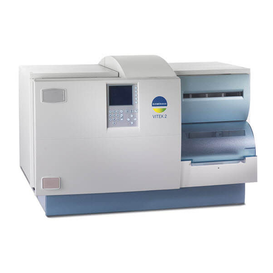
Chapter 2: System Overview Chapter 2: System Overview Preparations For Unpacking the VITEK 2 Smart Carrier Station Figure 2-1 shows a Smart Carrier Station (SCS). Display ar Code Scanner Screen Keyboard Base Unit Figure 2-1 Smart Carrier Station Inspect the shipping container for external damage. If it has been damaged, inspect the SCS itself for damage. -
Page 14: Unpacking Procedure
Unit accepts either 110VAC or 220VAC supply Smart Carrier will sense and determine value supplied voltage and automatically adjust value internally within the power supply. Figure 2-2 SCS – Cable Connections VITEK 2 Smart Carrier Station Service Manual 510747-1 REV. 01/02... - Page 15 5. Once the configuration screen is displayed, set the desired configuration settings. For details on these settings refer to the VITEK 2 User’s Manual. 6. If problems are encountered in setting up the unit, refer to chapter six of this manual for troubleshooting information.
-
Page 16: System Physical And Electrical Requirements
NOTE : Assure that the label shown below is attached to the Base Unit below the Display Screen (see figure 3-1) to remind the user of the (upper) ambient temperature limit (30 ° C or 86 ° F). VITEK 2 Smart Carrier Station Service Manual 510747-1 REV. 01/02... -
Page 17: Chapter 3: System Operation
Chapter 3: System Operation Unit Description The VITEK 2 Smart Carrier Station (SCS) is a dedicated, PC-type computer. Laboratory technicians enter test card and specimen information into the “button” memory of the cassette for transfer to the VITEK 2 instrument. The unit consists of: ♦... -
Page 18: Cassette
Base Unit which connect electrically to the memory when the cassette is placed on the Base Unit. TEST CARD SLOT TEST TUBE HOLDER FOR SPECIMEN Figure 3-2 Cassette – Top View TEST TUBE BUTTON RELEASE MEMORY Figure 3-3 Cassette – Bottom View VITEK 2 Smart Carrier Station Service Manual 510747-1 REV. 01/02... -
Page 19: Base Unit
SCS, the VITEK 2 will read the memory. This non-volatile memory contains the patient, test, and carrier-specific information for the system. After the data has been read by VITEK 2, it tags it as “read” in preparation for the next use of the cassette. -
Page 20: Bar Code Scanner
CODABAR, CODE39, INTERLEAVED 2 of 5, CODE 2 of 5, MATRIX 2 of 5, CODE 11, CODE 93, CODE 128, IATA CODE 2 of 5, Telepen, UPC, EAN/JAN, and PDF 417. VITEK 2 Smart Carrier Station Service Manual 510747-1 REV. 01/02... -
Page 21: Keyboard
The special keys are, from the top: the HELP key and the PREVIOUS/NEXT SLOT key. The HELP key is used to display context-sensitive help that describes the current functions available. (See VITEK 2 User’s Manual for additional information.) VITEK 2 Smart Carrier Station Service Manual... -
Page 22: Display Screen
ENTERS SAMPLE Card DATA. Organism FOR EACH ID, THERE CAN BE A SUSCEPTIBILITY TEST. Ancillary THESE TESTS CAN BE PRE-DILUTED OR AUTOMATIC. Modifier: Dilution mode = Figure 3-7 Data Entry Screen VITEK 2 Smart Carrier Station Service Manual 510747-1 REV. 01/02... -
Page 23: Unit Operation
4. Enter data for the card in the next slot. 5. After all information has been entered, remove the cassette from the SCS and put it into the VITEK 2 instrument for processing. VITEK 2 Smart Carrier Station Service Manual... -
Page 25: Chapter 4: System Components
Chapter 4: System Components Chapter 4: System Components Chapter Four familiarizes the user with the system components of the VITEK 2 Smart Carrier Station (SCS). This chapter provides more detailed descriptions of the individual component parts of each system as listed below: ♦... -
Page 26: Computer Electronics
Board) and the Power Supply. The Contrast Control Assembly is contained in the SCS back cover. DISPLAY ASSEMBLY CONTRAST SCS I/O PCB CONTROL ASSEMBLY POWER ASSEMBLY SUPPLY BOARD KEYBOARD Figure 4-1 Electronic Component Locations VITEK 2 Smart Carrier Station Service Manual 510747-1 REV. 01/02... -
Page 27: Display Assembly
Screen contrast is adjusted by a thumbwheel at the back of the Base Unit. The Display Assembly and flex cable are shown in figures 4-2 and 4-3. Figure 4-2 Display Assembly and Flex Cable VITEK 2 Smart Carrier Station Service Manual 510747-1 REV. 01/02... - Page 28 LCD. The LCD portion of the screen actually darkens the screen to block the backlighting to produce the displayed characters. The LCD is controlled by the CPU/Video Board, which is attached to the I/O PCB Assembly. VITEK 2 Smart Carrier Station Service Manual 510747-1 REV. 01/02...
-
Page 29: Display Interface Board
The board is shown in Figure 4-4. The jumper settings for the board as well as the locations of the connectors and voltage test points are shown in figure 4-5. Figure 4-4 Display Interface PCB VITEK 2 Smart Carrier Station Service Manual 510747-1 REV. 01/02... - Page 30 Chapter 4: System Components Backlight Inverter TP11 TP10 TP13 TP12 Figure 4-5 Display Interface PCB Jumper Settings, Connector and Voltage Test Point Locations VITEK 2 Smart Carrier Station Service Manual 510747-1 REV. 01/02...
-
Page 31: Power Supply Board
Power Entry Assembl Ground Post Harness Harness Figure 4-6 SCS Power Supply VITEK 2 Smart Carrier Station Service Manual 510747-1 REV. 01/02... -
Page 32: Scs Contrast Control Assembly
4-7. Display contrast is adjusted by turning the thumbwheel protruding through the back cover. Speaker Contrast Control Assembly Thumbwheel Figure 4-7 Contrast Control Assembly VITEK 2 Smart Carrier Station Service Manual 510747-1 REV. 01/02... -
Page 33: Scs I/O Board Assembly
DUAL FAN ASSEMBLY BATTERY NOTE: THE SCS I/O BOARD SCS MAIN ASSEMBLY CONSISTS OF VIEW FROM FRONT INTERFACE BOARD THESE TWO BOARDS OF SMART CARRIER Figure 4-9 Base Unit Electronics (Drawing) VITEK 2 Smart Carrier Station Service Manual 510747-1 REV. 01/02... -
Page 34: Cpu/Video Board
Figure 4-10 CPU/Video Board (component side) WARNING! If the CPU/Video Board is removed from the SCS I/O PCB Assembly, the Complementary Metal Oxide Semiconductor (CMOS) setup must be reconfigured. (See Appendix B.) 4-10 VITEK 2 Smart Carrier Station Service Manual 510747-1 REV. 01/02... -
Page 35: Chapter 5: Component Installation
Chapter 5: Component Installation This chapter contains the common field repair procedures for gaining access to the internal components and replacing various defective components of the VITEK 2 Smart Carrier Station. Before performing any of these procedures, be sure you have used the troubleshooting procedures in Chapter Six of this manual to properly isolate the problems. -
Page 36: Voltage Test Points
0 or 5 VDC Display drive; 0 VDC=on, 5 VDC=off -30 VDC +5 VDC +5 VDC TP10 0 VDC TP11 -20 VDC TP12 0 VDC TP13 Display enable signal; Seiko display only VITEK 2 Smart Carrier Station Service Manual 510747-1 REV. 01/02... -
Page 37: Cover Removal And Replacements
9. Unplug the ribbon cable from J1 on the Contrast Control Assembly. 10. Disconnect the speaker at the speaker harness extension connector. (See figure 5-2.) BACK VIEW Figure 5-1 Back Cover Removal VITEK 2 Smart Carrier Station Service Manual 510747-1 REV. 01/02... - Page 38 9. Plug the Bar Code Scanner and the keyboard into the Base Unit. 10. Plug the power cord into the Base Unit. 11. If the unit is to be immediately returned to service, switch the power ON. VITEK 2 Smart Carrier Station Service Manual 510747-1 REV. 01/02...
-
Page 39: Top Cover
3. Attach the four screws (A) through the bottom of the Base Unit. (See figure 5-3.) 4. Perform back cover replacement steps 1-10. 5. If the unit is to be immediately returned to service, switch the power ON. VITEK 2 Smart Carrier Station Service Manual 510747-1 REV. 01/02... -
Page 40: Display Assembly
3. Reconnect the display flex cable to J7 on the SCS Main Interface Board. (See figure 5-2.) 4. Replace the back cover per back cover replacement steps 1-10. 5. If the unit is to be immediately returned to service, switch the power ON. VITEK 2 Smart Carrier Station Service Manual 510747-1 REV. 01/02... -
Page 41: Electrical Component And Circuit Board Replacements
4. Remove the four screws (A) securing the Power Supply Board to the Base Unit. (See figure 5-5.) Power Entry Assembly Ground Post Harness Insulator Harness Figure 5-5 Power Supply Board Removal – Screws and Wiring VITEK 2 Smart Carrier Station Service Manual 510747-1 REV. 01/02... - Page 42 Entry Assembly directly to the chassis. The ground from the switch block must be the only lug connected to the post with only a star washer beneath it. 8. Replace the top cover per the procedure in this chapter. VITEK 2 Smart Carrier Station Service Manual 510747-1 REV. 01/02...
-
Page 43: Scs Contrast Control Assembly
2. Attach the ribbon cable to connector J1 on the Contrast Control Assembly. 3. Replace the Back Cover per the procedure in this chapter. Speaker Contrast Control Assembly Figure 5-6 . Contrast Control Assembly VITEK 2 Smart Carrier Station Service Manual 510747-1 REV. 01/02... -
Page 44: Scs I/O Pcb Assembly
NOTE: Verify that the DC Harness is twisted and routed as shown in figure 5-7, so it does not rest against the DC power supply. 4. Replace the top cover per the procedure in this chapter. 5-10 VITEK 2 Smart Carrier Station Service Manual 510747-1 REV. 01/02... -
Page 45: Replacement Of Dual Fan Assembly
2. Attach the fans with the two screws, flat washers, and lock washers (B) and the single screw, flat washers, lock washer, and nut (C). (Note in figure 5-7 that the VITEK 2 Smart Carrier Station Service Manual 5-11 510747-1 REV. 01/02... -
Page 46: Flex Cable
4. Gently remove the flex cable from J2 of the Display Board and disconnect it from J7 of the Main Interface Board. Figure 5-8 Flex Cable Removal 5-12 VITEK 2 Smart Carrier Station Service Manual 510747-1 REV. 01/02... - Page 47 6. Attach the five screws (B) holding the cover to the housing. (See figure 5-4.) 7. Replace the back cover per the procedure in this chapter. Figure 5-9 Display Cover Replacement VITEK 2 Smart Carrier Station Service Manual 5-13 510747-1 REV. 01/02...
-
Page 48: Display Board
6. Disconnect the two cables from connectors J1 and J3. (See figure 5-10.) 7. Remove the Display Board from the Display Assembly. Backlight Inverter TP11 TP10 TP13 TP12 Figure 5-10 Display Interface PCB Jumper Settings, Connector and Voltage Test Point Locations 5-14 VITEK 2 Smart Carrier Station Service Manual 510747-1 REV. 01/02... - Page 49 7. Attach the five screws (B) holding the cover to the housing. (See figure 5-4.) 8. Replace the Display Assembly per the procedure in this chapter. VITEK 2 Smart Carrier Station Service Manual 5-15 510747-1 REV. 01/02...
-
Page 50: Firmware Update Options
You receive periodic program updates from bioMérieux. The update package includes instructions to update the computer workstation, the VITEK 2 instrument, and the SCS. Prior to updating the SCS, attach the cable 186132-10 from the workstation (tty0) to the SCS. -
Page 51: Chapter 6: Troubleshooting
Chapter 6: Troubleshooting This chapter contains troubleshooting information to be utilized ONLY by an authorized VITEK 2 instrument service representative. All safety and hazard information must be clearly understood and the appropriate safeguards must be exercised anytime the instrument is serviced. -
Page 52: No Data Entry Screen
◊ Rubbing the contacts with a pencil eraser will remove oxidation. ♦ Remove back cover and check the connections and wires between the SCS cassette contacts and J5 on the Main Interface Board. VITEK 2 Smart Carrier Station Service Manual 510747-1 REV. 01/02... -
Page 53: Error Messages
◊ If all voltages are absent or improper, either the DC Harness is not connected correctly or the Power Supply Board is probably defective and in need of replacement. NOTE: Table 5-1, Voltage Test Points, is provided for general reference. VITEK 2 Smart Carrier Station Service Manual 510747-1 REV. 01/02... -
Page 54: Bar Code Scanner Troubleshooting
♦ If the SCS does not operate with the “good” keyboard, the SCS I/O PCB Assembly is defective and must be replaced. ♦ Check to see if the SCS Keyboard Switch is set for “AT.” VITEK 2 Smart Carrier Station Service Manual 510747-1 REV. 01/02... -
Page 55: Display Troubleshooting
◊ If the monitor check reveals a defective CPU/Video Board, replace the SCS I/O PCB Assembly. ◊ If the monitor check indicates the Video Board is working, replace the Display Interface PCB. VITEK 2 Smart Carrier Station Service Manual 510747-1 REV. 01/02... -
Page 56: No Display - No Backlight
♦ If the 5 VDC, -20 VDC, +12 VDC and JP2 and JP6 are reading/set properly, place jumper across pins 1 and 2 of JP1. If the backlight is not working, replace the LCD. If it is working, replace the Display Board. VITEK 2 Smart Carrier Station Service Manual 510747-1 REV. 01/02... -
Page 57: Dual Fan Assembly Troubleshooting
If the fans fail to operate, the suspension temperature inside the cassette test tubes could increase beyond the allowable limit. This could cause the suspension to boil over and possibly cross contaminate after the cassette is placed in the Vitek 2 Instrument under vacuum conditions. -
Page 59: Appendix A: Glossary
Memory location that does not rely on external power to maintain information. BIOS Basic Input/Output System Complementary Metal Oxide Semiconductor CMOS Central Processing Unit Liquid Crystal Display Smart Carrier Station Smart Carrier Station Assembly SCSA VITEK 2 Smart Carrier Station Service Manual 510747-1 REV. 01/02... -
Page 61: Appendix B: Cmos Configuration For The Scs
NONE ATA/IDE Disk 1 NONE ATA/IDE Disk 2 NONE Video EGA/VGA Base Memory Extended Memory 3072 Error Halt NO HALT ON ANY ERRORS Video Shadow Ram ENABLED System POST NORMAL VITEK 2 Smart Carrier Station Service Manual 510747-1 REV. 01/02... - Page 62 64K@D0000 Local Bus Video Display FP & CRT Flat Panel Display Type Video State Enabled Blank POST Test Disabled Serial Boot Loader Disabled Watchdog Timer Disabled Hot Key Setup Enabled VITEK 2 Smart Carrier Station Service Manual 510747-1 REV. 01/02...
- Page 63 AT Bus HDC Disk 1 Hard Drive Not Active Hard Drive Not Active Hard Drive Not Active Hard Drive Not Active Hard Drive Not Active Hard Drive Not Active Hard Drive Not Active VITEK 2 Smart Carrier Station Service Manual 510747-1 REV. 01/02...
- Page 64 “S” key to save the changes. The unit will save the entered settings into CMOS memory and reboot with the new settings. Verify that the unit reboots successfully. VITEK 2 Smart Carrier Station Service Manual 510747-1 REV. 01/02...
-
Page 65: Appendix C: Bar Code Scanner Bar Codes
3800, use the bar codes in figure C-2 to reprogram the Bar Code Scanner. (Scan First) (Scan Second) Figure C-1 Bar Codes for Bar Code Scanner Item Number 722106 VITEK 2 Smart Carrier Station Service Manual 510747-1 REV. 01/02... - Page 66 ~ 0 1 V S U F C R ; D L Y C H R 0 2 . IBM PC AT (Scan Second) Figure C-2: Bar Codes for Bar Code Scanner Item Number 3800 VITEK 2 Smart Carrier Station Service Manual 510747-1 REV. 01/02...
Need help?
Do you have a question about the VITEK 2 and is the answer not in the manual?
Questions and answers