Table of Contents
Advertisement
Quick Links
Advertisement
Table of Contents

Related Manuals for Leader PHABRIX Rx 2000


Summary of Contents for Leader PHABRIX Rx 2000
- Page 1 Rx 2000 User Manual Software Release 9.08 Revision: 11...
-
Page 2: Notice
HDMI ® is the registered trademark of HDMI Licensing and is used within the document for identification purposes only. PHABRIX® Limited Omega House Enterprise Way, Phone: +44 (0)1635 873030 Thatcham, Berkshire RG19 4AE Email: support@phabrix.com United Kingdom Web: https://www.phabrix.com PHABRIX Rx 2000 Page ii User Manual... -
Page 3: Revision
GPIO Loudness Control; Increased Range of Rx Generators’ Master Control. 2020 November 9.08 Vectorscope addition of x2 Gain for CbCr signals; 16:9 mode support for 525-line signals in Picture 2022 scaler; additional bug fixes. PHABRIX Rx 2000 User Manual Page iii... -
Page 4: Getting Started
Getting Started Package Contents The shipping box should include the following: One black carrying bag containing: PHABRIX Rx 2000 unit Power Supply Unit Mains lead Allen key User Manual and Firmware on USB key. Note: Both the latest versions of the user manual and firmware are available from the Software Downloads section of the PHABRIX website: https://www.phabrix.com/support/product-software-downloads/... -
Page 5: Installation Environment
LCD. Do not apply force to the LCD when cleaning or it may be damaged. Warning: Remove the power supply from the unit and turn OFF before cleaning. Do not allow any water or other liquid to enter the unit while cleaning. PHABRIX Rx 2000 User Manual Page v... -
Page 6: Rohs 2 Compliance
RoHS Regulations. Disposal of Equipment This product is subject to the European WEEE (Waste Electrical and Electronic Equipment) directive and should be disposed of according to the regulations of each country. PHABRIX Rx 2000 Page vi User Manual... -
Page 7: Trademarks
Intel and Intel Core are trademarks of Intel Corporation or its subsidiaries. All other trademarks and registered trademarks are of their respective holders. In this user manual, ™ and ® marks are not specified. PHABRIX Rx 2000 User Manual Page vii... -
Page 8: Table Of Contents
Four Channel Closed Caption (Now Included as Standard) 1-14 Front Panel Controls Overview Switching On and Off the Instrument Dual Instrument Display Front Panel Versus HDMI® Monitor Output Control Confidence Display Main Menu Instrument Status PHABRIX Rx 2000 Page viii User Manual... - Page 9 Log Setup 2-90 Log Eye Jitter 2-93 Log ANC Status 2-94 Speaker Menu 2-95 Speaker 2-95 Speaker / Headphone 2-95 Admin Menus 2-97 USB Disk Connected Window 2-97 Monitor Output HDMI Output Overview PHABRIX Rx 2000 User Manual Page ix...
- Page 10 Audio Monitoring Setup 3-88 Dolby Decoder Setup 3-90 Surround Channel Setup 3-91 Time Code Displays 3-91 Default Window Size 3-93 Dolby Generator Setup (Dolby Generator Option) 3-94 Logging Panels 3-100 Overview 3-100 Event Log 3-100 PHABRIX Rx 2000 Page x User Manual...
- Page 11 Front Panel Dimensions Back Panel Dimensions Top Panel Dimensions Side Panel Dimensions Front Panel Front Panel Display Loudspeakers Headphone Output Rx 2000 Rear Panel Power Connection External Locking Reference AES Input SDI Out HDMI Local Control PHABRIX Rx 2000 User Manual Page xi...
- Page 12 AES Audio Input Decoded Dolby Audio (Dolby Decoder Module) Audio Monitoring Speaker / Headphone Audio monitoring Rear Panel Monitoring HDMI Output Monitoring HDMI Over SDI monitoring Audio Routing AES Audio Output Generator SDI Audio Output PHABRIX Rx 2000 Page xii User Manual...
-
Page 13: Description
The Rx platform has been designed to serve the varied test and measurement needs of the broadcast industry. PHABRIX has developed a modular system from which specific broadcast client requirements can be satisfied. PHABRIX Rx 2000 User Manual Page 1-1... - Page 14 Rx 1000 Rasterizer – a compact 1U 19 inch rack-mount chassis with OLED display interface with four Rx module bays. Rx 500 Rasterizer – a compact 1U half-rack width chassis with OLED display interface with two Rx module bays. PHABRIX Rx 2000 Page 1-2 User Manual...
-
Page 15: Description
Analyzer or Generator modules. See the “Modules” section for details of the different module types. The power for the Rx instrument is provided by a separate PSU unit that connects to the 4-pin male XLR connector at the left of the instrument. PHABRIX Rx 2000 User Manual Page 1-3... -
Page 16: Specifications
Specifications See the Appendix "Specifications" on page B-1 for specification details. PHABRIX Rx 2000 Page 1-4 User Manual... -
Page 17: Rx Modules
Are standard USB 2 connections provided for connection of a keyboard and mouse to con- trol the HDMI® monitor output. LAN: 10 / 100-base-T connection allowing the Rx instrument to be connected into a network and accessed over TCP/IP so that it can be controlled remotely. PHABRIX Rx 2000 User Manual Page 1-5... -
Page 18: Single Analyzer, Dual Input Module
Link 2 signal must be connected to IN2 BNC connector on the same Analyzer module. Likewise if Fiber is being used Link 1 should connect to OPTICAL A and Link 2 should connect to OPTICAL B . PHABRIX Rx 2000 Page 1-6 User Manual... -
Page 19: Single Analyzer, Single Generator Module
Single Analyzer, Single Generator, Physical Layer Measurement Module The PHRXM-AGE module allows a single connected SDI or Optical video signal to be monitored continuously and allows the generation of a single SDI or Optical video test signal. PHABRIX Rx 2000 User Manual Page 1-7... -
Page 20: Dual Output Generator Module
GEN B output. Likewise if a Fiber connection is being used the Link 1 signal is produced on OPTICAL GEN A and the Link 2 signal is produced on OPTICAL GEN B. PHABRIX Rx 2000 Page 1-8... -
Page 21: Rx Software Options
DC offset, the EQ part of the pattern inverts a bit at the start of the first line in each alternate frame. This is the form of 3G Level B Pathological signal that many video manufacturers are adopting as their test signal of choice as it stresses electronic circuits more thoroughly. PHABRIX Rx 2000 User Manual Page 1-9... -
Page 22: Sdi Data Display And Ancillary Packet Analysis
Ancillary Status Allows additional user-defined selections with the appropriate DID or SDID code. Access to the SDI analysis functionality is via the Analyzer - Data View and Sig Info - ANC Inspector menus. PHABRIX Rx 2000 Page 1-10 User Manual... -
Page 23: Advanced Physical Layer Analysis
By analyzing jitter in this detailed way an engineer can determine whether a sig- nal is in or out of specification and also get a feel for where any problems lie. Note: Now included with purchase of Analyzer Eye Module (PHRXM-AE or PHRXM-AGE). PHABRIX Rx 2000 User Manual Page 1-11... -
Page 24: Enhanced Remote Control (Now Included As Standard)
The option provides a programming guide including command information and examples, and can be downloaded from the PHABRIX website. A Windows™ application for testing the interface is also provided as part of this option. See the Remote Control Guide for details. PHABRIX Rx 2000 Page 1-12 User Manual... -
Page 25: Dolby Metadata Generator
SDI video stream. The Dolby audio may be monitored from any of the SDI input embedded audio channel pairs or AES input. Peak metadata audio levels metering is also displayed for Dolby E. PHABRIX Rx 2000 User Manual Page 1-13... -
Page 26: Four Channel Loudness (Now Included As Standard)
This option (PHRXO-4CAP) allows up to four channels of closed caption to be displayed. This is allocated as one channel per analyzer module. This supports WTS/OP42/OP47, EIA 608 and EIA 708 closed caption / subtitle formats. > PHABRIX Rx 2000 Page 1-14 User Manual... -
Page 27: Front Panel Controls
Switching On and Off the Instrument To turn on your PHABRIX Rx 2000 press the red button at the top right-hand corner of the front panel. Once the system has started, pressing the button again will switch it off. If for some reason the instrument stops responding, press and hold the button for a few seconds to switch it off. -
Page 28: Confidence Display
Dual instrument display on the front panel is available for the Rx 2000. Selecting the View button on the left-hand display will show a bank of instruments views available for selection. Select the None button to clear the display. PHABRIX Rx 2000 Page 2-2 User Manual... -
Page 29: Main Menu
When in a specific function e.g., Generator, Analyzer etc., the cursor controls on the right- hand of the instrument select a field to edit. The current field has a red box around it. Pressing the OK button PHABRIX Rx 2000 User Manual... - Page 30 Allows the setup of system wide settings including memories, date/time and software. Logging Selects the logging page to view and setup the error logging system. Speaker Selects the speaker / headphone setup page. PHABRIX Rx 2000 Page 2-4 User Manual...
-
Page 31: Multiple Analyzers
Link 2 signal must be connected to IN2 BNC connector on the same Analyzer module. Likewise, if Fiber is being used, Link 1 should connect to OPTICAL A and Link 2 should connect to OPTICAL B. PHABRIX Rx 2000 User Manual Page 2-5... -
Page 32: Generator Menus
SD/HD vide or 3G level A or level B video. Dual streams refer to the ability of the Rx instrument to generate two separate pictures when transmitting 3G-level B in some formats. Which mode is selected determines which formats are available. Only valid frame rates for the output standard may be selected. PHABRIX Rx 2000 Page 2-6 User Manual... - Page 33 Cyan (0% R, 100% G, 100% B) Green (0% R, 100G, 0% B) Magenta (100% R, 0%G, 100% B) Red (100% R, 0% G, 0%B) Blue (0% R, 0% G, 100% B) Black (0% R, 0% G, 0% B) PHABRIX Rx 2000 User Manual Page 2-7...
- Page 34 The SMPTE Color bars test pattern was developed for the NTSC analog video standard and produced by using the combinations of the Red, Green and Blue primary colors as used in 75% color bars. PHABRIX Rx 2000 Page 2-8 User Manual...
- Page 35 The Luma Ramp test pattern is used to check the linearity of the luminance component. This test pattern exercises all of the discrete digital video levels including illegal values below video black and above peak white. PHABRIX Rx 2000 User Manual Page 2-9...
- Page 36 The Gray Bar - 11 - Vertical test pattern is used to check for differential gain distortion in the luminance component line by line. The bars range from 100% white to 0% black in 10% steps. PHABRIX Rx 2000 Page 2-10...
- Page 37 Any of the preset zone plates may be copied to the custom zone plates to act as a starting point for a new zone plate. As the zone plate settings are stored in user memories several custom zone plates are available: PHABRIX Rx 2000 User Manual Page 2-11...
- Page 38 It is specified in degrees per frame. Angle Changes the angle of the zone plate and thus can change a horizontal sweep into a ver- tical sweep or rotate an elliptical zone plate pattern. XScale/Start Freq PHABRIX Rx 2000 Page 2-12 User Manual...
- Page 39 In SD there is one EDH ancillary packet per field. When errors are being inserted every EDH value gets deliberately corrupted. This creates one error count per field. (Actually one AP error and one FF error). In HD there is a PHABRIX Rx 2000 User Manual Page 2-13...
- Page 40 When editing text, the keyboard above is displayed to allow easy editing. Move the cursor to select the key to press and then press Ok to select. The Shift menu key causes the next keyboard to change to shift mode for the next key press. PHABRIX Rx 2000 Page 2-14 User Manual...
- Page 41 Note: The Generator video format and frame rate will automatically be set to that of the video clip being played. Note: Box and Ident cannot be used when a video clip is selected for playout. PHABRIX Rx 2000 User Manual Page 2-15...
-
Page 42: Genlock Menu
The dropdown menu allows the selection of the system locking reference. This can be the external locking reference signal or one of the SDI inputs. The System Reference defines the video source that the Rx system is synchronized to and affects all of the Rx outputs: PHABRIX Rx 2000 Page 2-16 User Manual... - Page 43 This mode of operation may produce out of specification jitter. Free Run should be used when using Analyzer / Generator modules to perform closed-loop testing, especially if Eye and Jitter measurements are being made. PHABRIX Rx 2000 User Manual Page 2-17...
-
Page 44: Audio Group Menu
If the Dolby Generation option has been purchased, the source may be set to DolbyGen at which time the other channel in the audio pair is also set to DolbyGen and gain control PHABRIX Rx 2000 Page 2-18 User Manual... - Page 45 −18 and −24 dBFS. This feature allows all embedded outputs to be adjusted together as well as giving a simple method to change from −18dB to −24dB based standard levels. PHABRIX Rx 2000 User Manual Page 2-19...
-
Page 46: Dolby (Dolby Metadata Generator Option)
Involves five channels for normal-range speakers (20 Hz – 20,000 Hz) (right front, center, left front, rear right, rear left) and one channel (20 Hz – 120 Hz allotted audio) for the sub- woofer driven low-frequency effects. Dolby 7.1 PHABRIX Rx 2000 Page 2-20 User Manual... - Page 47 1080p29, 720p29, 1080i59, 525i59(NTSC) – due to length of packet being over one frame long 1080p50 1080p25, 720p25, 1080i50, 625i50(PAL) – due to length of packet being over one frame long 1080p59 1080p29, 720p29, 1080i59, 525i59(NTSC) – due to length of packet being PHABRIX Rx 2000 User Manual Page 2-21...
- Page 48 If this checkbox is checked, the line number displayed is relative to the Dolby specified ideal line. A value of 0, therefore, starts the Dolby-E packet on the Ideal Line for that video format. PHABRIX Rx 2000 Page 2-22 User Manual...
- Page 49 Dolby 7.1 Dependent Substream. LR CtrDnMix: (Left, right, center down-mix) is a weighting value used in the encoding and decoding of surround sound mixes for a Dolby 5.1 Independent Substream. PHABRIX Rx 2000 User Manual Page 2-23...
- Page 50 The Surround Channel 3 dB Attenuation function is used to apply a 3 dB attenuation to the Surround channels of a multichannel soundtrack created in a room with film style cal- ibration, when encoding it for consumer home theater playback. Sur Ph+Filter PHABRIX Rx 2000 Page 2-24 User Manual...
- Page 51 Note: If DolbyGen is selected as the Source for any AES output, the Dolby Generator in the System menu needs to be set to External reference otherwise the Dolby audio packet may not be embedded into the AES stream in the correct place. PHABRIX Rx 2000 User Manual Page 2-25...
-
Page 52: Analyzer Menus
Signal Data page, the cursor will show where that is on the ‘Full Picture’ page. The different types of analyzer can be displayed on the front panel of the Rx 2000 instrument and as window panels on the HDMI® monitor output. PHABRIX Rx 2000 Page 2-26 User Manual... -
Page 53: Picture
If the closed caption option is installed, the Caption Options menu allows the selection of WST, OP42, OP47, EIA 608 and EIA 708 subtitles. The corresponding closed caption can be selected from the Closed Caption setup menu by to the right of the Caption checkbox. PHABRIX Rx 2000 User Manual Page 2-27... - Page 54 Moving the cursor into the VANC region reveals any ancillary data present there as if it were picture data. The specific packet data words present can be inspected closely with the SDI data option toolset (PHRXO-DATA). PHABRIX Rx 2000 Page 2-28 User Manual...
- Page 55 100% amplitude or if they go below 0% (absolute black). These are represented by the values Hi 940 decimal, 700 mV or 100% and Lo 64 decimal, 0 mV or 0% in the Gamut setup menu. PHABRIX Rx 2000 User Manual...
- Page 56 Manual trigger for video clip capture ( T ) Start record buffer ( ● ) Step backward through the captured video clip frame-by-frame ( < ) Stop playing the captured video clip ( ■ ) PHABRIX Rx 2000 Page 2-30 User Manual...
- Page 57 ANC C2 – will trigger when the link 2 chroma ANC stream checksum error flag is set. The Pos value is used to position the trigger point in the required position within the rolling record buffer to select the proportion of frames before and after the trigger point. PHABRIX Rx 2000 User Manual Page 2-31...
- Page 58 Allows the currently selected video clip in the dropdown list to be deleted. The current progress of the Save or Load operation is displayed in the Progress thermometer. Note: Video clips can be exported and imported using the USB copy menu. PHABRIX Rx 2000 Page 2-32 User Manual...
-
Page 59: Data View
HBL - Horizontal blanking Comp: Similar to the Strm mode above but in a component mode with Cr and Cb in different columns. See Strm mode above for a description of the info column. Split: PHABRIX Rx 2000 User Manual Page 2-33... - Page 60 10 bit values across the different streams and thus will give unfamiliar values. When the UnPack checkbox is checked the values in the active picture are unpacked to RGB or YCbCr values. PHABRIX Rx 2000 Page 2-34 User Manual...
-
Page 61: Waveform Monitor
Only the red channel is shown. Green: Only the green channel is shown. Blue: Only the blue channel is shown. RGB: The Red, Green and Blue waveforms are shown as three separate waveforms in a Parade format. RGBOvr: PHABRIX Rx 2000 User Manual Page 2-35... - Page 62 The timing measurements may be set in either pixels or micro-seconds (μs) Cursors Various cursor modes are available on the Waveform monitor: Pict: This makes the picture cursor visible. The picture cursor can be moved as required. Ampl PHABRIX Rx 2000 Page 2-36 User Manual...
- Page 63 Holding down the x10 and x100 buttons while pressing the Up and Down cursor buttons increases the speed of the cursor. PHABRIX Rx 2000 User Manual Page 2-37...
-
Page 64: Vectorscope
When Zoom is set to x1, this function enables you to set the gain of the vectorscope display to x2. If Zoom is set to anything other than x1, the Gain control is grayed-out. PHABRIX Rx 2000 Page 2-38 User Manual... -
Page 65: Eye And Jitter
Data dependent jitter due to the actual data content that, even after randomization, that con- tains sequences of zeros long enough for the clock regeneration to loose phase lock. PHABRIX Rx 2000 User Manual Page 2-39... - Page 66 20% and 80% points on the eye waveform. Rise/fall difference - measured in picoseconds Rising edge overshoot – measured as a percentage of the overall signal amplitude. Falling edge overshoot – measured as a percentage of the overall signal amplitude. PHABRIX Rx 2000 Page 2-40 User Manual...
- Page 67 −3 dB at 9.5 MHz low −3 dB at 4.75 MHz low −3 dB at 0.86 MHz low pass pass pass On screen horizontal cursors indicate where on the eye the rise time measurements are being made. PHABRIX Rx 2000 User Manual Page 2-41...
- Page 68 Note that he time histogram overlays some of the automatic measurement display. The measurements may still be read by Remote Control if purchased. PHABRIX Rx 2000 Page 2-42 User Manual...
- Page 69 This button clears the eye display. It is only enabled when the update mode is set to infinite update mode. Eyes: Adjusts the number of eyes visible on the eye display. The 10 and 20 modes are useful for observing serial-parallel conversion jitter. PHABRIX Rx 2000 User Manual Page 2-43...
-
Page 70: Jitter Analysis
It is only enabled when the update mode is set to infinite update mode. Clear: This button clears the eye display. It is only enabled when the update mode is set to infinite update mode. PHABRIX Rx 2000 Page 2-44 User Manual... -
Page 71: Signal Information Menus
Signal Information Menus Overview These Signal Info pages give a detailed view of the status of the input (or generator output) signal, subdivided into the following areas: Video status Misc status Ancillary (ANC) status. PHABRIX Rx 2000 User Manual Page 2-45... -
Page 72: Video Status
Under normal conditions, the EDH-AP values should be constant, the full-field values may change if audio or other ancillary data is embedded in the SDI signal. The EDH flags for active picture, full-field and ancillary data are also displayed for diagnostic purposes: PHABRIX Rx 2000 Page 2-46 User Manual... - Page 73 10-bit virtual interfaces and will therefore generate different values from those for YCC422-10. See the Active Picture CRC Technical Information section at the end of the manual for details of CRC calculation. PHABRIX Rx 2000 User Manual Page 2-47...
-
Page 74: Misc Status
The input status on the top line will display Invalid but the values in this section will be updated every few seconds. The Re-sync counter displays the number of times the SDI data has been re-synchronized and can help detect intermittent SDI signal problems. PHABRIX Rx 2000 Page 2-48 User Manual... -
Page 75: Video Input Timing
This can lead to different values to other test and measurement instruments that include an SD (PAL/NTSC) offset in their calculations. By comparing line 1 timings, the Rx instrument can be used to measure time delays accurately through up/down/cross converters. PHABRIX Rx 2000 User Manual Page 2-49... -
Page 76: Anc Status
The SMPTE RP165-EDH packet containing EDH (error data handling) and CRC (cyclic redundancy counts). This only appears on SD-SDI signals. S272-SD Audio: The SMPTE 291M defined SD audio data in HANC space. S272-SD Aux: PHABRIX Rx 2000 Page 2-50 User Manual... - Page 77 RP215 – Film: The SMPTE defined recommended practice data packet for film codes in VANC space. EIA-708 Caption: The EIA standard defined closed caption data for HD-SDI in VANC space. EIA-608 Caption: PHABRIX Rx 2000 User Manual Page 2-51...
- Page 78 The SMPTE defined recommended practice Vertical Timecode data packet in VANC space. RDD8-WSS: The SMPTE defined wide screen switching data packet in the VANC space. S12M-2 V-Tcode: The SMPTE S12M defined standardized frame timecode data packet in VANC space. PHABRIX Rx 2000 Page 2-52 User Manual...
- Page 79 A user-defined data packet used to mark other data packets for deletion (ie to be ignored by down-stream processes. User-1: A user-defined data packet. User-2: A user-defined data packet. User-3: A user-defined data packet. PHABRIX Rx 2000 User Manual Page 2-53...
-
Page 80: Anc Inspector (Sdi Analysis Option)
This may be: C: Checksum Error D: DBN (Data block number) Error P: Parity Error G: ANC Gap Error Several of the above flags may be displayed at the same time. PHABRIX Rx 2000 Page 2-54 User Manual... - Page 81 HANC/VANC Filter: A filter for simpler selection of where to search for packets. It may be selected to search the HANC (Horizontal Ancillary Data) area, the VANC (Vertical Ancillary Data) area or both areas. PHABRIX Rx 2000 User Manual Page 2-55...
- Page 82 The Setup dialog also shows when an ANC packet has been detected and where it was found. This makes changing a filter simpler as the effect of the filter can be determined without closing the dialog. This dialog also allows the user-defined ANC packets to be configured. PHABRIX Rx 2000 Page 2-56 User Manual...
-
Page 83: Sfp Info
The SFP Info menu displays details of the currently installed SFP module. Along with manufacturer’s details of the SFP parameters, this displays the transmitted and received power which can indicate optical losses in the infrastructure (optical fiber type, distance and connection quality.) PHABRIX Rx 2000 User Manual Page 2-57... -
Page 84: Audio Menus
The source for each pair of audio meters can be selected from the dropdown lists for each pair. The scale and peak program meter ballistics can also be selected from the dropdown menus. PHABRIX Rx 2000 Page 2-58 User Manual... - Page 85 If the metadata Dolby analyzer option is installed, the meters may be set to display the encoded Dolby metadata levels for up to eight Dolby channels within the specified embedded audio pair or PHABRIX Rx 2000 User Manual Page 2-59...
- Page 86 Dolby audio channels. With Decoder 1 or 2 selected, the meter display changes color to blue indicating that decoded Dolby audio is in use and channels can be selected as part of a downmix. PHABRIX Rx 2000 Page 2-60 User Manual...
-
Page 87: Audio Status
Using the Rx 2000 front panel, the Audio Status menu can be displayed by selecting the corresponding Audio button. The Audio Status menu shows the Channel Status for the selected audio channel is displayed in decoded form as well as a hexadecimal dump of the bytes. PHABRIX Rx 2000 User Manual Page 2-61... -
Page 88: Dolby Status (Dolby Analyzer Option)
8 channels of audio (mono, stereo, 5.1 or 7.1) that for a primary program (Programme 1) and optional ancillary programs. These 8 channels are compressed (loss-less) into a digital stream that can be transferred between compatible devices and stored on a standard stereo pair of audio tracks. PHABRIX Rx 2000 Page 2-62 User Manual... - Page 89 This can be done from the Ref menu on the HDMI task bar, the Rx 2000 Dolby Metadata and the Rx 2000 Generator - Genlock menus. PHABRIX Rx 2000 User Manual...
- Page 90 Note: If Dolby E is present on a fast frame rate signal (50p, 59p or 60p) then it should always be referenced to a interlaced reference at the same field rate as the packet length is longer than a single frame and must start at the beginning of an even numbered frame. PHABRIX Rx 2000 Page 2-64 User Manual...
- Page 91 Main (CM) is the normal mode of operation and contains a complete audio program includ- ing dialog, music, and effects. Ctr DnMix: (Center down-mix) is a weighting value used in the encoding and decoding of surround sound mixes for a Dolby 5.1 Independent Substream. Sur DnMix: PHABRIX Rx 2000 User Manual Page 2-65...
- Page 92 Dolby 5.1. The extra surround channel of the Dolby Surround Ex system is matrix-encoded onto the discrete left-surround and right-surround channels of the 5.1 mix. The following control bits can also be set: The LFE Channel parameter enables or disables the Low-Frequency Effects (LFE) channel. PHABRIX Rx 2000 Page 2-66 User Manual...
- Page 93 Dolby E signal. Note also that the LFE channel audio levels do not seem to be metered by current Dolby encoding modules. See the logging section for details on which changes of Dolby E status may be logged. PHABRIX Rx 2000 User Manual Page 2-67...
-
Page 94: Loudness Meters
30 minute intervals are more practical. These logs will be individual, time-stamped CSV (comma separated value) files which are held in the loudness folder within the Rx operating system. (See the section "Rx File Structure" on page C-5 for details). PHABRIX Rx 2000 Page 2-68 User Manual... - Page 95 The Audio and dBFS dropdowns in the Scales section allows the scales of the audio channel meters to be selected. The actual scale of the Loudness meter is defined by the loudness mode selection. PHABRIX Rx 2000 User Manual Page 2-69...
- Page 96 While Loudness GPIO Control is enabled, the two buttons which allow the user to start, stop, pause, resume and reset Loudness in the GUI are hidden and replaced by the GPI Control state. PHABRIX Rx 2000 Page 2-70 User Manual...
- Page 97 It is possible to enable GPIO control for both Presets and Loudness at the same time but, on experiencing a conflicting setting, the system displays an error dialog stating that the current configuration is invalid: PHABRIX Rx 2000 User Manual Page 2-71...
- Page 98 20 second duration. This should give the following results: M, S, I = -23.0 ±0.1 LUFS or M, S, I = 0.0 ±0.1 LU PHABRIX Rx 2000 Page 2-72 User Manual...
-
Page 99: Dolby Decoder Setup (Option)
Dolby channels, pairs of channels or a mixed-down version can be selected. Note: The Dolby Decoder settings are stored as part of the system configuration and cannot be saved in presets. PHABRIX Rx 2000 User Manual Page 2-73... -
Page 100: System Menus
Up / Down cursor keys to select the memory and then press OK. The name edit field next to the memory list will be updated with the name of the selected memory. PHABRIX Rx 2000 Page 2-74 User Manual... - Page 101 Exported memories are in a text format and so may be edited on a PC and downloaded to or from the backups directory on the Rx instrument using FTP or USB. PHABRIX Rx 2000 User Manual Page 2-75...
- Page 102 Locate the next Rx instrument onto which to import the presets and insert the USB pen drive into one of the available USB ports. Again the USB Disk Connected dialog is automatically displayed. From the Types dropdown menu, select: Archives. PHABRIX Rx 2000 Page 2-76 User Manual...
- Page 103 Once the presets file(s) are loaded onto the new Rx instrument, they can be used as previously described in this section. Disk Space The disk space section shows total size of the internal flash disk, how much is used as a percentage and how much free space is available. PHABRIX Rx 2000 User Manual Page 2-77...
-
Page 104: Network
DHCP checkbox is enabled, you will not be able to change these values. Once the network addressing has been setup, select the Apply button to attach the Rx instrument to the network. PHABRIX Rx 2000 Page 2-78... - Page 105 The Rx instrument uses a default Port Number of 2100 for remote control access (see the Remote Control SDK documentation available from the Download section of PHABRIX website.) This port number may now be changed if it conflicts with other applications in your system. PHABRIX Rx 2000 User Manual Page 2-79...
-
Page 106: Info
The Date and Time Setup window allows the selection of Network Time Protocol to control the Rx system time. Select the Set TIme Automatically checkbox and enter primary and secondary addresses for the network time then select the Apply button to apply these changes. PHABRIX Rx 2000 Page 2-80 User Manual... - Page 107 Once a valid new code has been entered, the list of options provided by that code will be displayed. The options code is stored independently to memories and system settings. PHABRIX Rx 2000 User Manual Page 2-81...
-
Page 108: Utils
Displays the hardware details of the CPU Board. Board 1: Displays the hardware details of the Module fitted in chassis slot. 1. Board 2: Displays the hardware details of the Module fitted in chassis slot 2. Board 3: PHABRIX Rx 2000 Page 2-82 User Manual... - Page 109 This section of the menu displays the type of SFP (Small Form Factor Package) module is installed in the board currently selected board in the Board section of the menu. This information is provided for diagnostics purposes only. PHABRIX Rx 2000 User Manual Page 2-83...
-
Page 110: Engineer
Pressing the Download button will cause the current release of software to be downloaded from the Phabrix website. This will take a short time dependent on the connection to the Internet. Once the download has PHABRIX Rx 2000 Page 2-84 User Manual... - Page 111 They can be restored from the System → Memories page using the Restore button and selecting the archive: _Before_Upgrade. The software release notes can be viewed by selecting the Changes button. PHABRIX Rx 2000 User Manual Page 2-85...
-
Page 112: Hdmi/Sdi Output
HDMI output. The HDMI standard and frame rate combo-boxes will be limited to 1080p 50 / 59 / 60. If the HDMI output is disabled, the SDI output may be any frame rate. PHABRIX Rx 2000 Page 2-86 User Manual... - Page 113 When there is no relationship between the frame rate of the locking reference and that of the generated frame rate (for example a 625/50 locking reference and a 23.98 generated test pattern) then there will be a static lock between them but this will not be consistent. PHABRIX Rx 2000 User Manual Page 2-87...
-
Page 114: Logging Menus
Rx instrument can be connected to that source and can be left for several days to log any errors. At the end of that period the log can be examined and the time and date of each error noted. PHABRIX Rx 2000 Page 2-88 User Manual... -
Page 115: Event Log
Note: The event log displays changes in status only, so if the input is always in error and never good, an event will not be shown. To get the full state of the instrument take a look at the current status together with the event log. PHABRIX Rx 2000 User Manual Page 2-89... -
Page 116: Log Setup
If the number of lines changes or line length changes during a frame, the input video will be detected as the TRS changing and an event logged. If the signal stays changing only a PHABRIX Rx 2000 Page 2-90 User Manual... - Page 117 Will log any changed program metadata. This can be useful for following changes to a pro- gram stream over a long period of transmission. Logging This section controls all logging events Clear Clears all entries in the event log. Enable PHABRIX Rx 2000 User Manual Page 2-91...
- Page 118 The specified times must be after the current time. Un- check the box to log at all times. Logging must be enabled using the checkbox above for this to work. PHABRIX Rx 2000 Page 2-92...
-
Page 119: Log Eye Jitter
Eye measurements are performed using statistical calculations on the waveforms and are thus performed at a slower rate than jitter measurements. Measurements can take a few seconds to stabilize and this should be taken into account. PHABRIX Rx 2000 User Manual Page 2-93... -
Page 120: Log Anc Status
This allows the user to define and name their own DID/SDID values for an ANC packet type. Reset Clears the state for all packet types and thus a packet that was displayed as previously in error is shown as OK. PHABRIX Rx 2000 Page 2-94 User Manual... -
Page 121: Speaker Menu
Rx unit. If the checkbox is not enabled the analog audio level will remain the same regardless of the front panel volume control. PHABRIX Rx 2000 User Manual... - Page 122 The Analyzer Source is used to select the specific channels that is to be routed through to rear panel and HDMI audio. The HDMI/SDI 8ch Output checkbox, if enabled, allows eight audio channels to be routed to the rear panel / HDMI audio instead of a stereo pair. PHABRIX Rx 2000 Page 2-96 User Manual...
-
Page 123: Admin Menus
Files can be deleted from either the USB root directory or the currently selected Rx folder using the two delete buttons: <− Delete Permanently deletes the selected / highlighted file in the USB root directory. Delete −> Permanently deletes the selected / highlighted file in the USB root directory. PHABRIX Rx 2000 User Manual Page 2-97... - Page 124 Before the USB pen drive is removed from the Rx unit, select the Eject button to close the session. This will prevent accidental damage or corruption of the files on the USB pen drive. PHABRIX Rx 2000 Page 2-98 User Manual...
-
Page 125: Monitor Output
Analyzer or Generator resource have the same color coding. Clicking on the Input of an Analyzer module will allow different analyzer instrument windows to be selected for that input. Clicking on the Output of a Generator module will allow different generator PHABRIX Rx 2000 User Manual Page 3-1... -
Page 126: Display Area
Vertical Interval Timecode (VITC) and Longitudinal Timecode (LTC) present on the analog (625i/50 and 525i/59.94) locking reference signal connected to the REF connector on the rear of the Rx unit can be displayed on the Task Bar of the HDMI® monitor output. PHABRIX Rx 2000 Page 3-2 User Manual... -
Page 127: Managing The Monitor Output
When the Rx instrument contains multiple Generator modules, the generator to be controlled can be selected from the dropdown list in the corner of the panel (GEN1, GEN2, etc). Note that the module PHABRIX Rx 2000 User Manual Page 3-3... -
Page 128: Contextual Menus
Rx instrument. Contextual Menus Right-clicking on the Picture, Waveform, Vectorscope, Lissajous, Eye and Jitter windows will display context sensitive menus that can be used to control the functions of these instruments. PHABRIX Rx 2000 Page 3-4 User Manual... -
Page 129: Instrument Panel Resizing
To create 3/4 size Picture and Waveform, start with a 1/4 size window and drag the bottom right corner of the window until it is approximately 3/4 size then release. PHABRIX Rx 2000 User Manual Page 3-5... -
Page 130: Generator Panels
Clicking on the Output of a Generator module will allow different generator windows to be displayed for that output. Clicking on instrument type title (Generator, Generator Audio 1-4, Generator Audio 5-8, Generator Reference) allows the generator type to be changed. PHABRIX Rx 2000 Page 3-6 User Manual... -
Page 131: Generator Video
The following color modes may be selected dependent on line standard selected: YCbCr 422 10 bit YCbCr 444 12 bit YCbCr 444 10 bit YCbCrA 4444 10 bit PHABRIX Rx 2000 User Manual Page 3-7... -
Page 132: Pattern
Blue (0% R, 0% G, 100% B) Black (0% R, 0% G, 0% B) The 75% Color bars and 75% Color bars + Red test patterns are produced by using combinations of the Red, Green and Blue primary colors: PHABRIX Rx 2000 Page 3-8 User Manual... - Page 133 This animated test pattern provides a constantly moving Clapper board and corresponding A/V Delay tone when the clapper board reaches the center of the test pattern. For more information, see "A/V Delay Using the Generator (Option: PHRXO-AVD)" on page 3-15 PHABRIX Rx 2000 User Manual Page 3-9...
- Page 134 The Valid Ramp test pattern is used to check the linearity of the Y (luminance), Cr (R-Y) and Cb (B-Y) components. This test pattern exercises all of the discrete digital video levels of these components, excluding illegal values. PHABRIX Rx 2000 Page 3-10 User Manual...
- Page 135 The Color Field test patterns are used to provide primary colors (such as 100% red, green, blue, cyan, magenta and yellow) and monochrome luminance levels to check for calibration and banding effects caused by encoding / decoding processes. PHABRIX Rx 2000 User Manual Page 3-11...
- Page 136 A static zone plate centered on the screen from DC to the Nyquist frequency at left/right edges. Static Zone-2V: A static zone plate centered on the screen from DC to the Nyquist frequency at top/bottom edges. Sweep-Horiz: A horizontal sweep from DC to Nyquist frequency horizontally. Sweep-Vert: PHABRIX Rx 2000 Page 3-12 User Manual...
- Page 137 Sets the vertical scale of grating patterns or the end value of the zone plate sweep fre- quency. The Pathological test patterns are used to check that the phase-locked loop circuitry used to decode SDI data can recover/regenerate the SDI sample clock under worst-case conditions. PHABRIX Rx 2000 User Manual Page 3-13...
- Page 138 Edit button to display the Ident dialog. An overview of the Ident is displayed beside the Edit button. PHABRIX Rx 2000 Page 3-14 User Manual...
- Page 139 +/− 40 frames can be applied in increments of one frame. The AV Delay audio pulse can be inserted on up to 16 embedded SDI audio channels, which can be analyzed simultaneously. PHABRIX Rx 2000 User Manual Page 3-15...
- Page 140 Each Generator module within the system can play-out a video clip captured and saved using the Picture Frame Grab function. This can be used to playout generated test clips as well as video clips captured when an error condition occurred. PHABRIX Rx 2000 Page 3-16 User Manual...
- Page 141 Note: The Generator video format and frame rate will automatically be set to that of the video clip being played. Note: The Box and Ident functions cannot be used when a video clip is selected for playout. PHABRIX Rx 2000 User Manual Page 3-17...
-
Page 142: Generator Reference
Bi-Level / Tri-Level sync or may be locked to the video input. Alternatively, the generator may free run. Delay The test patterns generated by the Generator module can be delayed or advanced with respect to the locking reference input using the Lines and Pixel values. PHABRIX Rx 2000 Page 3-18 User Manual... -
Page 143: Generator Output Audio Menu
DolbyGen and gain control dis- abled. The generated Dolby metadata is defined in the System - Dolby Generator menu. DolbyDecode1: PHABRIX Rx 2000 User Manual Page 3-19... - Page 144 The PHRXM-4AGE module has four bi-directional AES digital audio pairs (IO_A, IO_B, IO_C and IO_ When configured as inputs this allows the audio pairs to be routed to the Audio Meter, Lissajous and Loudness instruments for the 4AES module. PHABRIX Rx 2000 Page 3-20 User Manual...
- Page 145 Note: If DolbyGen is selected as the Source for any AES output, the Dolby Generator in the System menu needs to be set to External reference otherwise the Dolby audio packet may not be embedded into the AES stream in the correct place. PHABRIX Rx 2000 User Manual Page 3-21...
-
Page 146: Analyzer Panels
The 4AES module provides audio-only analysis tools and audio-only generation tools. Pressing the left-hand AES button (input) will display the analyzer functions that are available and pressing on the right-hand AES button (output) will display the Output audio configuration menu. PHABRIX Rx 2000 Page 3-22 User Manual... -
Page 147: Picture
HD signals are always set to an aspect ratio of 16:9. Right-clicking with the mouse in the image area will display contextual menus that can be used to select and setup the different functions on the Picture window. PHABRIX Rx 2000 User Manual Page 3-23... - Page 148 (Interlaced formats only.) This control selects the field for analysis. If the current line is in Field 1, changing the field will change to the same line in Field 2. The field number will change to show the correct field for the current line number. PHABRIX Rx 2000 Page 3-24 User Manual...
- Page 149 Clicking and dragging on the image will move the zoomed image. Closed Caption / Subtitle Display If the closed caption option is installed, the Caption Options menu allows the selection of the following subtitle formats: OP42 OP47 EIA 608 EIA 706 PHABRIX Rx 2000 User Manual Page 3-25...
- Page 150 HD/SD-SDI Data Analyzer and Ancillary Packet Analyzer option) will show IEA 608, IEA 708 and OP47 data packets that appear in the vertical ancillary area of the SDI framework. The corresponding closed caption can then be selected from the Captions setup menu: PHABRIX Rx 2000 Page 3-26 User Manual...
- Page 151 100% amplitude or if they go below 0% (absolute black). These are represented by the values Hi 940 decimal, 700 mV or 100% and Lo 64 decimal, 0 mV or 0% in the Gamut setup menu. PHABRIX Rx 2000 User Manual...
- Page 152 When expanded it will cover the underlying instruments and when it is reduced the underlying instruments will be displayed. The Picture can also be displayed at 3/4 screen size by dragging the bottom right corner of a 1/16 or 1/4 Picture. PHABRIX Rx 2000 Page 3-28 User Manual...
- Page 153 Manual trigger for video clip capture ( T ) Start record buffer ( ● ) Step backward through the captured video clip frame by frame ( < ) Stop playing the captured video clip ( ■ ) PHABRIX Rx 2000 User Manual Page 3-29...
- Page 154 ANC C2 – will trigger when the link 2 chroma ANC stream checksum error flag is set. The Pos value is used to position the trigger point in the required position within the rolling record buffer to select the proportion of frames before and after the trigger point. PHABRIX Rx 2000 Page 3-30 User Manual...
- Page 155 Allows the currently selected video clip in the dropdown list to be deleted. The current progress of the Save or Load operation is displayed in the Progress thermometer. Note: Video clips can be exported and imported using the USB copy menu. PHABRIX Rx 2000 User Manual Page 3-31...
-
Page 156: Data View
HBL - Horizontal blanking Comp: Similar to the Strm mode above but in a component mode with Cr and Cb in different columns. See Strm mode above for a description of the info column. Split: PHABRIX Rx 2000 Page 3-32 User Manual... - Page 157 10 bit values across the different streams and thus will give unfamiliar values. When the UnPack checkbox is checked the values in the active picture are unpacked to RGB or YCbCr values. PHABRIX Rx 2000 User Manual Page 3-33...
-
Page 158: Waveform Monitor
Only the red channel is shown. Green: Only the green channel is shown. Blue: Only the blue channel is shown. RGB: The Red, Green and Blue waveforms are shown as three separate waveforms in a Parade format. RGBOvr: PHABRIX Rx 2000 Page 3-34 User Manual... - Page 159 The Waveform monitor provides both amplitude cursors, to measure the amplitude of the waveform, and time cursors to measure the time between two selected points on the waveform. PHABRIX Rx 2000 User Manual Page 3-35...
- Page 160 The Waveform Setup menu allows the vertical and horizontal scale of the waveform display to be setup. Graticule: The brightness of the display graticule can be adjusted between 100% (full brightness) and 0% (not displayed) PHABRIX Rx 2000 Page 3-36 User Manual...
- Page 161 The axes and measurements for the waveform monitor can be displayed either in per- centages or in hex or decimal values as required. Horizontal Scale: The timing measurements may be set in either pixels or micro-seconds (μs) PHABRIX Rx 2000 User Manual Page 3-37...
-
Page 162: Vectorscope
When Zoom is set to x1, this function enables you to set the gain of the vectorscope display to x2. If Zoom is set to anything other than x1, the Gain control is grayed-out. PHABRIX Rx 2000 Page 3-38 User Manual... -
Page 163: Eye
Receiver phase lock loop errors in equipment decoding an SDI datastream. For example, when video sources are switched and the circuitry of the equipment needs time to establish phase lock or when the signal is distorted by long cable lengths. PHABRIX Rx 2000 User Manual Page 3-39... - Page 164 20% and 80% points on the eye waveform. Fall time - measured in picoseconds. The fall time measurement is specified as the time between the 20% and 80% points on the eye waveform. Rise/fall difference - measured in picoseconds PHABRIX Rx 2000 Page 3-40 User Manual...
- Page 165 10 Hz high pass 10 Hz high pass 10 Hz high pass Upper limit −3 dB at 9.5 MHz low −3 dB at 4.75 MHz low −3 dB at 0.86 MHz low pass pass pass PHABRIX Rx 2000 User Manual Page 3-41...
- Page 166 (Amp) and time (Time). The amplitude histogram shows the dis- tribution of samples over the complete visible eye picture. The time histogram shows the distribution of samples at the zero point of the eye waveform for two thirds of the visible PHABRIX Rx 2000 Page 3-42 User Manual...
- Page 167 This button clears the eye display. It is only enabled when the update mode is set to infinite update mode. Eyes: Adjusts the number of eyes visible on the eye display. The 10 and 20 modes are useful for observing serial-parallel conversion jitter. PHABRIX Rx 2000 User Manual Page 3-43...
-
Page 168: Jitter
It is only enabled when the update mode is set to infinite update mode. Clear: This button clears the eye display. It is only enabled when the update mode is set to infin- ite update mode. PHABRIX Rx 2000 Page 3-44 User Manual... -
Page 169: Video Status
Under normal conditions, the EDH-AP values should be constant, the full-field values may change if audio or other ancillary data is embedded in the SDI signal. The EDH flags for active picture, full-field and ancillary data are also displayed for diagnostic purposes. PHABRIX Rx 2000 User Manual Page 3-45... - Page 170 Note: When using 4:4:4, 4:4:4:4 or 12-bit video formats (in dual-link or 3Gbps) the CRCs are calculated for each of the packed 10-bit virtual interfaces and will therefore generate different values from those for YCC422-10. PHABRIX Rx 2000 Page 3-46 User Manual...
-
Page 171: Misc Status
Invalid but the values in this section will be updated every few seconds. The Re-sync counter displays the number of times the SDI data has been re-synchronized and can help detect intermittent SDI signal problems. PHABRIX Rx 2000 User Manual Page 3-47... -
Page 172: Video Timing
This can lead to different values to other test and measurement instruments that include an SD (PAL/NTSC) offset in their calculations. By comparing Line 1 timings, the Rx instrument can be used to measure time delays accurately through up / down / cross converters. PHABRIX Rx 2000 Page 3-48 User Manual... -
Page 173: Anc Status
This only appears on SD-SDI signals. S272-SD Audio: The SMPTE 291M defined SD audio data in HANC space. S272-SD Aux: The SMPTE 291M defined SD auxiliary data in HANC space. S272-SD Ctrl: PHABRIX Rx 2000 User Manual Page 3-49... - Page 174 EIA-708 Caption: The EIA standard defined closed caption data for HD-SDI in VANC space. EIA-608 Caption: The EIA standard defined closed caption data for SD SDI 525i (NTSC) in VANC space. RP207 Program: PHABRIX Rx 2000 Page 3-50 User Manual...
- Page 175 The SMPTE defined recommended practice Vertical Timecode data packet in VANC space. RDD8-WSS: The SMPTE defined wide screen switching data packet in the VANC space. S12M-2 V-Tcode: The SMPTE S12M defined standardized frame timecode data packet in VANC space. Mark Deleted: PHABRIX Rx 2000 User Manual Page 3-51...
- Page 176 A user-defined data packet used to mark other data packets for deletion (ie to be ignored by down-stream processes. User-1: A user-defined data packet. User-2: A user-defined data packet. User-3: A user-defined data packet. PHABRIX Rx 2000 Page 3-52 User Manual...
-
Page 177: Anc Inspector (Sdi Analysis Option)
This may be: C: Checksum Error D: DBN (Data block number) Error P: Parity Error G: ANC Gap Error Several of the above flags may be displayed at the same time. PHABRIX Rx 2000 User Manual Page 3-53... - Page 178 HANC/VANC Filter: A filter for simpler selection of where to search for packets. It may be selected to search the HANC (Horizontal Ancillary Data) area, the VANC (Vertical Ancillary Data) area or both areas. PHABRIX Rx 2000 Page 3-54 User Manual...
- Page 179 The Setup dialog also shows when an ANC packet has been detected and where it was found. This makes changing a filter simpler as the effect of the filter can be determined without closing the dialog. This dialog also allows the user-defined ANC packets to be configured. PHABRIX Rx 2000 User Manual Page 3-55...
-
Page 180: Sfp Info
The SFP Info menu displays details of the currently installed SFP module. Along with the manufacturer’s details of the SFP parameters, this displays the transmitted and received power which can indicate optical losses in the infrastructure (optical fiber type, distance and connection quality.) PHABRIX Rx 2000 Page 3-56 User Manual... -
Page 181: Audio Metering
Right-clicking on the individual meters or on the window will display context-sensitive menus that can be used to control the functions of these instruments. Audio Phase Meters The signal amplitudes and the stereo pair phase meters are displayed at the bottom of each pair of audio PPMs. PHABRIX Rx 2000 User Manual Page 3-57... - Page 182 The Peak Hold bars can be displayed if the checkbox is selected and the decay time can be setup using the dropdown list. The scale and peak program meter ballistics can also be selected from the dropdown menus. PHABRIX Rx 2000 Page 3-58 User Manual...
- Page 183 Dolby audio channels. With Decoder 1 or 2 selected the meter display will turn blue to indicate that decoded Dolby audio is in use and channels can be selected as part of a downmix. PHABRIX Rx 2000 User Manual Page 3-59...
-
Page 184: Sdi Audio Status
Audio Status. This will create a new window panel for the selected input. The Audio Status menu shows the Channel Status for the selected audio channel is displayed in decoded form as well as a hexadecimal dump of the bytes. PHABRIX Rx 2000 Page 3-60 User Manual... -
Page 185: Lissajous
The stereo audio pair to be monitored can be selected from the dropdown list. If a Dolby Decoder module is installed then a mixed-down version of the decoded Dolby digital audio channels can be displayed. PHABRIX Rx 2000 User Manual Page 3-61... -
Page 186: Loudness Meters
Export Time setting of the Options, to be between 1 minute and 3 hours long, although 30 minute intervals are more practical. These logs will be individual, time-stamped CSV PHABRIX Rx 2000 Page 3-62 User Manual... - Page 187 This allows the individual audio channels from the selected SDI input(s) to be mapped to the L (left), R (right), C (center), Lfe (low frequency effects), Ls (left surround), Rs (right surround), Bsl (back surround left) and Bsr (back surround right). PHABRIX Rx 2000 User Manual Page 3-63...
- Page 188 Filter checkbox and then enter file name text in the Filter text box. GPIO Loudness Control The loudness meters can be controlled by way of the GPIO interface using pins 0 and 1 or pins 2 and 3. The control mechanism functions as follows: PHABRIX Rx 2000 Page 3-64 User Manual...
- Page 189 This enables the user to control two different loudness monitors independently via GPIO or control multiple loudness monitors from the same GPIO control. When Pins 2/3 are selected, Pin 2 is Enable / Reset and Pin 3 is Run / Pause PHABRIX Rx 2000 User Manual Page 3-65...
- Page 190 The GPIO Loudness Control will begin a new log file on starting or resuming Loudness monitoring (if configured in the Loudness options.) The GPIO pins can also be used to force a new log file while Loudness is running by pulsing the Run/Pause control for 100 ms. PHABRIX Rx 2000 Page 3-66 User Manual...
- Page 191 20 second duration. This should give the following results: M, S, I = −23.0 ±0.1 LUFS or M, S, I = 0.0 ±0.1 LU PHABRIX Rx 2000 User Manual Page 3-67...
-
Page 192: Dolby Metadata (Dolby Analyzer Option)
1) and optional ancillary programs. These 8 channels are compressed (low loss) into a digital stream that can be transferred between compatible devices and stored on a standard stereo pair of audio tracks. This format is video frame based and allows switching a further processing/compression. PHABRIX Rx 2000 Page 3-68 User Manual... - Page 193 This can be done from the Ref menu on the HDMI task bar, the Dolby Metadata and the Generator → Genlock menus. PHABRIX Rx 2000 User Manual Page 3-69...
- Page 194 Note: If Dolby E is present on a fast frame rate signal (50p, 59p or 60p) then it should always be referenced to a interlaced reference at the same field rate as the packet length is longer than a single frame and must start at the beginning of an even numbered frame. PHABRIX Rx 2000 Page 3-70 User Manual...
- Page 195 Selects which set of program metadata is shown. Up to 8 programs can be encoded in the Dolby E packet dependent on the Program Configuration. Program description: User-defined description for the selected program. Dolby Digital Program Configuration PHABRIX Rx 2000 User Manual Page 3-71...
- Page 196 Dolby 7.1 Dependent Substream. LR CtrDnMix: (Left, right, center down-mix) is a weighting value used in the encoding and decoding of surround sound mixes for a Dolby 5.1 Independent Substream. LR SurDnMix: PHABRIX Rx 2000 Page 3-72 User Manual...
- Page 197 The Surround Channel 90-Degree Phase-Shift feature is used for generating multichannel Dolby Digital bitstreams that can be down-mixed in an external two channel decoder to cre- ate a true Dolby Surround compatible output. PHABRIX Rx 2000 User Manual Page 3-73...
- Page 198 Dolby E signal. Note also that the LFE channel audio levels do not seem to be metered by current Dolby encoding modules. See the logging section for details on which changes of Dolby E status may be logged. PHABRIX Rx 2000 Page 3-74 User Manual...
-
Page 199: System Panels
System Panels Overview Clicking on the System menu will allow the following window panels to be displayed. PHABRIX Rx 2000 User Manual Page 3-75... -
Page 200: Network Setup
DHCP checkbox is enabled, you will not be able to change these values. Once the network addressing has been setup, select the Apply button to attach the Rx instrument to the network. PHABRIX Rx 2000 Page 3-76... - Page 201 The Rx instrument uses a default Port Number of 2100 for remote control access (See the Remote Control SDK documentation on the Download section of the PHABRIX website) This port number may now be changed if it conflicts with other applications in your system. PHABRIX Rx 2000 User Manual Page 3-77...
-
Page 202: Engineer Setup
Phabrix website. This will take a short time depending on the connection to the Internet. Once the download has completed, the software will be checked for errors before being stored on the Rx instrument for future installation. PHABRIX Rx 2000 Page 3-78 User Manual... - Page 203 They can be restored from the System- Memories page using the Restore button and selecting the _Before_ Upgrade archive. The software release notes can be viewed by selecting the Changes button. PHABRIX Rx 2000 User Manual Page 3-79...
-
Page 204: Hdmi/Cpu Sdi Setup / Hdmi/Sdi Output
SDI output is limited to match the HDMI output. The HDMI standard and frame rate combo-boxes are limited to 1080p 50/59/60. If the HDMI output is disabled (Rx 2000 only), the SDI output may be any frame rate. PHABRIX Rx 2000 Page 3-80 User Manual... - Page 205 When there is no relationship between the frame rate of the locking reference and that of the generated frame rate (for example a 625/50 locking reference and a 23.98 generated test pat- tern) then there will be a static lock between them but this will not be consistent. PHABRIX Rx 2000 User Manual Page 3-81...
-
Page 206: System Info
Rx instrument for future installation. If the latest software is already present on the Rx instrument, no software will be downloaded and a message will be shown. PHABRIX Rx 2000 Page 3-82 User Manual... - Page 207 They can be restored from the System- Memories page using the Restore button and selecting the archive_Before_ Upgrade. The software release notes can be viewed by selecting the Changes button. PHABRIX Rx 2000 User Manual Page 3-83...
-
Page 208: Board Status
0, contact you local dealer for advice. System Temperature This section of the menu displays the current Rx instrument temperature. This information is provided for diagnostics purposes only. PHABRIX Rx 2000 Page 3-84 User Manual... - Page 209 This section of the menu displays the type of SFP (Small Form Factor Package) module is installed in the board currently selected board in the Board section of the menu. This information is provided for diagnostics purposes only. PHABRIX Rx 2000 User Manual Page 3-85...
-
Page 210: Date And Time Setup
The primary and secondary address fields can be populated with IP addresses or with a web address (for example: pool.ntp.org). Note that if the Rx network is set to a static IP address, then the network Default Gateway address and DNS Server address must have valid addresses. PHABRIX Rx 2000 Page 3-86 User Manual... - Page 211 The system will check every 24 hours to ensure that the system time is synchronized. Uncheck the Change checkbox to action the Date and Time change. PHABRIX Rx 2000 User Manual Page 3-87...
-
Page 212: Audio Monitoring Setup
The Follow Speaker Source checkbox, if enabled, makes the rear panel audio the same as the Speaker/Headphone selection. The volume slider below the Follows Speaker Gain checkbox can be adjusted to set the nominal output volume of the analog output signal. PHABRIX Rx 2000 Page 3-88 User Manual... - Page 213 The Analyzer Source is used to select the specific channels to be routed through to the rear panel and HDMI audio. The HDMI/SDI 8ch Output checkbox, if enabled, allows eight audio channels to be routed to the rear panel / HDMI audio instead of a stereo pair. PHABRIX Rx 2000 User Manual Page 3-89...
-
Page 214: Dolby Decoder Setup
Dolby channels, pairs of channels or a mixed-down version can be selected. Note: The Dolby Decoder settings are stored as part of the system configuration and cannot be saved in presets. PHABRIX Rx 2000 Page 3-90 User Manual... -
Page 215: Surround Channel Setup
Time Code Displays. This window is also displayed when selected from the Picture instrument. The Time Code Displays window allows Vertical Interval Timecode (VITC) present on the analog (625i/50 and 525i/59.94) locking reference signal connected to the REF connection on the rear of PHABRIX Rx 2000 User Manual Page 3-91... - Page 216 The line number where the VITC is located on the analog locking reference signal can be selected using the Line Number field. This window also allows the ANC Timecode from the video input to be displayed in three different positions and three different sizes on the picture window. PHABRIX Rx 2000 Page 3-92 User Manual...
-
Page 217: Default Window Size
Quad (1/4 screen size). The default size of the Picture and Waveform windows can also be set to Large (3/4 screen size) or Full (full screen native video format display). PHABRIX Rx 2000 User Manual Page 3-93... -
Page 218: Dolby Generator Setup (Dolby Generator Option)
Dolby 7.1 - uses six channels in the primary program (Independent Substream) for a standard 5.1 surround sound mix and then the remaining two channels in an ancillary program (Depend- ent Substream) to provide the additional downmix. PHABRIX Rx 2000 Page 3-94 User Manual... - Page 219 1080p50 1080p25, 720p25, 1080i50, 625i50(PAL) – due to length of packet being over one frame long 1080p59 1080p29, 720p29, 1080i59, 525i59(NTSC) – due to length of packet being over one frame long PHABRIX Rx 2000 User Manual Page 3-95...
- Page 220 A value of 0, therefore, starts the Dolby-E packet on the Ideal Line for that video format. Frame Rate: This is set by default to the currently generated frame rate but may be modified by the user to test downstream equipment. Original Rate: PHABRIX Rx 2000 Page 3-96 User Manual...
- Page 221 Dolby 5.1 Independent Substream. LR SurDnMix: (Left, right, surround down-mix) is a weighting value used in the encoding and decoding of surround sound mixes for a Dolby 5.1 Independent Substream. Chan Mode: PHABRIX Rx 2000 User Manual Page 3-97...
- Page 222 Dolby Digital bitstream. This bit has a value of 1 (box checked) if the bitstream is an original. If it is a copy of an original bitstream, it has a value of 0. PHABRIX Rx 2000 Page 3-98 User Manual...
- Page 223 Note: If DolbyGen is selected as the Source for any AES output, the Dolby Generator in the System menu needs to be set to External reference otherwise the Dolby audio packet may not be embedded into the AES stream in the correct place. PHABRIX Rx 2000 User Manual Page 3-99...
-
Page 224: Logging Panels
Note: The event log only shows changes in status, so if the input is always in error and never good, an event will not be shown. To get the full state of the instrument will require looking at the current status as well as the event log. PHABRIX Rx 2000 Page 3-100 User Manual... -
Page 225: Event Log Setup - General
TRS changing and an event logged. If the signal stays changing only a single event will be logged. If the SDI signal has a static line count and line length for five PHABRIX Rx 2000 User Manual... - Page 226 Clears all entries in the event log. Enable Enables the logging process. If this is not checked, no events will be added to the log. This is a simple method of turning off all logging temporarily. PHABRIX Rx 2000 Page 3-102 User Manual...
- Page 227 The specified times must be after the current time. Uncheck the checkbox to log at all times. Logging must be enabled using the checkbox above for this to work. PHABRIX Rx 2000 User Manual Page 3-103...
-
Page 228: Event Log Setup - Eye / Jitter
Eye measurements are performed using statistical calculations on the waveforms and are thus performed at a slower rate than jitter measurements. Measurements can take a few seconds to stabilize and this should be taken into account. PHABRIX Rx 2000 Page 3-104 User Manual... -
Page 229: Event Log Setup - Anc Packets
Allows the user to define and name their own DID/SDID values for an ANC packet type. Reset Clears the state for all packet types; consequently a packet previously displayed as in error is shown as OK. PHABRIX Rx 2000 User Manual Page 3-105... -
Page 230: Preset Memories
Video - if this checkbox is selected then the Generator video format, line rate and frame rate settings for all Generator modules will be saved as part of the preset. PHABRIX Rx 2000 Page 3-106 User Manual... -
Page 231: Saving Presets
Specify which aspects of the Rx instrument are to be saved in the memory using the checkboxes on the right-hand side. If you want to change the name of the memory, see the section Renaming Memories below before saving. PHABRIX Rx 2000 User Manual Page 3-107... -
Page 232: Recalling Presets
Move the cursor to the Clear button and press OK. The memory list will show the default name for that memory. A cleared memory cannot be recalled. PHABRIX Rx 2000 Page 3-108 User Manual... -
Page 233: Exporting Presets
1. Save your backed-up presets to a USB pen drive. Insert a USB pen drive into one of the USB ports on the front or rear panel of the Rx. This opens the USB Disk Connected dialog box. 2. From the Types dropdown menu, select: Archives. PHABRIX Rx 2000 User Manual Page 3-109... -
Page 234: Disk Space Considerations
Once the presets file(s) are loaded onto the new Rx instrument, they can be used as previously described in this section. Disk Space Considerations The disk space section shows total size of the internal flash disk, the ammount used as a percentage and the amount free. PHABRIX Rx 2000 Page 3-110 User Manual... -
Page 235: System Reference Source
System Reference should be set to external reference unless one is not available in which case the System Reference should be set to the specific SDI input where the Dolby digital audio is embedded. PHABRIX Rx 2000 User Manual Page 3-111... - Page 236 SDI output jitter. This mode of operation may produce out-of-specification jitter. Free Run should be used when using Analyzer / Generator modules to perform closed loop testing especially if Eye and Jitter measurements are being made. PHABRIX Rx 2000 Page 3-112 User Manual...
-
Page 237: Admin Menus
Files can be deleted from either the USB root directory or the currently selected Rx folder using the two delete buttons: <− Delete Permanently deletes the selected file in the USB root directory. Delete −> Permanently deletes the selected file in the USB root directory. PHABRIX Rx 2000 User Manual Page 3-113... - Page 238 Before the USB pen drive is removed from the Rx unit, select the Eject button to close the session. This will prevent accidental damage or corruption of the files on the USB pen drive. PHABRIX Rx 2000 Page 3-114 User Manual...
-
Page 239: Browser Control
So for example pressing the first button will select the Main Menu, selecting the second button selects the Generator menu, etc. The Main menu is the top level menu from which all other menus are selected on the Rx 2000 instrument. The main menus are: PHABRIX Rx 2000 User Manual Page 4-1... -
Page 240: Log Link
/mnt/mmc/xmlformat.ini which may be edited by the user although note that it should be backed up as it will be overwritten when software updates take place. Downloads Link The Downloads link displays a further page allowing screen dumps and report files (Command script option) to be viewed. PHABRIX Rx 2000 Page 4-2 User Manual... -
Page 241: Hdmi Link
Rx HDMI menu. This browser display will take a few seconds to update. "Monitor Output" on page 3-1 See the Chapter for full details of each of the menus. PHABRIX Rx 2000 User Manual Page 4-3... -
Page 242: Glossary Of Terms
The ARIB defined trigger signal data packet for data broadcasting. ARIB-B.39 The ARIB defined inter-stationary control data packet in the VANC space. ARIB-B.37 The ARIB defined analog signal data in the VANC space. ARIB-B.37 HD PHABRIX Rx 2000 User Manual Page A-1... - Page 243 Error Detection and Handling protocol is an optional but commonly used addition to the Standard Definition-Serial Digital Interface (SDI) standard. This protocol allows an SD-SDI receiver to verify that each field of video is received correctly. PHABRIX Rx 2000 Page A-2 User Manual...
- Page 244 Defining VU style audio meters typically used by French broadcasters. ITU-R BT 1685 The ITU-R BT 1685 defined Structure of inter-station control data packets. LTC / GPIO / Analog Longitudinal Time Code/General Purpose Input Output PHABRIX Rx 2000 User Manual Page A-3...
- Page 245 The rack mounting kit for the RX 1000 unit. PHRXKT2 The rack mounting kit for the RX 2000 unit. PHRXM-A The Dual Input, single Analyzer module. PHRXM-AE The Dual Input, single Analyzer module with eye/jitter functionality. PHABRIX Rx 2000 Page A-4 User Manual...
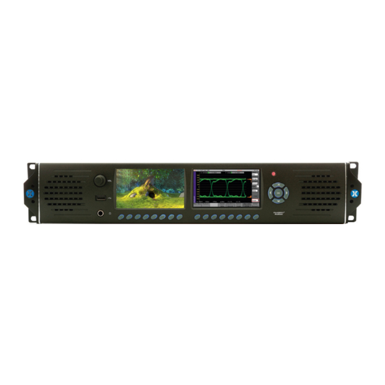
- Page 246 PHABRIX Rx 2000 A 2U height 19” (482cm) rack mount Rasterizer with 2 on-board displays and the ability to monitor up to 8 simultaneous inputs with loop through and is powerful enough to support simultaneous display of instruments across each module on HDMI Monitor Output.
- Page 247 S299-HD Ctrl The SMPTE 291M defined HD control data in HANC space. S305-SDTI The SMPTE 291M defined SDTI transport data packet in active frame space. S348-HDTI The SMPTE 291M defined HD-SDTI transport S315-Cam. Pos PHABRIX Rx 2000 Page A-6 User Manual...
- Page 248 Interface SMPTE 274M High Definition (HD) Image Formats for Television Production SMPTE-276M Television - Transmission of AES-EBU Digital Audio Signals Over Coaxial Cable SMPTE 292M Bit-Serial Digital Interface for High-Definition Television Systems PHABRIX Rx 2000 User Manual Page A-7...
- Page 249 A long-term time interval error, i.e., artifact below 10 Hz. Typically, all video equipment has the tendency to cause wander over a long period; these artifacts are not easily displayed in a meaningful way but are better logged as errors that exceed tolerances over a long period. PHABRIX Rx 2000 Page A-8 User Manual...
-
Page 250: Specifications
Rx 2000 – a unique audio video monitoring solution combining front panel instrumentation, via dual TFT screens, and integrated full range stereo speakers. Unique 2U tapered tilt-in-bay engineering with four Rx module bays. PHABRIX Rx 2000 User Manual Page B-1... - Page 251 Rx 1000 Rasterizer – a compact 1U, 19 inch rack-mount chassis with OLED display interface with four Rx module bays. Rx 500 Rasterizer – a compact 1U, half-rack width chassis with OLED display interface with two Rx module bays. PHABRIX Rx 2000 Page B-2 User Manual...
-
Page 252: Description
Front panel audio monitoring, provided by high quality speakers and/or a head phone socket, to allow the monitoring of the selected Audio channel. Four Module slots allowing the installation of Analyzer and Generator modules. PHABRIX Rx 2000 User Manual Page B-3... -
Page 253: Environmental Requirements
Power Requirements: AC 90 to 250 V at 50/60 Hz 70 W (max) Height: 2U, 88 mm (3.5 inch) Width: 443 mm (17.4 inch) Depth: 150 mm (5.9 inch) Weight: 1.9 kg (4.19 Ib) PHABRIX Rx 2000 Page B-4 User Manual... -
Page 254: Dimensions
Dimensions Front Panel Dimensions Back Panel Dimensions Top Panel Dimensions PHABRIX Rx 2000 User Manual Page B-5... -
Page 255: Side Panel Dimensions
Side Panel Dimensions PHABRIX Rx 2000 Page B-6 User Manual... -
Page 256: Front Panel
Output Power: 5 W RMS per channel (THD 0.5%) Frequency Response: 120 Hz to 20 kHz Headphone Output Connector: 1/4 Inch Stereo Jack Level: Adjustable Quantity: One (front mounted) Purpose: Local monitoring of audio PHABRIX Rx 2000 User Manual Page B-7... -
Page 257: Rx 2000 Rear Panel
Tri-level syncs (SMPTE 274M and SMPTE 296M) 600 mV pk-pk, PAL Black Burst (ITU624-4/SMPTE318) 1 V pk-pk, Composite NTSC (SMPTE 170M) 1 V pk-pk AES Input Label: AES IN Connector: Input Impedance: 75 ohm terminated PHABRIX Rx 2000 Page B-8 User Manual... -
Page 258: Sdi Out
Local Control USB Connector: USB 2 Type A Quantity: Three (1 x front mounted, 2 x rear mounted) Purpose: Keyboard and mouse control for HDMI® monitor output of instrument and software install- ation. PHABRIX Rx 2000 User Manual Page B-9... -
Page 259: Networking
10 - 18 Signal ground / 0 Volt GPIO - 0 (open drain with 10 kohm pull-up to +5 Volts) GPIO - 1 (open drain with 10 kohm pull-up to +5 Volts) PHABRIX Rx 2000 Page B-10 User Manual... - Page 260 Note also that the GPIO 4, 5, 6 and 7 output tally is set low when an error state occurs on an analyzer: Pin 4 = Analyzer 1 Pin 5 = Analyzer 2 PHABRIX Rx 2000 User Manual Page B-11...
- Page 261 GPIO Pin 5 GPIO Pin 6 GPIO Pin 7 Analyzer Slot High High High Analyzer Slot 1 High High High Analyzer Slot 2 High High High Analyzer Slot 3 High High High Analyzer Slot 4 PHABRIX Rx 2000 Page B-12 User Manual...
-
Page 262: Rx Modules
75 ohm terminated Analyzer Optical Inputs Label: OPTICAL A and B Purpose: To provide two optical video/audio inputs Type: SFP Optical Dual Receiver Module (option PHSFP-2R30-1310) Specifications: SMPTE 424M, SMPTE 292M, and SMPTE 259M PHABRIX Rx 2000 User Manual Page B-13... - Page 263 The Audio monitor (16 embedded audio channels, 48 kHz, 20-bit (SD-SDI) 24-bit (HD-SDI)) allows you to check the audio levels of the selected input. In addition to the visual display, the selected audio channel can be monitored via the front panel loudspeakers or headphone jack. PHABRIX Rx 2000 Page B-14 User Manual...
-
Page 264: Single Analyzer, Dual Input, Physical Layer Measurement
Analyzer Optical Inputs Label: OPTICAL A and B Type: SFP Optical Dual Receiver Module (Option PHSFP-2R30-1310) Specifications: SMPTE 424M, SMPTE 292M, and SMPTE 259M Purpose: To provide two optical video / audio inputs PHABRIX Rx 2000 User Manual Page B-15... - Page 265 The Audio monitor (16 embedded audio channels, 48 kHz, 20-bit (SD-SDI) 24-bit (HD-SDI)) allows you to check the audio levels of the selected input. In addition to the visual display, the selected audio channel can be monitored via the front panel loud speakers or head phone jack. PHABRIX Rx 2000 Page B-16 User Manual...
- Page 266 The Jitter monitor allows you to measure the amplitude of jitter present in the selected source against time. Controls are provided for scaling and filtering to isolate specific jitter types. PHABRIX Rx 2000 User Manual Page B-17...
-
Page 267: Single Analyzer, Single Generator
Loop through of SDI ANA IN Analyzer Optical Input Label: OPTICAL ANA Type: SFP Optical Single Receiver Module/Single Transmitter (Option PHSFP-RT30-1310) Specifications: SMPTE 424M, SMPTE 292M, and SMPTE 259M Purpose: To provide a single optical video/audio input PHABRIX Rx 2000 Page B-18 User Manual... - Page 268 The Picture viewer is provided to allow you to monitor the selected input to give confidence that the signal is present, is the correct subject (or feed), it is moving and looks OK. PHABRIX Rx 2000 User Manual Page B-19...
- Page 269 (DPX, YUV, TGA, BMP ) that can be used to check video levels, linearity, saturation, hue, color phase and frequency response. Pathogenic video test patterns such as Bars+Red, SMPTE Bars, Check Field that can be used to check that decoding, encoding and transmission processes are correct. PHABRIX Rx 2000 Page B-20 User Manual...
- Page 270 17 fixed Audio test tones (fixed 100 Hz to 20 kHz ), variable tones (1 Hz to 24 kHz in 1 Hz steps), intermittent tone, white noise or silence on audio pairs and audio groups. Audio level variable (0 to −100 dB in 1 dB steps). PHABRIX Rx 2000 User Manual Page B-21...
-
Page 271: Single Analyzer, Single Generator, Physical Layer Measurement
Loopthrough of SDI ANA IN Analyzer Optical Input Label: OPTICAL ANA Type: SFP Optical Single Receiver Module/Single Transmitter (option PHSFP-RT30-1310) Specifications: SMPTE 424M, SMPTE 292M, and SMPTE 259M Purpose: To provide a single optical video/audio input PHABRIX Rx 2000 Page B-22 User Manual... - Page 272 (DPX, YUV, TGA, BMP ) that can be used to check video levels, linearity, saturation, hue, color phase and frequency response. Pathogenic video test patterns such as Bars+Red, SMPTE Bars, Check Field that can be used to check that decoding, encoding and transmission processes are correct. PHABRIX Rx 2000 User Manual Page B-23...
- Page 273 (s) to be monitored (ideal for checking any embedded test pattern in the selected feed), the field to be checked and the graticule scale. PHABRIX Rx 2000 Page B-24 User Manual...
- Page 274 The Jitter monitor allows you to measure the amplitude of jitter present in the selected source against time. Controls are provided for scaling and filtering to isolate specific jitter types. PHABRIX Rx 2000 User Manual Page B-25...
-
Page 275: Dual Output Generator Module
32, 10-bit Line-based video test patterns such as color bars, ramp, color plate, multiburst and user defined (DPX, YUV, TGA, BMP ) that can be used to check video levels, linearity, saturation, hue, color phase and frequency response. PHABRIX Rx 2000 Page B-26 User Manual... - Page 276 17 fixed Audio test tones (fixed 100 Hz to 20 kHz ), variable tones (1 Hz to 24 kHz in 1 Hz steps), intermittent tone, white noise or silence on audio pairs and audio groups. Audio level variable (0 to −100 dB in 1 dB steps). PHABRIX Rx 2000 User Manual Page B-27...
-
Page 277: Aes Digital Audio Input / Output
Input Sample Rate: 32 kHz to 192 kHz Output Sample Rate: 48 kHz Input Bit Depth: 20 bit or 24 bit Output Bit Depth: 24 bit Purpose: AES digital audio pair Input and Output PHABRIX Rx 2000 Page B-28 User Manual... -
Page 278: Supported Video Formats
P or sF 24.00, P or sF 25.00, P or sF 29.97, P or sF 30.00, I 50.00, I 59.94, I 60.00 SMPTE 274M 1920 x 1080 4:4:4 (R’G’B’) / 12-bit P or sF 23.00, PHABRIX Rx 2000 User Manual Page B-29... -
Page 279: Level-A 2.97 Gb/S (Smpte 425M-A
P 30.00 *, P 50.00 *, P 59.94 *, P 60.00 * SMPTE 274M 1920 x 1080 4:4:4 (R’G’B’), P or sF 23.00 *, 4:4:4:4 (R’G’B’+A) / 10-bit P or sF 24.00 *, PHABRIX Rx 2000 Page B-30 User Manual... - Page 280 P or sF 30.00, I 50.00, I 59.94, I 60.00 SMPTE 274M 1920 x 1080 4:2:2 (Y’C’BC’R’) / 12 bit P or sF 23.00, P or sF 24.00, P or sF 25.00, P or sF 29.97, PHABRIX Rx 2000 User Manual Page B-31...
-
Page 281: Level-B 2.97 Gb/S (Smpte 425-B
Note: * Advanced Format Option required 3G Level-B 2.97 Gb/s (SMPTE 425-B) Payload Yype: 1 x SMPTE 372M dual-link payload 2 x SMPTE 292M HD 720 payloads 2 x SMPTE 292M HD 1080 payloads PHABRIX Rx 2000 Page B-32 User Manual... -
Page 282: Built-In Generator Formats (Cpu Module
3G-A SMPTE 274M 1920 x 1080 4:2:2 (Y’C’BC’R’) / 10 bit P 50.00, P 59.94, P 60.00 3G-B SMPTE 274M 1920 x 1080 4:2:2 (Y’C’BC’R’) / 10 bit P 50.00, P 59.94, P 60.00 PHABRIX Rx 2000 User Manual Page B-33... -
Page 283: Maintenance
Incorrect power adaptor used. Fire, natural disaster. Repair of instrument by non-PHABRIX approved agent Repair of damage caused by third party products. Repair of damage caused by improper use. Repair without proof of purchase. PHABRIX Rx 2000 User Manual Page C-1... -
Page 284: Product Registration
60° Celsius a warning dialog will be given. If the temperature rises above 65° Celsius the instrument will be switched off. Under both conditions, an event will be added to the event log to show what happened. PHABRIX Rx 2000 Page C-2 User Manual... -
Page 285: Software Maintenance
HDMI output monitor. The highest number is the latest release. Select the Install button and a confirmation dialog is displayed. Press Yes and the installation will start. You will see the following progress messages displayed: PHABRIX Rx 2000 User Manual Page C-3... - Page 286 Do not switch the instrument off until an installation has completed correctly. Once the installation has competed, if Reboot after Install is checked the instrument will re- start with the new software installed. If unchecked, switch the instrument off and on again manually. PHABRIX Rx 2000 Page C-4 User Manual...
-
Page 287: Rx File Structure
720p video standard is being used, only the test patterns in the 720yuv directory will be available. You may PHABRIX Rx 2000 User Manual... - Page 288 Fonts The fonts available for use by the generator to add text idents may be enhanced by downloading new True Type fonts (.ttf) into this directory. PHABRIX Rx 2000 Page C-6 User Manual...
- Page 289 The level above which alarms are logged in the Short Term Alarms column. Short Term Alarm Contains the integrated loudness values above the Short Term Threshold value. FCAP Frame Grab video clips with the extension .GRB are saved into this directory. PHABRIX Rx 2000 User Manual Page C-7...
-
Page 290: Applications
SDI audio, AES audio and HDMI audio. The following graphic shows a simplified audio block diagram of the Rx instrument (the numbering is referenced in the subsequent sections: PHABRIX Rx 2000 User Manual Page D-1... -
Page 291: Audio Channel Selection For Measurement And Analysis
The Generator - Output Audio window of the 4AES module is used to assign the connectors as inputs or outputs. The inputs (A In, B In, C In and D In) can be monitored using the instruments available with the module. PHABRIX Rx 2000 Page D-2 User Manual... -
Page 292: Decoded Dolby Audio (Dolby Decoder Module
Loudness window of the corresponding analyzer module configured in the Dolby Decoder menu. For example if Decoder 1 is configured to use SDI1 then Loudness window on analyzer 1 can monitor decoded audio. PHABRIX Rx 2000 User Manual Page D-3... - Page 293 The Lissajous display allows the phase relationship of a selected stereo audio pair from the decoded Dolby audio channels to be viewed on the corresponding Analyzer module. PHABRIX Rx 2000 Page D-4 User Manual...
-
Page 294: Audio Monitoring
(see number ③ ). The Source dropdown list allows the selection of the audio channels from an Analyzer module, the CPU AES In audio stereo pair or the Dolby Decoder module output (see number ④ ). PHABRIX Rx 2000 User Manual Page D-5... -
Page 295: Speaker / Headphone Audio Monitoring
The currently selected Rear Panel Audio pair in the Speaker/Headphone section of the Audio Monitoring window is routed via the HDMI output when the DVI Monitor checkbox is disabled (see number ⑦ ). PHABRIX Rx 2000 Page D-6 User Manual... -
Page 296: Hdmi Over Sdi Monitoring
This is done using the HDMI/CPU SDI Setup window. Note: The audio level of the SDI audio output is the same level as the currently selected audio pair in the Audio Monitoring window. PHABRIX Rx 2000 User Manual Page D-7... -
Page 297: Audio Routing
To ensure that the SDI audio is synchronous with the AES output, the System reference locking frame rate must be the same as the SDI output video being generated. This can be done from the “Ref” menu on the HDMI task bar. PHABRIX Rx 2000 Page D-8 User Manual... -
Page 298: Generator Sdi Audio Output
Master level or the individual channel levels. If the Dolby Decoder module is installed Decoded Dolby audio channels can also be embedded into the Generator SDI output signal. PHABRIX Rx 2000 User Manual Page D-9... - Page 299 www.phabrix.com PHABRIX products are continuously being updated. Please visit www.phabrix.com for latest product information...
Need help?
Do you have a question about the PHABRIX Rx 2000 and is the answer not in the manual?
Questions and answers