H3C S9820-64H Manual
Hide thumbs
Also See for S9820-64H:
- Installation manual (55 pages) ,
- Installation, quick start (4 pages) ,
- Manual (21 pages)
Table of Contents
Advertisement
Quick Links
Contents
1 Preparing for installation ·········································································· 1-1
Safety recommendations ································································································································ 1-1
Examining the installation site ························································································································· 1-1
Temperature/humidity ····························································································································· 1-2
Cleanliness ·············································································································································· 1-2
Corrosive gas limit ··································································································································· 1-2
EMI ·························································································································································· 1-3
Laser safety ············································································································································· 1-4
Installation tools ·············································································································································· 1-4
Installation accessories ··································································································································· 1-4
2 Installing the switch ·················································································· 2-6
Installing the switch in a 19-inch rack·············································································································· 2-6
Installation accessories ··························································································································· 2-6
Mounting bracket installation positions and switch dimensions ······························································ 2-7
Rack requirements ·································································································································· 2-8
Rack-mounting procedure at a glance ···································································································· 2-9
Attaching the mounting brackets, chassis rails, and grounding cable to the chassis···························· 2-10
Attaching cage nuts and slide rails to the rack ······················································································ 2-12
Mounting the switch in the rack ············································································································· 2-13
Grounding the switch ···································································································································· 2-15
Installing/removing fan trays ························································································································· 2-16
Installing a fan tray ································································································································ 2-17
Removing a fan tray ······························································································································ 2-17
Installing/removing power supplies ··············································································································· 2-18
Installing a power supply ······················································································································· 2-19
Removing a power supply ····················································································································· 2-20
Connecting power cords ······························································································································· 2-21
Connecting an AC power cord ·············································································································· 2-22
Connecting a DC power cord ················································································································ 2-22
Verifying the installation ································································································································ 2-23
3 Accessing the switch for the first time ···················································· 3-24
Connecting the switch to a configuration terminal························································································· 3-24
Connecting the console cable ······················································································································· 3-25
Connecting a DB9-to-RJ45 console cable ···························································································· 3-25
Connecting a USB-to-RJ45 console cable ···························································································· 3-26
Connecting a mini USB console cable ·········································································································· 3-28
Setting terminal parameters ·························································································································· 3-28
Powering on the switch ································································································································· 3-28
4 Setting up an IRF fabric ········································································· 4-29
IRF fabric setup flowchart ····························································································································· 4-29
Planning IRF fabric setup ······························································································································ 4-30
Planning IRF fabric size and the installation site ··················································································· 4-30
Identifying the master switch and planning IRF member IDs ································································ 4-30
Planning IRF topology and connections································································································ 4-31
Identifying physical IRF ports on the member switches ········································································ 4-32
Planning the cabling scheme ················································································································ 4-32
Configuring basic IRF settings ······················································································································ 4-34
Connecting the physical IRF ports ················································································································ 4-34
Accessing the IRF fabric to verify the configuration ······················································································ 4-34
5 Maintenance and troubleshooting ·························································· 5-36
Power supply failure ······································································································································ 5-36
Symptom ··············································································································································· 5-36
Solution ················································································································································· 5-36
i
Advertisement
Table of Contents

Related Manuals for H3C S9820-64H


Summary of Contents for H3C S9820-64H
-
Page 1: Table Of Contents
Contents 1 Preparing for installation ·········································································· 1-1 Safety recommendations ································································································································ 1-1 Examining the installation site ························································································································· 1-1 Temperature/humidity ····························································································································· 1-2 Cleanliness ·············································································································································· 1-2 Corrosive gas limit ··································································································································· 1-2 EMI ·························································································································································· 1-3 Laser safety ············································································································································· 1-4 Installation tools ·············································································································································· 1-4 Installation accessories ··································································································································· 1-4 2 Installing the switch ··················································································... - Page 2 Fan tray failure ·············································································································································· 5-36 Symptom ··············································································································································· 5-36 Solution ················································································································································· 5-36 Configuration terminal display issues············································································································ 5-36 No output ··············································································································································· 5-36 Garbled output ······································································································································ 5-37...
-
Page 3: Preparing For Installation
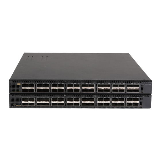
Preparing for installation The H3C S9820-64H switch is a high-density intelligent 100G switch developed for data center and high-end campus networks, providing powerful hardware forwarding capacity and abundant data center features. The switch provides the following ports and FRUs: •... -
Page 4: Temperature/Humidity
Temperature/humidity Maintain appropriate temperature and humidity in the equipment room in the acceptable range. For more information, see H3C S9820-64H Switch Hardware Information and Specifications. • Lasting high relative humidity can cause poor insulation, electricity leakage, mechanical property change of materials, and metal corrosion. -
Page 5: Emi
Average concentration (mg/m Maximum concentration (mg/m 0.05 CAUTION: As a best practice, control the corrosive gas concentrations in the equipment room at their average values. Make sure the corrosive gas concentrations do not exceed 30 minutes per day at their maximum values. -
Page 6: Laser Safety
Laser safety WARNING! Do not stare into any open apertures of operating transceiver modules or optical fiber connectors. The laser light emitted from these apertures might hurt your eyes. The switch is a Class 1M laser device. Installation tools No installation tools are provided with the switch. Prepare the following tools yourself: •... - Page 7 Part number in BOM Description Quantity Releasable cable tie User supplied Serial console cable 04042967 Optional USB-to-RJ45 console cable 0404A1EE Optional Mini USB console cable User supplied SFP port dust plug 14990101 1 (provided) QSFP port dust plug Same number as the QSFP28 1499A01G ports...
-
Page 8: Installing The Switch
Installing the switch CAUTION: Keep the tamper-proof seal on a mounting screw on the chassis cover intact, and if you want to open the chassis, contact H3C for permission. Otherwise, H3C shall not be liable for any consequence caused thereby. CAUTION: When installing the switch, always wear an ESD wrist strap and make sure the wrist strap makes good skin contact and is reliably grounded. -
Page 9: Mounting Bracket Installation Positions And Switch Dimensions
• A pair of mounting brackets (2150A0EH), as shown in Figure2-2. • A pair of cable management brackets (each attached to a mounting bracket), as shown in Figure2-2. • A rack-mount rail kit, including a pair of slide rails (2150A05N) and a pair of chassis rails, as shown in Figure2-3. -
Page 10: Rack Requirements
Figure2-4 Installing the mounting brackets at the port side 26mm (1.02 in) 88.1mm (3.47 in) 525mm (20.67 in) 77mm (3.03 in) 15mm (0.59 in) (1) Power supply handle (2) Mounting bracket (3) Cable management bracket Figure2-5 Installing the mounting brackets at the power supply side 26mm (1.02 in) 88.1mm (3.47 in) 538mm... -
Page 11: Rack-Mounting Procedure At A Glance
Mounting Distance bracket between the Chassis dimensions Rack requirements installation front and rear position rack posts • Width—440 mm (17.32 in) • Height—88.1 mm (3.47 in)/2 Mounting • Depth—630 mm (24.80 in) brackets installed 506 to 778 mm near the power (19.92 to 30.63 in) 540 mm (21.26 in) for the ... -
Page 12: Attaching The Mounting Brackets, Chassis Rails, And Grounding Cable To The Chassis
Attaching the mounting brackets, chassis rails, and grounding cable to the chassis As shown in Figure2-7, the switch provides two installation positions on the two sides for mounting brackets: one near the power supply side and one near the port side. A primary grounding point (with a grounding sign) and an auxiliary grounding point are available on the switch. - Page 13 If the grounding cable length or grounding lug type cannot meet your requirement, make an applicable grounding cable or contact H3C Support. The grounding screws provided with the switch are applicable to both the primary and auxiliary grounding points.
-
Page 14: Attaching Cage Nuts And Slide Rails To The Rack
Unpack the grounding cable and grounding screws. Use the grounding screws to attach the single-hole grounding lug or two-hole grounding lug of the grounding cable to the grounding point and then fasten the screws, as shown in Figure2-10 and Figure2-11. As a best practice, use a torque of 30 kgf-cm (2.94 Nm) to fasten the grounding screws. -
Page 15: Mounting The Switch In The Rack
Figure2-12 Marking cage nut installation holes for attaching mounting brackets Install cage nuts (user-supplied) in the marked mounting holes in the rack posts. Align the screw holes in one slide rail with the cage nuts in a rear rack post. Use the user-supplied M6 screws to attach the slide rail to the post, as shown in Figure2-13. - Page 16 a. Supporting the bottom of the switch, aligns the chassis rails with the slide rails on the rack posts. b. Pushes the switch slowly into the rack so that the slide rails slide into and reach out the chassis rails and the mounting brackets are flush against the rack posts. Another person uses screws (user-supplied) to attach the mounting brackets to the rack.
-
Page 17: Grounding The Switch
Grounding the switch CAUTION: • Correctly connecting the grounding cable is crucial to lightning protection and EMI protection. • To guarantee the grounding effect, connect the switch to a grounding strip in the equipment room by using the grounding cable provided with the switch. The power input end of the switch has a noise filter, whose central ground is directly connected to the chassis to form the chassis ground (commonly known as PGND). -
Page 18: Installing/Removing Fan Trays
Select fan trays for the switch based on the airflow requirements. For the fan tray specifications, see H3C S9820-64H Switch Hardware Information and Specifications. The installation and removal procedures are the same for the fan trays. The following installation and removal procedures use the LSWM1BFANSC fan tray as an example. -
Page 19: Installing A Fan Tray
For more information about the command, see device management in fan prefer-direction H3C S9820-64H Switch Fundamentals Command Reference. The switch supports shipping with fan trays and power supplies installed. If your switch came with fan trays preinstalled, skip this section. -
Page 20: Installing/Removing Power Supplies
PWR1 and PWR3 installed with filler panels. The switch supports 2+1 and 2+2 power supply redundancy. You can install two to four power supplies for the switch. For information about the power supplies available for the switch, see H3C S9820-64H Switch Hardware Information and Specifications. -
Page 21: Installing A Power Supply
Installing a power supply CAUTION: • Follow the forward inertia of the power supply when inserting it into the chassis, and make sure the power supply has firm contact with the connectors on the backplane. • To prevent damage to the connectors inside the switch chassis, insert the power supply gently. If you encounter a hard resistance while inserting the power supply, pull out the power supply and insert it again. -
Page 22: Removing A Power Supply
Figure2-22 Installing a power supply (LSVM1AC650) Removing a power supply CAUTION: The switch supports 2+1 or 2+2 power supply redundancy. When the switch is configured with four power supplies, removing one or two power supplies does not affect the operation of the switch. When the switch has only two power supplies installed, removing power supplies powers off the switch or causes power insufficiency. -
Page 23: Connecting Power Cords
Figure2-23 Removing a DC power cord (1) Press the tabs on the power cord connector with your thumb and forefinger (2) Pull the power cord connector out Figure2-24 Removing the power supply (1) Pivot the latch to the right with your thumb (2) Pull the power supply out Connecting power cords WARNING! -
Page 24: Connecting An Ac Power Cord
Connecting an AC power cord Insert the female connector of the AC power cord supplied with the power supply into the power receptacle on the power supply. Use a cable tie to secure the power cord to the handle of the power supply, as shown in Figure2-25. -
Page 25: Verifying The Installation
Figure2-26 Connecting the DC power cord for an LSVM1DC650 power supply If the provided DC power cord cannot meet your connection requirements, use the following table to prepare a suitable copper cable as the DC power cord. Table2-4 Requirements for a suitable DC power cord Minimum cross Cross sectional Maximum cross... -
Page 26: Accessing The Switch For The First Time
The signal pinout for the RJ-45 connector of a serial console cable varies by vendor. To avoid abnormal configuration terminal display, use a serial console cable provided by H3C. For more information, see Table3-2. To prepare a serial console cable yourself, make sure the signal pinout for the RJ-45 connector is the same as that shown in Table3-3. -
Page 27: Connecting The Console Cable
Table3-2 Console cable views Product code for the Console cable type Console cable view recommended H3C console cable DB9-to-RJ45 console cable 04042967 USB-to-RJ45 console cable 0404A1EE Mini USB console cable User supplied, Connecting the console cable Connecting a DB9-to-RJ45 console cable CAUTION: •... -
Page 28: Connecting A Usb-To-Rj45 Console Cable
Click the following link, or copy it to the address bar on your browser and download the USB-to-RJ45 console driver. http://www.h3c.com/en/home/USB_to_RJ45_Console/ View the TXT file Read me in the Windows folder to check whether the Windows system of the configuration terminal supports the driver. - Page 29 Figure3-3 Driver installation wizard Click Finish after the drive installation is completed. Figure3-4 Finishing the driver installation Connect the standard USB connector of the cable to the USB port of the configuration terminal. 3-27...
-
Page 30: Connecting A Mini Usb Console Cable
After the startup completes, you can access the CLI to configure the switch. For more information about the configuration commands and CLI, see H3C S9820-64H Switch Configuration Guides and H3C S9820-64H Switch Command References. -
Page 31: Setting Up An Irf Fabric
Setting up an IRF fabric You can use H3C IRF technology to connect and virtualize multiple S9820-64H switches into a large virtual switch called an "IRF fabric" for flattened network topology, and high availability, scalability, and manageability. IRF fabric setup flowchart... -
Page 32: Planning Irf Fabric Setup
For more information about master election, see H3C S9820-64H Switch Virtual Technologies Configuration Guide. Prepare an IRF member ID assignment scheme. An IRF fabric uses member IDs to uniquely identify and manage its members, and you must assign each IRF member switch a unique member ID. -
Page 33: Planning Irf Topology And Connections
Planning IRF topology and connections You can create an IRF fabric in daisy chain topology, or more reliably, ring topology. In ring topology, the failure of one IRF link does not cause the IRF fabric to split as in daisy chain topology. Rather, the IRF fabric changes to a daisy chain topology without interrupting network services. -
Page 34: Identifying Physical Irf Ports On The Member Switches
QSFP+ transceiver module and fiber or a QSFP+ cable do not support IRF connections. Planning the cabling scheme You can use QSFP28 cables or QSFP28 transceiver modules and fibers to connect the S9820-64H switches for IRF connections. If the switches are all in one equipment room, choose QSFP28 cables for IRF connections. If the switches are far away from one another, choose QSFP28 transceiver modules and fibers for IRF connections. - Page 35 For more information about available cables, see H3C S9820-64H Switch Hardware Information and Specifications. The following subsections describe several IRF connection schemes by using the QSFP28 cables and QSFP28 transceiver modules and fibers. As a best practice, use the ring topology for IRF connections.
-
Page 36: Configuring Basic Irf Settings
Create a Layer 3 interface, assign it an IP address, and make sure the IRF fabric and the remote network management station can reach each other. Use Telnet or SNMP to access the IRF fabric from the network management station. (See H3C S9820-64H Switch Fundamentals Configuration Guide.) Verify that you can manage all member switches as if they were one node. - Page 37 To avoid IP address collision and network problems, configure at least one multi-active detection (MAD) mechanism to detect the presence of multiple identical IRF fabrics and handle collisions. For more information about MAD detection, see H3C S9820-64H Switch Virtual Technologies Configuration Guide.
-
Page 38: Maintenance And Troubleshooting
Power supply failure Symptom The status LED on a power supply is not steady green (active state) or flashing green (standby state) For more information about the power supply LED, see H3C LSVM1AC650 & LSVM1DC650 Power Modules User Manual. Solution To resolve the issue: Verify that the power cord is connected correctly. - Page 39 Verify that the power system is operating correctly. Verify that the console cable is connected correctly. Verify that the console cable does not have any problems and the terminal settings are correct. If the issue persists, contact H3C Support. Garbled output Symptom The output of the configuration terminal is garbled.
Need help?
Do you have a question about the S9820-64H and is the answer not in the manual?
Questions and answers