Table of Contents
Advertisement
Quick Links
MODEL TMG-TPD12
TMG-TPD12
PRODUCT MANUAL
v2022.10.27
48" 3-POINT HITCH POST
HOLE DIGGER
Please read and understand the product manual completely before assembly
Check against the parts list to make sure all parts are received
Wear proper safety goggles or other protective gears while in assembly
Do not return the product to dealer. They are not equipped to handle your requests.
Missing parts or questions on assembly?
Please call: 1-877-761-2819 or email: cs@tmgindustrial.com
www.tmgindustrial.com
Toll Free:1-877-761-2819
Advertisement
Table of Contents

Related Manuals for TMG TMG-TPD12

Summary of Contents for TMG TMG-TPD12
- Page 1 MODEL TMG-TPD12 TMG-TPD12 PRODUCT MANUAL v2022.10.27 48” 3-POINT HITCH POST HOLE DIGGER Please read and understand the product manual completely before assembly Check against the parts list to make sure all parts are received Wear proper safety goggles or other protective gears while in assembly Do not return the product to dealer.
-
Page 2: Table Of Contents
TABLE OF CONTENTS SAFETY INSTRUCTIONS......................3 PARTS DESCRIPTION AND FUNCTION..................5 PRODUCTS SPECIFICATIONS....................6 PRODUCTS SAFETY DECALS....................6 UNPACKING & ASSEMBLY......................7 CONNECTING TRACTOR......................15 OPERATING ESSENTIALS......................19 MAINTENANCE SCHEDULE....................21 TROUBLESHOOTING......................21 EXPLODED VIEW & PARTS LIST....................22 www.tmgindustrial.com 2/24 Toll Free:1-877-761-2819... -
Page 3: Safety Instructions
SAFETY INSTRUCTIONS Safety First You are responsible for the safe operation and maintenance of your post hole digger. You must ensure that you and anyone else who is going to operate, maintain or work around the post hole digger is familiar with the operating and maintenance procedures and related SAFETY information contained in this manual. - Page 4 19. Ensure the tractor engine is switched off and the parking brake is applied before performing any inspection or maintenance on the digger. If it is necessary to raise the machine for such work ensure it is properly supported. Do not rely on the tractor hydraulics for support.
-
Page 5: Parts Description And Function
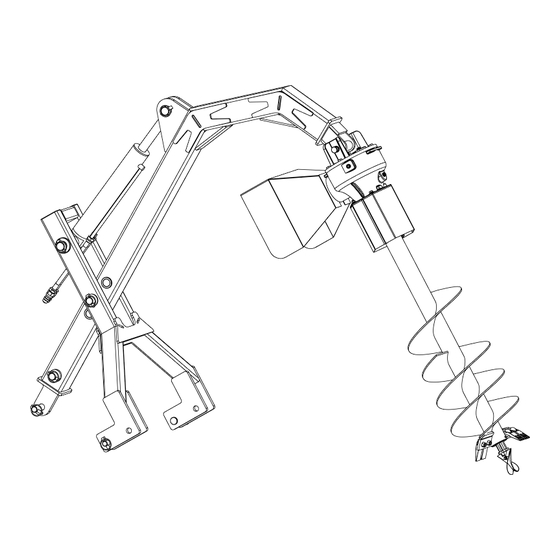
PARTS DESCRIPTION AND FUNCTION 2. Frame Weldment 1. Hydraulic Cylinder Assembly 3. Gear Box 5. Drill assembly 4. Hitch bracket 1. Hydraulic Cylinder 4. Hitch Bracket Adjust the position. Connect tractor. 2. Frame Weldment 5. Drill Assembly Support the product. Drill hole. -
Page 6: Products Specifications
PRODUCTS SPECIFICATIONS Model No TMG-TPD12 Auger diameter 12” Max. auger depth 48” Output bore 2” Tractors horsepower 35-65hp 3-point linkage CAT 1 & CAT 2 Length 1770mm Width 790mm Weight 215mm Boom Size 100×100mm Gearbox 60HP PTO Safety Yes-Protective Cover PRODUCTS SAFETY DECALS www.tmgindustrial.com... -
Page 7: Unpacking & Assembly
UNPACKING & ASSEMBLY 1. After unpacking, check the following components www.tmgindustrial.com 7/24 Toll Free:1-877-761-2819... - Page 8 DESCRIPTION DESCRIPTION Frame weldment Connecting pin 35x100 Hitch bracket Gearbox connecting shaft 22x185 Upper suspension plate R Pin 4 Gearbox Pin 12 Hydraulic cylinder assembly Full-thread hexagon bolts M8×20 Gearbox protective hood Spring washer Ø8 Drilling bit safety cover Large plain washer Connecting pin 24.5x96 Hexagon head bolts M12×90 Plain washer Ø12...
- Page 9 2. Install suspension components Installation steps: Place the UPPER SUSPENSION PLATE (25) and the FRAME WELDMENT (10) as shown in the figure above, align the mounting holes, connect them in series with the ADJUSTING PLATE SHAFT (5), and install the lock pin (14) to fix it. The other CONNECTING SHAFTS (4) and locking pins (14) are installed in cooperation with the ADJUSTING PLATE SHAFT (5).
- Page 10 3. Install the cylinder assembly Installation steps: 1. Place the HYDRAULIC CYLINDER ASSEMBLY (21) in the position as shown in the figure above, pass through the pins on both sides, pass through the upper lifting frame welding part and the suspension welding part respectively, connect them in series with the cylinder, and pass through the CONNECTING SHAFT (11) and CONNECTING PIN (12) fixed.
- Page 11 4. Install the gearbox Installation steps: Place the GEAR BOX (23) in the position shown in the figure above, align the mounting holes on the lifting frame, insert the GEARBOX CONNECTING SHAFT (9), and fix it with R PIN (22). PART NO.
- Page 12 5. Install the gearbox guard 16/18/20 Installation steps: Place the GEARBOX PROTECTIVE COVER (7) in the position shown in the figure above, install the PLAIN WASHER (20), SPRING WASHER (20), and BOLT (16) in sequence, and fasten it. Importance: All bolts are locked in place without shaking. NOTE: M8 Torque is 22~30 N·m WARNING: Once the assembly bolts are not fastened in place, there will be abnormal noises when the machine is working.
- Page 13 6. Install the drill guard 16/18/20 A1/A9/A10 Installation steps: 1. Place the PRE-ASSEMBLED DRILLING BIT SAFETY COVER (1,2) in the position shown in the figure above, and fasten it on the gear box with SPRING WASHER (18), PLAIN WASHER (20) and BOLTS (16). 2.
- Page 14 7. Installing the drill bit assembly Release A1/A9/A10 A1/A9/A10 Installation steps: 1. First loosen the bolts on the drill bit guard, remove the drill bit guard. 2. Install the DRILL BIT ASSEMBLY on the gearbox, align the mounting holes on the gearbox, install the BOLTS (A10), PLAIN WASHERS (A9) and tighten the NUT (A1).
-
Page 15: Connecting Tractor
In the process of connection, when the tractor is the moving, if there is people between the tractor and working machine, it may cause injury accident. Be sure no people stand between the tractor and working machine during the tractor moving. LOWER LIFTING PIN TYPES TMG-TPD12 CAT1 &CAT2 2. Connection and adjustment... - Page 16 If the magnitude of the tractor towing arms is too narrow, adjust the left suspension pin inward as below: Adjust Elastic cylindrical Left suspension pin d. Adjust angle, to obtain the most appropriate cutting angle, adjust the upon 3-point linkage suspension to ensure the suitable cutting angle.
- Page 17 3. PTO installation DANGER ! If you use no plastic cover to protect the coupling, it is possible to be involved in the occurrence of injuries. Do not use no ● plastic casing coupling. If you use damaged couplings, injuries may occur entangled. Couplings if damaged, replace it immediately. Please check if ●...
- Page 18 3. After connection, fixed the chain to prevent the plastic cover rotation 4. Max rotation angle of coupling NOTED ! If the shaft beyond its maximum operating angle of rotation at work, there will be unexpected injury accident. Be sure to fix the tractor three-point suspension before use.
-
Page 19: Operating Essentials
OPERATING ESSENTIALS ASSEMBLY Attaching to the Tractor Standard Model 1. Attach the main support boom to the top link of the tractor with a cat 1 top link pin. 2. Connect the ‘A’ frame to the lower link arms of the tractor with cat 1 lower link pins. 3. - Page 20 Changing the Auger All augers are the same length and are attached in the same way by two shear bolts through the gearbox output shaft. To remove the auger, raise the boom to allow the auger to hang vertically then lower until the end of the auger is about 100mm above the ground.
-
Page 21: Maintenance Schedule
3. Lower the auger slowly using the hydraulics until it starts to dig. Continue to lower the auger slowly ensuring it does not corkscrew into the ground. It may be necessary to clear the auger by raising it from time to time, only using the remote control lever. -
Page 22: Exploded View & Parts List
EXPLODED VIEW & PARTS LIST 1. Explosion diagram of main components 16 18 20 www.tmgindustrial.com 22/24 Toll Free:1-877-761-2819... - Page 23 PARTS LIST PART NO. DESCRIPTION PART NO. DESCRIPTION Drill bit safety cover Pin 12 Drill bit guard Full-thread hexagon bolts M6×20 Hitch pin-lower 22x114 Full-thread hexagon bolts M8×20 Connecting pin 24.5x96 Lock nut M6 Adjusting plate shaft 30x150 Spring washer Ø8 Hitch connecting pin 30x260 Plain washer Ø6 Gearbox protective hood...
- Page 24 www.tmgindustrial.com 24/24 Toll Free:1-877-761-2819...
Need help?
Do you have a question about the TMG-TPD12 and is the answer not in the manual?
Questions and answers