Advertisement
Quick Links
Replacement of installed sounders
Sounders, part no 45681-266 may be used as a direct replacement of existing sounders 45681-262.
Protocol bit use
Output Bit Settings
2
1
0
0
0
0
0
1
0
1
NB Output bit 2 is not used
Input bits 2, 1, 0 confi rm the receipt of the corresponding output bits
Troubleshooting
Before investigating individual units for faults, it is important to check the system wiring is fault
free. Earth faults on data loops may cause communication errors. If an XP95 test set is used to
test the sounder operation may be intermittent. To avoid this, operate the sounder and exit the
single address test.
Fault Finding
Problem
Possible Cause
No response or missing
Incorrect address setting
Incorrect loop wiring
Too many sounders between isolators
Sounder fails to operate
Control panel has incorrect cause and effect programming
© Apollo Fire Detectors Limited 2003-9
Apollo Fire Detectors Ltd, 36 Brookside Road, Havant, Hants, PO9 1JR, England
Tel +44 (0)23 9249 2412 Fax +44 (0)23 9249 2754
Email: techsales@apollo-fi re.co.uk
Sounder action
0
0
Sounder off
1
Alarm alternates
0.5sec 510Hz,
0.5sec 610Hz
0
Alarm intermittent
1 sec off, 1 sec 510Hz
1
Alarm alternates
0.5sec 510Hz, 0.5 sec 610Hz
www.apollo-fi re.co.uk
PP2143/2005/Issue 6
General
This guide describes the installation of the following sounder
Part number
45681-266
The sounder may be connected only to control panels which use either the XP95 or the Discov-
ery protocol.
Note: The Intelligent Base Sounder is Type A, ie, it is not suitable for outdoor use.
The Intelligent Base Sounder complies with the requirements of EN54–3 : 2001.
Mounting Instructions
The Base Sounder may be secured to a UK standard conduit box or surface mounted (provid-
ing there is access through the surface for cabling). Set the address and select the desired
output before securing the XP95 isolating base to the sounder.
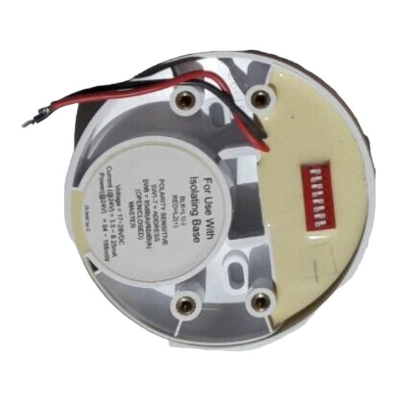
Wiring details, Part no. 45681-266
Note: The sounder is polarity sensitive (supply reversal protected) and will not function if wired
incorrectly.
Connect the loop cables to the isolating base terminal block, observing polarity. Connect
the red and black wires from the sounder to the XP95 base L1 and L2 terminals, not the base
terminal block. Note that the red and black wire connections are the reverse of those to other
bases (Fig 1). The wiring terminals accept solid or stranded cables up to 2.5mm².
Intelligent Base Sounder
for use with isolating bases
Installation Guide
Comments
for use with XP95 isolating bases secured by two M4 x 20 screws
supplied (isolating base not supplied with sounder)
Advertisement

Related Manuals for Apollo 45681-266


Summary of Contents for Apollo 45681-266
- Page 1 PP2143/2005/Issue 6 Replacement of installed sounders Sounders, part no 45681-266 may be used as a direct replacement of existing sounders 45681-262. Protocol bit use Output Bit Settings Sounder action Sounder off Alarm alternates 0.5sec 510Hz, 0.5sec 610Hz Alarm intermittent 1 sec off, 1 sec 510Hz...
- Page 2 (part no. 55000-720) or isolating bases (part no. 45681-321/284) is 20, depending on the loop 1010000 1111000 1001100 1100010 1011010 loading. Apollo's Loop Calculator is a program available as a free download from www.apollo- 0110000 0000100 0101100 0010010 0111010 fi re.co.uk and can be used to check the loading of any proposed loop design.
Need help?
Do you have a question about the 45681-266 and is the answer not in the manual?
Questions and answers