
Subscribe to Our Youtube Channel
Related Manuals for Gewiss CHORUS GW 16976CB


Summary of Contents for Gewiss CHORUS GW 16976CB
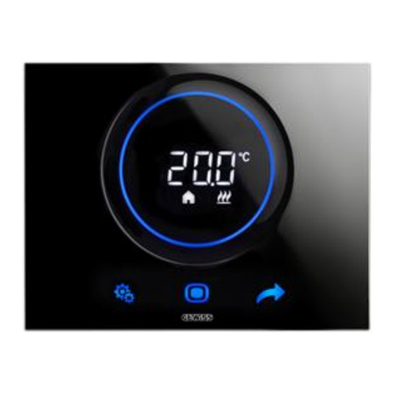
- Page 1 KNX Thermo ICE Thermostat (surface-mounting) Photo: GW16976CN - Black GW 16976CB - GW 16976CN - GW 16976CT Technical Manual...
-
Page 2: Table Of Contents
Contents Introduction ..............................5 Application ..............................5 2.1 Association limits ............................7 “Information” menu ............................. 8 “Main” menu ............................... 8 4.1 Parameters of the ............................9 4.1.1 Delay time from power on and first transmission ..................9 4.1.2 Thermostat functioning ..........................10 4.1.3 Functioning type setting .......................... - Page 3 9.1.9 Feedback sending trigger object ......................... 75 10 “Scenes” menu ............................76 10.1 Parameters of the ............................76 10.1.1 Scenes function ............................76 Scene number n (1 ≤ n ≤ 8) ........................77 10.1.2 10.1.3 Parameters to memorize while storing......................77 11 “Humidity”...
- Page 4 19 ETS programming error feedback ......................115 20 Device malfunctioning error feedback ....................117 21 Device malfunctioning warning feedback ....................118 21.1 Feedback from external devices ....................... 118 21.2 Feedback of ETS download in progress ....................120 22 Communication objects .......................... 121...
-
Page 5: Introduction
1 Introduction This manual describes the functions of the “KNX Thermo ICE Thermostat (surface-mounting)” (GW16976CB - GW16976CN - GW16976CT) device and how they are set and configured with the aid of the ETS configuration software. 2 Application The KNX THERMO ICE (surface-mounting) manages the temperature of the room where it's installed, and can also manage a humidification/dehumidification system alongside the temperature control system, or intervene on the temperature control system to regulate the Humidity in the air. - Page 6 • via the BUS, with distinct 1-bit objects (OFF, ECONOMY, PRECOMFORT, COMFORT); • via the BUS, with 1-byte objects. Operating setpoint definition • via the BUS, with 2-byte objects. Temperature measurement • with the built-in sensor; • with a combination of built-in sensor/external sensor KNX/external sensor NTC , with the definition of the relative weights.
-
Page 7: Association Limits
2.1 Association limits Maximum number of group addresses: Maximum number of associations: This means that up to 254 group addresses can be defined, and up to 254 associations can be made (between communication objects and group addresses). -
Page 8: "Information" Menu
“Information” menu Like every KNX device, this one requires first of all the programming of the physical or individual address during the initial start-up. This is not done by pressing a push-button and dedicated programming LED, as is the case with most devices, but directly from the menu of the touchscreen display of the ICE thermostat. -
Page 9: Parameters Of The
Figure 4.1 shows the structure of the menu: Fig. 4.1 – “Main” menu 4.1 Parameters of the 4.1.1 Delay time from power on and first transmission To ensure that, with several devices in the line, the telegrams sent by the various devices do not collide when the BUS voltage is reset, you can define a time limit after which the device can transmit the telegrams on the BUS following a BUS voltage failure/reset. -
Page 10: Thermostat Functioning
If the values 11..21 seconds (depending on physical address) 5..9 seconds (depending on physical address) are set, the device automatically calculates the transmission delay on the basis of an algorithm that examines the physical address of the device itself; the values indicated (11/21 or 5/9) indicate the minimum and maximum limits of the value range that can be calculated. -
Page 11: Functioning Type Setting
4.1.3 Functioning type setting The device functioning type temperature control (heating/cooling) can be managed either manually or autonomously (by the device itself). The manual method can be managed via the local navigation menu or BUS commands that allow switching between types, changing the dedicated parameter. The automatic method is based on the principle of an interdiction area, or “dead zone”, i.e. -
Page 12: Parameters Local Modification And Base Parameters Values Overwrite During Download
4.1.4 Parameters local modification and Base parameters values overwrite during download The “Parameters local modification” parameter is used to enable or otherwise the modification of the thermostat operating parameters via the relative local menu. The values that can be set are: ... -
Page 13: Hour Modification Via Bus
The exact cleaning function activation and deactivation moments are signalled to the user via a special sound effect (used only with this function) and a special light effect (also used only with this function) on the backlighting of the touch push-buttons and the slider. There are two ways of activating the Plate cleaning function: 1. - Page 14 If enable is selected, the l’Communication objects Time input (Data Point Type: 10.001 DPT_TimeOfDay) is visualised, allowing the device to receive the values for the day of the week and the time from the BUS. The information about the day of the week is not used by the device. When the BUS or auxiliary voltage is restored, the status read command (read request) should be sent via the Object Time input in order to update the time shown.
-
Page 15: Master/Slave Control Type Orstand Alone
The “Set daylight saving time from bus” parameter is used to enable and visualise the communication objects Daylight saving time input (Data Point Type: 1.001 DPT_Switch), which the device uses to obtain information about the status of the time system being used. The values that can be set are: ... -
Page 16: Remote Parameters Setting
HVAC mode (default value) setpoint 4.1.8 Remote parameters setting Even if the device functions as stand alone, it can still receive various commands from remote units via the BUS. The “Remote parameters setting” parameter visualises the various configuration items for remote thermostat control. - Page 17 Function/Object Size Priority Reactivation after manual switch-off (if reactivation is manual and via remote commands) Local operating mode change (Mode button key) Scene 1 byte HVAC mode input (Setpoint input) 1 byte (2 byte) HVAC mode input comfort 1 bit HVAC mode input precomfort 1 bit HVAC mode input economy...
- Page 18 Vice versa, if deactivate object with lower priority is selected and a 1-bit HVAC mode activation command with a higher priority than the currently active one is received, the mode of the new object will be set and the activation status of objects with a lower priority will be set at 0 (deactivated). The values that can be set for the “Reception 1 bit mode with priority <...
- Page 19 from 1 to 20 in steps of 1 (default value 5) Regardless of whether the mode setpoints are modified via the local menu or with a remote BUS command, if the stand alone control type or master/slave is HVAC mode, there is a value setting limit between the setpoints belonging to the same operating type.
- Page 20 disable (default value) enable increase/decrease step regulation Selecting enable increase/decrease step regulation visualises the communication objects Setpoint temporary forcing regulation (Data Point Type: 1.007 DPT_Step). If the value “1” is received on this object, the current setpoint will be temporarily increased by the value defined in the “Setpoint temporary forcing regulation step [0.1 °C]”...
-
Page 21: Heating/Cooling Control Logics And Algorithms
local control only (default value) local and remote control Setting Local control only, all the remote commands received from the master device and that involve changing the HVAC mode or modifying the operating setpoint are suspended and only implemented when local switch- off has been deactivated. - Page 22 If is selected the continuous proportional integral and parameters are visualised “Select heating system”, “Proportional band [P23]”, “Integration time [P24]” in “Min % variation for continuous sending [P11]” the menu Heating along withcommunication objects % command valve heating (Data Point Type: 5.001 DPT_Scaling) the via which the device sends the command telegrams..
- Page 23 “Integration time [P24]” and “Min % variation for continuous sending [P11]” parameters are visualised (depending on the set valve management type - two points ON-OFF / 0%-100% or continuous proportional integral respectively), along with ”Operation limit fan coil [tenths of °C] [P26]”, “Proportional band [P23]”, “Integration time [P24]”...
- Page 24 two points 0%-100% continuous proportional integral Selecting two points ON-OFF visualises the communication objects Heating/cooling valve switch (Data Point Type: 1.001 DPT_Switch), via which the device sends the command telegrams to the solenoid valve. Selecting two points 0%-100% visualises the communication objects % command valve heating/cooling (Data Point Type: 5.001 DPT_Scaling), via which the device sends the command telegrams to the solenoid valve.
- Page 25 If the control algorithm selected for Heating, Cooling or Heating/Cooling is fan coil with ON-OFF speed control (ON-OFF), the V1 fan switching heating, V1 fan switching cooling, V2 fan switching heating,V2 fan switching cooling, V3 fan switching heating and V3 fan switching cooling (Data Point Type: 1.001 DPT_Switch) communication objects are also made available to control the first, second and third fan coil speed respectively.
- Page 26 “1” switches the mode to AUTO. To activate the fan at the required speed when the fan coil is in MANUAL, the defined fan speed intervention threshold must be exceeded. The switch from MANUAL to AUTO in both speed regulation modes is made by immediately reassessing the speed value according to the algorithm.
- Page 27 Fan coil speed selection: AUTOMATIC (0-100%) Speed V = (int(V / 10)*10) + 10) V = (V + 10) >= 2nd Speed V = X * 10 (with X from 0 to 10) Fan coil speed selection: MANUAL (0-100%) When the BUS or auxiliary voltage is reset, the fan coil mode is the one that was active prior to the power failure.
-
Page 28: Control Algorithms
4.2 Control algorithms Regardless of whether the control logic is shared by the two functioning types or is separate, depending on the algorithm selected the logic is as follows: 4.2.1 Two points ON-OFF The algorithm used for managing the temperature control system is the classic type, called "2-point control". This type of control involves the switch-on and switch-off of the temperature control system following a hysteresis cycle. -
Page 29: Two Points 0% - 100
4.2.2 Two points 0% - 100% The algorithm used for managing the temperature control system is the classic type, called "2-point control". This type of control involves the switch-on and switch-off of the temperature control system following a hysteresis cycle. This means there isn't a single threshold that discriminates between system ON and system OFF, but two. - Page 30 basis of the difference between the defined setpoint and the measured temperature. Two components are needed to calculate the output function: the proportional component and the integral component. Proportional component In the proportional component, the output function is proportional to the error (difference between setpoint and measured temperature).
- Page 31 Temperature setpoint Proportional band narrowing Time Integral component The contribution of the integral period is proportional to the error (difference between setpoint and measured temperature) and its duration. The integral is the sum of the instantaneous error for every moment of time, and it provides the accumulated offset that should have been corrected previously.
- Page 32 temperature has been reached, it continues to provide small heat contributions to compensate for the environmental heat dispersion. 100% Output function Cooling valve t [min] As the diagram shows, the device keeps the cooling system switched on for a Cycle time [P10] percentage that depends on the output function of the proportional integral control;...
-
Page 33: Continuous Proportional Integral
4.2.4 Continuous proportional integral The algorithm used to manage the temperature control system allows you to drastically reduce the times subject to thermal inertia and introduced by the 2-point control, called continuous control. This type of control involves the continuous control of the difference between the measured temperature and the fixed setpoint, and therefore the sending of the commands for the modulation of the temperature control system power. - Page 34 Temperature setpoint Proportional band narrowing Time Integral component The contribution of the integral period is proportional to the error (difference between setpoint and measured temperature) and its duration. The integral is the sum of the instantaneous error for every moment of time, and it provides the accumulated offset that should have been corrected previously.
-
Page 35: Fan Coil With On-Off Speed Control (On-Off)
With this type of algorithm, there is no longer a hysteresis cycle on the heating device, so the inertia times (system heating and cooling times) introduced by the 2-point control are eliminated. This produces energy savings because the system does not remain switched on when it's not needed and, once the required temperature has been reached, it continues to provide small heat contributions to compensate for the environmental heat dispersion. - Page 36 Heating Fan OFF setpoint 3heat 1heat valv 2heat valve ON valve OFF The figure shows fan coil speed control with three operating stages and two-point fan coil valve management (ON-OFF or 0-100%) with regards heating. The charts shows that each stage has a hysteresis cycle, and each speed is associated with two thresholds that determine its activation and deactivation.
- Page 37 Air conditioning Fan OFF setpoint valv 2cool 1cool 3cool valve OFF valve ON The figure shows fan coil speed control with three operating stages and two-point fan coil valve management (ON-OFF or 0-100%) with regards cooling. The charts shows that each stage has a hysteresis cycle, and each speed is associated with two thresholds that determine its activation and deactivation.
-
Page 38: Fan Coil With 0%-100% Speed Control (0-100%)
For the same reason, in the case of valve management with the continuous PI algorithm, the valve opening variation percentage is checked before sending the continuous activation command to the actuator that manages the temperature control system. Both figures refer to three-stage fan coil speed control, as the descriptions are complete. For two-stage or single- stage control, the logic is the same but not all the speeds are controlled. -
Page 39: "Heating" Menu
“Heating” menu The Heating menu contains the characteristic parameters of the load control algorithms for the heating system. The parameters in this window vary dynamically according to the setting made in the Main menu. Fig. 5.1 – “Heating” menu 5.1 Parameters of the The parameters shown in this window will depend on the settings of the parameters in the Main menu with regards the Heating system. - Page 40 The “Select heating system” parameter automatically sizes the operating parameters (Proportional band [P23] and Integration time [P24]) of the proportional integral algorithm according to the heating system selected. The values that can be set are: hot water heating floor heating (valore di default) ...
-
Page 41: Regulation Parameters For The Fan Coil Heating Valve
The “Cycle time [P10]” parameter sets the value of the period in which the device carries out PWM modulation, modifying the duty-cycle. The values that can be set are: 5 minutes 10 minutes 15 minutes 20 minutes (default value) ... -
Page 42: Regulation Parameters For The Fan Coil Speed
The “Proportional band [P14]”, “Integration time [P15]”, “Min % variation for continuous sending [P16]” parameters set, respectively, the Proportional band [P23] width, the contribution of the integral action and the value of the minimum variation of the command percentage value (in relation to the last command sent) for generating the transmission of the command of the continuous proportional integral control algorithm for heating. - Page 43 The “Regulation differential speed 1 [tenths of °C] [P17]” parameter sets the value of the regulation differential of the first speed of the fan coil with ON-OFF speed control (ON-OFF) control algorithm for heating (already explained in the Control algorithms section). This value, subtracted from the value “setpoint- ”, Δ...
- Page 44 5.1.3.2 0-100% fan speed management with continuous PI control If fan speed management is 0-100% with continuous PI control, the following parameters are available along with the communication objects Heating fan speed % (Data Point Type: 5.001 DPT_Scaling) via which the device sends the command telegrams for regulating the fan coil speed.
-
Page 45: Valve Status Feedback Parameters
5.1.4 Valve status feedback parameters The “Heating valve status feedback” parameter allows you to enablethe device to receive feedback from the actuator that commands the heating solenoid valve. In this way, the device can receive the telegram stating that the solenoid valve has been switched over, and repeat the command if the switching did not effectively take place. -
Page 46: Fan Speed Status Feedback Parameters
5.1.5 Fan speed status feedback parameters If the control algorithm is "fan coil", the possibility to receive feedback about fan coil speed activation status is even more important than valve feedback. By enabling feedback, the device is always aware of the status of the speeds it commands;... -
Page 47: Second Stage Heating
In the case of speed control with the ON-OFF (3-speed) algorithm, the use of the commands with the relative feedback on bit communication objects with ON-OFF value (Heating fan V1 (V2, V3) status feedback) is always recommended. This is because the misalignment between the % fan coil command values and those returned with the relative status feedback may be greater than the ±... - Page 48 The “Operation limit 2° stage [tenths of °C]” parameter defines the 2nd stage heating intervention threshold. The value set for this parameter, when subtracted from the setpoint currently in use, determines the upper limit (2nd St in the chart above) beyond which 2nd stage operation is deactivated. The values that can be set are: ...
-
Page 49: "Air-Cooling" Menu
“Air-Cooling” menu The Air-Cooling menu contains the characteristic parameters of the load control algorithms for the cooling system. The parameters in this window vary dynamically according to the setting made in the Main menu. Fig. 6.1 – “Air-Cooling” menu 6.1 Parameters of the The parameters shown in this window will depend on the settings of the parameters in the Main menu with regards the Cooling system. - Page 50 The “Select air cooling system” parameter automatically sizes the operating parameters (Proportional band [P23] and Integration time [P24]) of the proportional integral algorithm according to the cooling system selected. The values that can be set are: ceiling cooling (default value) ...
-
Page 51: Regulation Parameters For The Fan Coil Cooling Valve
15 minutes 20 minutes 30 minutes (default value) 40 minutes 50 minutes 60 minutes The “Min % variation for continuous sending [P11]” parameter sets minimum variation value for the command percentage value (in relation to the last command sent) for generating the transmission of the command itself. -
Page 52: Regulation Parameters For The Fan Coil Speed
In the case of fan coil valve management in mode and continuous proportional integral ( fan coil with ON- OFF speed control and in any case with fan coil with 0%-100% speed control the parameter will be visualised “Operation limit fan coil [tenths of °C] [P26]”. The “Operation limit fan coil [tenths of °C] [P26]”... - Page 53 (already explained in the Control algorithms section). This value, added to the “setpoint+ ” value, Δ valv determines the threshold value above which fan coil speed 1 is activated. The values that can be set are: from 0 to 20 in steps of 1 (default value 2) Setting the value 0 obtains the condition “...
- Page 54 6.1.3.2 0-100% fan speed management with continuous PI control If fan speed management is 0-100% with continuous PI control, the following parameters are available along with the communication objects Cooling fan speed % (Data Point Type: 5.001 DPT_Scaling) via which the device sends the command telegrams for regulating the fan coil speed.
-
Page 55: Valve Status Feedback Parameters
6.1.4 Valve status feedback parameters The “Air cooling valve status feedback” parameter allows you to enablethe device to receive feedback from the actuator that commands the cooling solenoid valve. In this way, the device can receive the telegram stating that the solenoid valve has been switched over, and repeat the command if the switching did not effectively take place. - Page 56 speeds it commands; in fact, if a command is sent to the actuator that manages a certain speed and the actuator does not send the thermostat confirmation of effective command execution within one minute, the device sends the command again every minute until correct confirmation is received from the actuator. As the system does not always have actuators specifically dedicated to the fan coil, with mechanically interlocked outputs, it is necessary implement the logic interlock function at firmware level so that a fan coil speed other than the current one can only be activated if the correct feedback about current speed deactivation...
-
Page 57: Second Stage Cooling
used to evaluate the retransmission of the speed command. The use of both types of communication object to receive the fan speed status is considered a configuration error. If the relative commands are not connected as well, an error will therefore be signalled. 6.1.6 Second stage cooling Some cooling systems have a very marked inertia level and take a long time to bring the room temperature into line with the required setpoint. - Page 58 from 10 (default value) to 100, in steps of 1 The “Regulation differential 2° stage [tenths of °C] [P27]” parameter sets the value of the regulation differential of the 2nd stage cooling control algorithm which, added to the “setpoint+intervention limit” value, determines the value of the threshold (2nd st+ in the chart above) above which the 2nd stage cooling Δ...
-
Page 59: "Setpoint Temperature" Menu
“Setpoint temperature” menu The Temperature setpoint menu contains the parameters for configuring the setpoint values of the various temperature control modes of the two functioning types. Fig. 7.1 – “Setpoint temperature” menu 7.1 Parameters of the 7.1.1 Parameters for Heating The “Comfort setpoint [tenths of °C]”... - Page 60 The “Precomfort setpoint [tenths of °C]” parameter, visible if the Stand alone control type or master/slave is HVAC mode, defines the setpoint value for PRECOMFORT mode in HEATING operation. The values that can be set are: from 101 to 349 in steps of 1 (default value 180) Remember that, when setting this value, there is a constraint that it must be between the value set for “Comfort setpoint [tenths of °C]”...
-
Page 61: Parameters For Cooling
7.1.2 Parameters for Cooling The “Comfort setpoint [tenths of °C]” parameter, visible if the Stand alone control type or master/slave is HVAC mode, defines the setpoint value for COMFORT mode in COOLING operation. The values that can be set are: ... -
Page 62: Shared Parameters
In any case, this value can always be changed by the user via the relative parameter of the local device navigation menu and, if remote setpoint control is enabled, it can also be modified by means of a BUS telegram on the relative communication objects. - Page 63 regulation range setting (Data Point Type: 9.001 DPT_Value_Temp) for setting - via the BUS - the value of the setpoint regulation range for temporary forcing. The values that can be set are: disable (default value) enable Selecting enable visualises the communication objects Setpoint regulation range setting. If this communication objects receives a telegram setting the setpoint variation range with a value lower than 0°C, the value is limited to 0 for reasons of safety;...
-
Page 64: "Temperature Sensors" Menu
“Temperature Sensors” menu The Temperature sensors menu contains the parameters for configuring the operation of the built-in device sensor and two potential external sensors: a external sensor KNX and an external sensor NTC. Fig. 8.1 – “Temperature sensors” menu 8.1 Parameters of the 8.1.1 Parameters of the built-in sensor The “Internal sensor correction factor [tenths of °C] [P42]”... -
Page 65: Parameters Of The External Sensor Knx
8.1.2 Parameters of the external sensor KNX The “KNX temperature sensor function” parameter allows you to enable a communication objects for measuring the room temperature or the floor temperature, and therefore the configuration items. The values that can be set are: ... -
Page 66: Parameters Of The Auxiliary Sensor
The “KNX external sensor monitoring time [min] (0= no monitoring)” parameter defines the monitoring time of the external sensor KNX. It can assume the following values: from 0 to 10 in steps of 1 (default value 2) If 0 is selected, there is no monitoring on the object enebled for the external sensor input. The significance of the monitoring time is: if the telegram with the measured value is not received periodically within the set monitoring time, the device will behave in different ways depending on the setting of the “Behavior in case of no signal from KNX sensor”... - Page 67 external sensor floor sensor If external sensor is selected, the “Type of NTC sensor connected”, “Auxiliary sensor correction factor [tenths of °C]”, “Weight of auxiliary sensor in measured temperature”, “Behavior in case of no signal from auxiliary sensor” and “Auxiliary sensor measured temperature” parameters are displayed. If floor sensor is selected, the “Type of NTC sensor connected”, “Auxiliary sensor correction factor [tenths of °C]”, “Temperature alarm threshold [tenths of °C]”, “Temperature alarm hysteresis [tenths of °C]”, “Behavior in case of no signal from auxiliary sensor”...
- Page 68 Heating valve Hyst alarm alarm The “Temperature alarm hysteresis [tenths of °C]” parameter sets the hysteresis threshold of the floor temperature alarm which, subtracted from the temperature alarm threshold value, determines the value below which the heating system is reactivated. The values that can be set are: ...
- Page 69 The “Temperature sending period [minutes]” parameter, visible if the auxiliary sensor temperature is sent periodically, defines the frequency for spontaneously transmitting the measured temperature signalling telegrams. The values that can be set are: from 1 to 255 in steps of 1 (default value 5) In the event of a floor temperature alarm (triggered by either the external sensor KNX or the auxiliary sensor), the “Heating”...
-
Page 70: "Feedbacks" Menu
“Feedbacks” menu TheFeedbacks menu contains the parameters for setting the transmission conditions for the Feedbacks that the device sends via BUS telegrams. Fig. 9.1 – “Feedbacks” menu 9.1 Parameters of the 9.1.1 Measured temperature The “Measured temperature” parameter defines the transmission conditions for the temperature value measured by the device (which may or may not be influenced by the external sensor). -
Page 71: Hvac Mode Feedback
Selecting any value other than do not send, will visualise the communication objects Measured temperature and the parameter“Measure unit”. Selecting sending on variation or sending on variation and on period will also visualise the “Minimum variation for sending value [± 0.1 °C]” parameter, whereas selecting sending on period or sending on variation and on period will also visualise the “Temperature sending period [minutes]”... -
Page 72: Functioning Type Feedbacks
The “1 bit HVAC mode” parameter sets the transmission conditions for operating mode feedbacks via the communication objects HVAC mode feedback off, HVAC mode feedback economy, HVAC mode feedback precomfort and HVAC mode feedback comfort of 1 bit. The values that can be set are: ... -
Page 73: Functioning Setpoint Feedback
If sending on variation is selected, the feedbacks of the functioning type set on the device is sent spontaneously by the device via the communication objects Functioning type feedback, every time the functioning type is changed. When the BUS or auxiliary voltage is reset, it's a good idea to send the indication of the active functioning type in order to update any devices that may be connected. -
Page 74: Thermostat Functioning Feedback
If send object [°C] on demand only, send object (K) on demand only or send object [°F] on demand only is selected, the feedbacks of the active setpoint is not sent spontaneously by the device via the communication objects Current setpoint report; only in the case of a status read request (read request) will the device send the user a telegram in response to the command received (response), indicating the setpoint defined. -
Page 75: Setpoint Off Mode Feedback
feedback and Air cooling comfort setpoint feedback; only in the case of a status read request (read request) will the device send the user a telegram in response to the command received (response), indicating the setpoint of the HVAC mode associated with the object. If send object [°C] on variation only, send object (K) on variation only or send object [°F] on variation only is selected, the fedbacks of the HVAC mode setpoint is sent spontaneously by the device via the communication objects Heating anti-freeze setpoint feedback, Heating economy setpoint feedback,... -
Page 76: 10 "Scenes" Menu
10 “Scenes” menu Scenes function allows a certain stored condition to be repeated when the Scene execution command is received. Fig. 10.1 – “Scenes” menu 10.1 Parameters of the 10.1.1 Scenes function The “Scenes function” parameter activates and configures the function, visualising the various function configuration parameters and the relative communication objects Thermostat scene (Data Point Type: 18.001 DPT_SceneControl). -
Page 77: Scene Number N (1 ≤ N ≤ 8)
disable (default value) enable If enable is selected, the “Scene number 1”, “Scene number 2”, “Scene number 3”, “Scene number 4”, “Scene number 5”, “Scene number 6”, “Scene number 7”, “Scene number 8” and “Parameters to memorize while storing” parameters are visualised, along with the communication objects Thermostat scene via which the scenes execution/storage telegrams are received. -
Page 78: 11 "Humidity" Menu
11 “Humidity” menu The Humidity menu contains the parameters for configuring the operation of the built-in Humidity sensor and a possible external sensor KNX. The structure of the menu is as follows: Fig. 11.1 – “Humidity” menu 11.1 Parameters of the 11.1.1 Internal sensor correction factor [% UR] The “Internal sensor correction factor [% UR] [P43]”... -
Page 79: Knx External Humidity Sensor
do not send (default value) sending only on request sending on variation sending on period sending on variation and on period Selecting any value other than do not send, the communication objects Measured relative humidity will be displayed. -
Page 80: Humidity Estimation Mode
humidity regulation range: 20 - 90%). Input values outside the range 0% - 100% will therefore be filtered and will assume the value of the relative maximum or minimum limit exceeded. Once you have enebled the external sensor KNX,, the measured relative humidity will be determined not solely by the sensor built into the device but by the weighted average between the value measured by the built-in sensor and the one measured by the external sensor KNX. -
Page 81: Specific Humidity
The complete formula for the measured relative humidity calculation is: = RH x Impact + RH x Impact + RH x (100% - measured estimated Humidity stimata external sensor external sensor device sensor Impact - Impact Humidity estimated external sensor If both external humidity values (from the KNX BUS and the estimated value) are enabled, the sum of the impact values must obviously not exceed 100%;... - Page 82 7.5×���������������������� [°��] 237.7+���������������������� [°��] ������������ ���������������� = 6.11 × 10 ��������ℎ�� ��.��.��.[��] ������������ℎ�������� ���������������� = 0.9877 622 × ������������ ���������������� �������������� ���������� = ������������ℎ�������� ���������������� − ������������ ���������������� �������������� ���������� × ���������������� ℎ�������������� ���������������� ℎ�������������� = We use �� for the specific humidity in kg / kg a.s., and knowing that the vapour pressure equation is as follows: ��...
-
Page 83: 12 "Relative Humidity Threshold X" Menu
12 “Relative humidity threshold X” menu The device allows you to configure 5 relative humidity thresholds, associating each one with the transmission of various BUS commands when the threshold values are exceeded. All 5 thresholds are identical so, for the sake of simplicity, the operation and dedicated parameters are summarised in this paragraph, indicating the reference threshold with a general “x”... -
Page 84: Measure To Use As Reference
Selecting enable visualises the configuration parameters and the communication objects Relative humidity threshold 1 feedback X (Data Point Type: 9.007 DPT_Value_Humidity). The telegrams are sent via this object following a BUS request, spontaneously at each threshold variation, and when the BUS or auxiliary voltage is reset. -
Page 85: Limit Threshold Starting Value [%Ur]
dehumidification Limit threshold Limit RH[%] (C2) threshold+hysteresis (C1) Condition 1 = Relative humidity ≥ Limit threshold + Hysteresis Condition 2 = Relative humidity ≤ Limit threshold When the reference relative humidity is higher than value C1 (Limit threshold+hysteresis”), the device sends the command associated with Condition 1;... -
Page 86: Enable/Disable The Humidity Threshold (Via Bus And Device Menu)
12.1.6 Enable/disable the Humidity threshold (via BUS and device menu) The “Enable/disable the humidity threshold (via bus and device menu)” parameter allows you to enable the possibility to activate and deactivate the relative humidity threshold X via the parameter in the local thermostat menu and/or via a dedicated communication objects. - Page 87 1 byte percentage 1 byte HVAC mode 2 byte unsigned 2 byte signed 2 byte setpoint [°C] 2 byte setpoint [K] 2 byte setpoint [°F] Depending on the value set for this item, the values that can be set for the “On the occurrence of Condition 1”...
- Page 88 If value sending is set, the value to be sent can be defined via the new parameter displayed “Value (0 .. 255)”, which can assume the following values: from 0 (default value) to 255, in steps of 1 If the output format is 1 byte signed, the is visualisedCommunication objects Relative humidity threshold X object Z (Data Point Type: 6.010 DPT_Value_1_Count) The values that can be set for the two parameters above are:...
- Page 89 The “Offset (-3 .. +3)” parameter sets the offset to be applied to the current or reference HVAC mode to obtain the value to be sent via the object Relative humidity threshold X object Z. The possible values are: from -3 to +3 in steps of 1 (default value +1) ...
- Page 90 If the output format is 2 byte setpoint [K], the is visualisedcommunication objects Relative humidity threshold X object Z (Data Point Type: 9.002 DPT_Value_Tempd) The values that can be set for the two parameters above are: no effect (default value with cond 2) ...
- Page 91 The “Object Commands cyclical repetition” parameter (if visualised) allows you to enable the periodical sending of the output value. The possible values are: disable (default value) enable If enable is selected, the “Commands repetition period” parameter is visualised to set the command repetition frequency.
-
Page 92: 13 "Thermal Comfort" Menu
13 “Thermal comfort” menu The Thermal comfort menu contains the parameters that allow you to enable and configure the Thermal comfort signalling for the room, based on the relative humidity and measured temperature. Fig. 13.1 – “Thermal comfort” menu 13.1 Parameters of the 13.1.1 Enable thermal sensor feedback The “Enable thermal sensor feedback”... -
Page 93: Summer/Winter Season
13.1.2 Summer/Winter season To determine the thermal comfort status, it is necessary to define the current season (summer or winter); the “Summer/Winter season” parameter sets the mode for defining the season. The possible values are: follow active heat/cool mode (default) ... - Page 94 The minimum relative humidity in summer or winter (depending on the sub-group that the parameter belongs to) is defined with the “Relative humidity minima [% UR]” parameter, which can assume the following values: from 10 to 45 in steps of 1 (default value 40) The maximum specific humidity in summer or winter (depending on the sub-group that the parameter belongs to) is defined with the “Humidity specifica massima [0.1 g/kg]”...
-
Page 95: 14 "Dewpoint" Menu
14 “Dewpoint” menu “Dewpoint” or dewpoint temperature is the temperature at which the air needs to be cooled in order to reach saturation point, where condensation occurs (Relative humidity 100%). This menu allows you to configure the use of the communication objects to send the calculated dewpoint temperature via the BUS and manage the monitoring of a threshold for sending an alarm signal via a configurable output. -
Page 96: Dewpoint Alarm
sending on variation sending on period sending on variation and on period Selecting any value other than do not send will visualise the communication objects Dewpoint temperature and the “Measure unit” parameter. Selecting sending on variation or sending on variation and on period, will also visualise the parameter “Minimum variation for sending value [±... - Page 97 Kelvin degrees (K) Fahrenheit degrees [°F] The value set for this parameter determines the coding of the communication objects Dewpoint alarm threshold feedback: 9.001 DPT_Value_Temp if the value is Celsius degrees [°C], 9.002 DPT_Value_Tempd if the value is Kelvin degrees (K) or 9.027 DPT_Value_Temp_F if the value is Fahrenheit degrees [°F]. The conditions for spontaneously sending the feedback are: every time the feedback limit via BUS is changed and every time the alarm threshold changes by at least 0.5°C in relation to the last value sent.
- Page 98 The “Activate/Deactivate alarm threshold (from bus and local menu)” parameter allows you to enable the possibility to activate and deactivate the alarm threshold via the parameter in the local thermostat menu and/or via a dedicated communication objects. The parameter can assume the following values: ...
- Page 99 If the output format is 1 bit, the communication objects Dewpoint temperature alarm output (Data Point Type: 1.001 DPT_Switch) is visualised. The values that can be set for the two parameters above are: no effect (default value for Tmeas > Tthreshold + Hysteresis) ...
-
Page 100: 15 "Display And Touch" Menu
sends comfort (default value for Tmeas < Tthreshold) sends precomfort sends economy sends off (building protection) If the output format is 2 byte unsigned, the is visualisedcommunication objects Dewpoint temperature alarm output (Data Point Type: 7.001 DPT_Value_2_Ucount) The values that can be set for the two parameters above are: ... -
Page 101: Standard Operating Mode (Stand Alone Or Slave)
The following table summarises the meaning of the display icons: Icon Function ON (fixed) Flashing Functioning type: heating Functioning type heating active Floor temperature alarm in progress. Functioning type: cooling Functioning type cooling attivo Fan coil management: speed active Fan always ON. No/incorrect arrival of fan coil (fan) and automatic-manual fan coil Speed indication (3 segments on the... -
Page 102: Hotel Operating Mode (Simplified Slave)
The following table summarises the behaviour of the push-button backlighting depending on the active function: Push- Function ON (fixed) Flashing button HVAC mode Usually ON (fixed), blue. The icon flashes blue, indicating a change/Confirmation value storage request (via the selected parameter pressing of the MODE push- modification/Parameter... -
Page 103: Parameters
In simplified operating mode, the icons for the active HVAC mode are disabled with both HVAC mode and setpoint control. The following table summarises the behaviour of the push-button backlighting depending on the active function: Push- Function ON (fixed) Flashing button Used to call up the idle Usually ON (fixed), blue... -
Page 104: Circular Slider Function For Reference Temperature Regulation
Fig. 15.1 – “Display and touch push-buttons” menu 15.3.1 Circular slider function for reference temperature regulation The “Circular slider modality in temperature reference regulation [P7]” parameter modifies the function of the circular slider for regulating the reference temperature during normal device operation. The values that can be set are: ... -
Page 105: Temperature Measurement Unit
On the other hand, the items of the modification of the HVAC mode setpoint (Tcomf, Tprecomf, Teco) will remain available for the specific modification of the setpoint of the modes that are not active in that moment. The default value of this parameter changes according to the control type and the thermostat functioning type configured. -
Page 106: Display In Stand-By
clock and relative humidity page visualised prior to stand-by. If timeout occurs while viewing the fan speed page, the device switches to idle and shows the thermostat page. For easy use, in stand-by the user can force the alternated visualisation of the temperature / humidity values and the current time via the “Display information rotation in stand-by [P6]”... -
Page 107: Backlight Brightness Intensity Percentage Value
“Humidity” page “Humidity” page “Clock” page “Clock” page “Thermostat” page Alternation “Fan speed” page Display in stand-by=activated “Thermostat”, ”Humidity” “Thermostat” page “Humidity” page Display rotation=activated and ”Clock” pages “Clock” page 15.3.6 Backlight brightness intensity percentage value The brightness intensity of the backlighting for the display and touch push-buttons can be defined by the user via the “Backlight brightness intensity percentage value [P3]”... -
Page 108: 16 "Window Contact" Menu
16 “Window contact” menu The detection of the window contact status is used for energy saving purposes. This particular function allows you to force the device to OFF mode (if the remote control type is HVAC) or set setpoint BUILDING PROTECTION (when the remote control type is setpoint) when the window is opened, and reactivate normal operation when the window is closed again. -
Page 109: Logical Interpretation Of The Open Window Status
input (Data Point Type: 1.019 DPT_Window_Door) for receiving information about the window contact status via the BUS. The communication objects standard assumes the value “1” when the window is OPEN, and “0” when the window is CLOSED, but the parameter below can be used to invert this interpretation logic . 16.1.2 Logical interpretation of the open window status The “Logical interpretation of the open window status”... -
Page 110: 17 "Logic" Menu
17 “Logic” menu The Logic menu contains the parameters for configuring the logic operation to be carried out, defining the relative objects as well. This function can be very useful, for example, for activating the pump/boiler when at least one zone valve is open. The basic structure of the menu is as follows: Fig. -
Page 111: Logic Input "Ì" (With Ì = 1
17.1.2 Logic input “ì” (with ì = 1..8) The Logic operation can have up to 8 inputs; the “Logic input 1”, … “Logic input 8” parameters are used to enable each input that you want to use for the Logic operation. The values that can be set for the parameters listed above are: ... -
Page 112: Generate The Result Of The Logic Operation
Selecting periodically visualises the “Calculation period” parameter, which sets the time gap for calculating the logic. The values that can be set are: from 1 second (default value) to 255 seconds, in steps of 1 17.1.6 Generate the result of the logic operation The result of the logic operation is transmitted on the KNX BUS via the communication objects Logic operation output (Data Point Type:1.002 DPT_Bool);... -
Page 113: Device Start-Up Procedure
18 Device start-up procedure When the device is started up, the firmware version loaded on the microprocessor is shown on the display. This screen will disappear after 3 seconds and the device will assume its normal (idle) operating mode. To see the firmware version again when the device is powered and working normally, go to the PROG status and refer to the dedicated item. - Page 114 Following a manual attempt to activate programming mode and the detection of a BUS connection fault (or the lack of voltage with the BUS connected), a message will appear to say that it is impossible to access programming mode; a specific “buS” malfunctioning warning will appear on the screen (in place of “PrOn”), then the previous page (“PrG”) will return.
-
Page 115: Ets Programming Error Feedback
19 ETS programming error feedback The device can detect various programming errors and signal them on the display: Detected error Information display The constraints between the setpoints of the various HVAC modes belonging to the same functioning type are not respected: ... - Page 116 if fan coil speed feedback is enabled, the speed 2 command is connected but its feedback is not connected if fan coil speed feedback is enabled, the speed 3 command is connected but its feedback is not connected ...
-
Page 117: Device Malfunctioning Error Feedback
20 Device malfunctioning error feedback During normal operation, the device can detect certain malfunctions not resulting directly from its configuration, but which may prevent it from working properly. These malfunctions are signalled as operating errors on the display: Malfunction detected Information display Warning of lack of KNX BUS connection. -
Page 118: Device Malfunctioning Warning Feedback
21 Device malfunctioning warning feedback During normal operation, the device can also detect certain malfunctions not resulting directly from its configuration, but which may prevent it from working properly. These malfunctions are signalled as warnings on the display: Malfunction detected Information display Warning of internal board communication malfunctioning. - Page 119 Malfunctioning warning from an external device. Detected via the dedicated input Wr.4 object Warning 4 input feedback Malfunctioning warning from an external device. Detected via the dedicated input Wr.5 object Warning 5 input feedback Malfunctioning warning from an external device. Detected via the dedicated input Wr.6 object Warning 6 input feedback Four communication objects are therefore available for this function:...
-
Page 120: Feedback Of Ets Download In Progress
21.2 Feedback of ETS download in progress During the download of the ETS application, the display shows the message “EtS.d” and every operation requiring the pressing of the button keys or the use of the circular slider is inhibited. At the end of the download, the device is restarted with the normal procedure explained in the Procedura di avvio del dispositivo Device start-up procedure section. -
Page 121: Communication Objects
22 Communication objects The following tables summarise all the communication objects with their specific ID numbers, names and functions displayed in ETS, plus a brief description of the function and the type of Datapoint. Output communication objects Object Object name Description Datapoint type function... - Page 122 Sends the cooling fan coil speed V3 fan switching cooling On/Off activation/deactivation 1.001 DPT_Switch commands Sends the cooling solenoid valve (2nd stage) Air cooling 2° stage switching On/Off 1.001 DPT_Switch activation/deactivation commands Sends percentage % command 2° stage air cooling % value commands cooling...
- Page 123 Heating/Coolin Sends feedback about the set Functioning type feedback 1.100 DPT_Heat/Cool functioning type Sends the setpoint values for Heating anti-freeze setpoint feedback °C value HVAC off mode in heating (in 9.001 DPT_Temp degrees Celsius) Sends the setpoint values for Heating anti-freeze setpoint feedback K value HVAC off mode in heating (in 9.002 DPT_Tempd...
- Page 124 Sends the setpoint values for Air cooling precomfort setpoint feedback °C value HVAC precomfort mode 9.001 DPT_Temp cooling (in degrees Celsius) Sends the setpoint values for Air cooling precomfort setpoint feedback K value HVAC precomfort mode 9.002 DPT_Tempd cooling (in Kelvin) Sends the setpoint values for Air cooling precomfort setpoint feedback °F value...
- Page 125 Sends HVAC modes Modo HVAC Relative humidity (comfort/precomfort/economy/off) 20.102 (com/precom threshold X object A associated with output A of the DPT_HVAC_Mode /eco/off) relative humidity threshold X Sends unsigned values Relative humidity 0..65535 (0...65535) associated with 7.001 threshold X object A value output A of the relative humidity DPT_Value_2_Ucount...
- Page 126 Sends the feedbacks about the 1.003 DPT_Enable Enabling dewpoint temperature alarm threshold Enabled/ enabling/disabling status of the communication status Disabled Dewpoint temperature alarm objects threshold Sends the 1/0 values associated 155 Dewpoint temperature alarm output 1/0 value with the Dewpoint temperature 1.001 DPT_Switch alarm output Sends the 2-bit values associated...
- Page 127 Input communication objects Object Object name Description Datapoint type function Receives time updates (the "day of the week" 10.001 Time input Time update information is not used by the DPT_TimeOfDay device) daylight Receives the updates about the Daylight saving time input saving time 1.001 DPT_Switch current time convention...
- Page 128 Receives the setpoint values for 14 Setpoint input antigelo heating K value HVAC off mode in heating (in 9.002 DPT_Tempd Kelvin) Receives the setpoint values for 14 Setpoint input antigelo heating °F value HVAC off mode in heating(in 9.027 DPT_Temp_F degrees Fahrenheit) Receives the increase/decrease 1 = Increase 0 =...
- Page 129 Receives the increase/decrease 1 = Increase 0 = step step commands for the 19 Air-cooling economy setpoint regulation 1.007 DPT_Step Decrease setpoint value HVAC economy mode in cooling Receives the setpoint values for 19 Air-cooling economy setpoint input °C value HVAC economymode 9.001 DPT_Temp...
- Page 130 Receives feedback about the 29 Heating fan V2 status feedback on/off status activation status of the heating 1.001 DPT_Switch fan coil (speed 2) Receives feedback about the 30 Heating fan V3 status feedback on/off status activation status of the heating 1.001 DPT_Switch fan coil (speed 3) Receives feedback about the...
- Page 131 Receives the enabling/disabling Relative humidity 0=enable commands relative humidity 1.002 DPT_Bool threshold X enabling 1=disable threshold X Receives the enabling/disabling Relative humidity 1=enable relative humidity threshold X 1.002 DPT_Bool threshold X enabling 0=disable commands Relative humidity Receives the increase/decrease 1 = Increase 0 = threshold value step commands for the relative...
- Page 132 Receives the values (in degrees Relative humidity Celsius) reference threshold X object B Setpoint in °C setpoint calculating 9.001 DPT_Temp status output B associated with the relative humidity threshold X Receives the values (in Kelvin) Relative humidity of the reference setpoint for threshold X object B Setpoint in K calculating...
- Page 133 Receives the reference HVAC modes Relative humidity HVAC mode (comfort/precomfort/economy/of 20.102 threshold X object D (com/precom/e f) for calculating the output D DPT_HVAC_Mode status co/off) associated with the relative humidity threshold X Receives the values (in degrees Relative humidity Celsius) reference threshold X object D Setpoint in °C...
- Page 134 Inverted (Coding Receives information about the 1.019 Window contact status input window open, 1 window contact status via the DPT_Window_Door window closed) If the value “1” or “True” is received on this object, manual setpoint forcing is eliminated. In 1 = True the case of fan coil operation, Setpoint temporary forcing reset 1.002 DPT_Bool...
Need help?
Do you have a question about the CHORUS GW 16976CB and is the answer not in the manual?
Questions and answers