
Subscribe to Our Youtube Channel
Related Manuals for Gewiss CHORUSMART GW16970CB


Summary of Contents for Gewiss CHORUSMART GW16970CB
- Page 1 THERMO ICE WI-FI (SURFACE-MOUNTING) GW16970CB GW16970CL GW16970CN GW16970CT Programming manual...
-
Page 2: Table Of Contents
Contents CONTENTS ..............................2 AIM OF THIS MANUAL ..........................5 TECHNICAL DATASHEET ..........................6 INSTALLATION REQUISITES: CORRECT POSITIONING ................ 7 COMMONLY USED TERMS .......................... 8 INSTALLING THE APP ON A MOBILE DEVICE ..................10 INSTALLING THE APP ON AN ANDROID DEVICE ....................10 INSTALLING THE APP ON AN IOS DEVICE ......................12 THE THERMOSTAT ............................14 CREATING AN ACCOUNT AND ASSOCIATING THE THERMO ICE WI-FI ...........17... - Page 3 12.2 ......................83 NABLING EOFENCING VIA THE APP ....................85 12.3 CTIVATING EOFENCING ON YOUR ACCOUNT 12.4 ..........87 ETTING THE ACTIONS FOR ENTERING AND LEAVING THE GEOFENCING AREA ...................... 89 12.5 ETTING THE EOFENCING AREA RADIUS HUMIDITY ...............................93 SET THE "TEMPERATURE ADJUSTMENT CONTROL LOGIC" VIA THE APP ..........93 SETTING HUMIDITY CONTROL VIA THE APP ......................95 ............
- Page 4 21.2.3 P2 ......................... 141 DVANCED PARAMETER P3 ......................... 141 21.2.4 DVANCED PARAMETER 21.2.5 P4 ......................... 141 DVANCED PARAMETER P5 ......................... 142 21.2.6 DVANCED PARAMETER P6 ......................... 142 21.2.7 DVANCED PARAMETER 21.2.8 P7 ......................... 142 DVANCED PARAMETER P8 ......................... 142 21.2.9 DVANCED PARAMETER P10 ......................
-
Page 5: Aim Of This Manual
All the information concerning the technical data of the product, the connection diagrams, the descriptions of the commands and the instructions for correct assembly is contained in the installation manual supplied with the product and which can also be downloaded from the website www.gewiss.com. CHORUS | T... -
Page 6: Technical Datasheet
Technical datasheet Power supply: 110V AC ÷ 230V AC, 50/60 Hz Power supply absorption: < 3W (in standby < 1W) Command elements: 3 touch commands, 1 circular touch slider Inputs: 1 input for an external temperature sensor (type NTC 10K, e.g. GW 10 800) 2 relays with NO potential-free contact. -
Page 7: Installation Requisites: Correct Positioning
Installation requisites: CORRECT POSITIONING To correctly measure the controlled ambient temperature, the thermostat must not be installed in niches, near doors or windows, or next to radiators or air-conditioning units, and it must not be in the line of draughts or direct sunlight. If necessary, the temperature measurement can be corrected using the advanced parameter P2 (with a range of ±5°C). -
Page 8: Commonly Used Terms
Commonly used terms A user with limited access to the app functions. The limits are set by the Administrator Base User: user, via the app itself HVAC: Heating / Ventilation / Air-Conditioning MAC address: Media Access Control address: a unique network identification address Local: An action implemented directly on the thermostat Remote:... - Page 9 NSTALLING THE APP CHORUS | T | page 9 HERMO...
-
Page 10: Installing The App On A Mobile Device
Installing the app on a mobile device The GW16970CB/CL/CN/CT device is a thermostat for managing the temperature and, if necessary, the humidity, in the room where it is installed. The GW16970CB/CL/CN/CT - THERMO ICE Wi-Fi (surface- mounting) completes the range of touch temperature adjustment for traditional, non-KNX systems; it acts directly on the relays in the device, without interacting with the other devices installed in the system. - Page 11 Click on the “Thermo Ice 2.0” icon Click on the “Install” button CHORUS | T | page 11 HERMO...
-
Page 12: Installing The App On An Ios Device
INSTALLING THE APP ON AN IOS DEVICE Find the “App Store” application on the chosen mobile device Open App Store and enter “Thermo ICE 2.0” in the internal search engine When you have found the app, install it page 12 | T | PROGRAMMING MANUAL HERMO... - Page 13 HE THERMOSTAT CHORUS | T | page 13 HERMO...
-
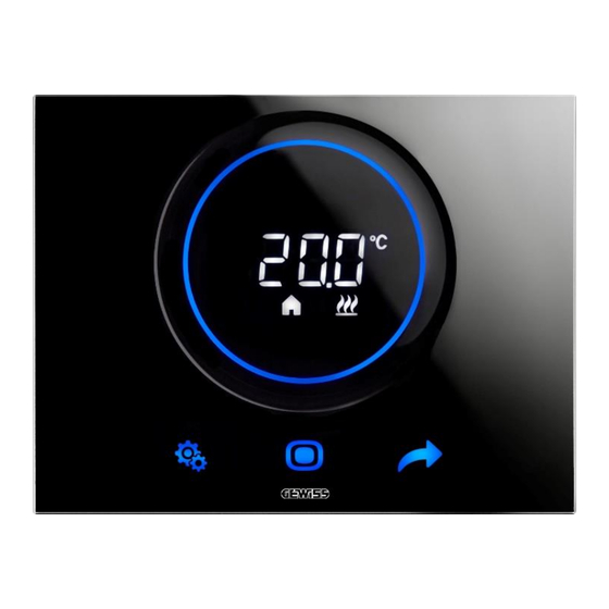
Page 14: The Thermostat
The thermostat The device is made up of two main elements: a base, fixed to the wall or to a 3-gang rectangular box, and a front part coupled with the base and attached to it by means of a screw. It is a LED backlit touch device. - Page 15 UNCTIONS Change active mode Mode / Enter Confirm parameter to be changed Display next page Display next parameter to be changed Next Display next parameter value 1. SET menu activation: change the device parameters Display the previous or next value of the parameter to be changed ...
- Page 16 REATING A NEW ACCOUNT AND ASSOCIATING THE THERMOSTAT WITH THE APP page 16 | T | PROGRAMMING MANUAL HERMO...
-
Page 17: Creating An Account And Associating The Thermo Ice Wi-Fi
Creating a new account on the app After wiring the thermostat and fixing it to the wall, as explained in the installation manual supplied with the device (also available at www.gewiss.com), access the app (Thermo ICE 2.0) that enables the remote control of the thermostat. - Page 18 Scroll down the page, giving consent where necessary, then click on the tick Open the e-mail address you indicated during the registration phase Check the incoming post. There should be an e-mail confirming the registration (if there isn't, check the “Spam”...
-
Page 19: Associating The Thermo Ice Wi-Fi
Associating the Thermo ICE Wi-Fi In the app, select the “Configure new Thermo ICE” option Choose which of the three configuration modes you want to use. The three possibilities are: WPS configuration ESP Touch configuration Wi-Fi configuration The configuration mode recommended by the manufacturer is WIFI, but ESP Touch or WPS can be used if WIFI is not available. -
Page 20: Wi-Fi Configuration
WI-FI CONFIGURATION ANDROID PROCEDURE: 1. Open the Thermo Ice app 2. Click on the “+” button 3. The “Thermo ICE search” page will open. Click on “Configure new Thermo ICE” 4. A drop-down menu allows you to choose one of the three possible configuration modes. Select “Wi-Fi configuration”... - Page 21 6. Activate the thermostat 7. Keep the Set button key pressed for at least 15 seconds. The key will turn green 8. The screen will show “P 1”, which stands for “Advanced parameter 1”. This is the procedure for accessing the advanced thermostat parameters button key, or the circular slider, to find parameter “P 21”...
- Page 22 15. You will now see a new page, that needs to be filled in 16. Enter the password to access the selected Wi-Fi network 17. The default code is WPA/WPA2 18. Now click on the tick NAME OF THE WI-FI NETWORK SELECTED PASSWORD OF THE...
- Page 23 21. At the end of the procedure, an info message will appear on the screen to tell you that the configuration has been successfully completed 22. Once the association has been completed, the thermostat will show the word “donE” 23. The thermostat display quits the advanced parameters area and returns to the initial page 24.
- Page 24 26. Click on the name of the newly configured thermostat. A new page will open 27. This page shows the systems available. Click on the name of the system that you want to associate the thermostat with. If no system has yet been created, click on “Create new system”;...
- Page 25 4. A drop-down menu allows you to choose one of the three possible configuration modes. Select “Wi-Fi configuration” 5. An info message will appear on the screen. Click on OK 6. Activate the thermostat 7. Keep the Set button key pressed for at least 15 seconds.
- Page 26 button key, or the circular slider, to find parameter “P 21” 9. Use the Next 10. Use the Mode button key to access the parameter P21 menu 11. Select the value 1 using the Next button key or the circular slider. Confirm with the Mode button key 12.
- Page 27 19. You will now see a page showing all the networks that are available. Select the network generated by the thermostat itself (identified by the name “GWTHERMOICEX_YYXX) 20. Quit the “Settings” page and return to the app 21. An info message will appear, telling you that the configuration has been successfully completed.
- Page 28 22. Once the association has been completed, the thermostat display will show the word “donE” 23. The thermostat display quits the advanced parameters area and returns to the initial page 24. The app returns to the “Thermo ICE search” page, showing the newly configured thermostat 25.
-
Page 29: Esp Touch Configuration
27. On the page that shows the thermostats associated with the app, the newly associated thermostat will appear 28. The configuration procedure is now complete ESP TOUCH CONFIGURATION ANDROID PROCEDURE: 1. Connect your smartphone to the domestic Wi-Fi network that Thermo ICE must connect to 2. - Page 30 6. An info message will appear on the screen. Click on OK 7. You will now see a page showing the name of the Wi-Fi network that Thermo ICE will connect to (the same one that your smartphone is already connected to); enter the network access password in the relative field page 30 | T | PROGRAMMING MANUAL...
- Page 31 8. Now click on the tick 9. Activate the thermostat 10. Keep the Set button key pressed for at least 15 seconds. The key will turn green 11. The screen will show “P 1”, which stands for “Advanced parameter 1”. This is the procedure for accessing the advanced thermostat parameters button key, or the circular slider, to find parameter “P 21”...
- Page 32 19. The app returns to the “Thermo ICE search” page, showing the newly configured thermostat 20. Click on the thermostat to assign it a name. A new page will open. Enter the name you want to give the thermostat in the relative field page 32 | T | PROGRAMMING MANUAL HERMO...
- Page 33 21. Once the name has been assigned, you will see a page showing all the systems that are available. Click on the name of the system that you want to associate the thermostat with. If no system has yet been created, click on “Create new system”; you will see a new page, where you can assign a name to the system you want to create 22.
- Page 34 5. A drop-down menu allows you to choose one of the three possible configuration modes. Select “ESP Touch configuration” 6. An info message will appear on the screen. Click on OK page 34 | T | PROGRAMMING MANUAL HERMO...
- Page 35 7. You will now see a page showing the name of the Wi-Fi network that Thermo ICE will connect to (the same one that your smartphone is already connected to); enter the network access password in the relative field 8. Now click on the tick 9.
- Page 36 17. When the procedure has ended, the word “donE” will appear on the thermostat display. The thermostat display quits the advanced parameters area and returns to the initial page 18. The app returns to the “Thermo ICE search” page, where you can see the newly configured thermostat 19.
-
Page 37: Wps Configuration
21. The app returns to the initial page, showing the newly configured thermostat 22. The configuration procedure is now complete WPS CONFIGURATION ANDROID/IOS PROCEDURE: PRE-REQUISITES: OU WILL NEED A ROUTER THAT OFFERS MODE MODE MUST ALREADY HAVE BEEN ENABLED BEFORE BEGINNING THIS PROCEDURE 1. - Page 38 5. An info message will appear on the screen. Click on OK 12. Activate the thermostat 13. Keep the Set button key pressed for at least 15 seconds. The key will turn green 14. The screen will show “P 1”, which stands for “Advanced parameter 1”. This is the procedure for accessing the advanced thermostat parameters button key, or the circular slider, to find parameter “P 21”...
- Page 39 20. Wait for the configuration procedure to terminate 21. When the procedure has ended, the word “donE” will appear on the thermostat display 22. The app returns to the “Thermo ICE search” page, where you can see the newly configured thermostat 23.
-
Page 40: Main Page Of The App, And Standard Remote Commands
Main page of the app, and standard remote commands Once the app has been installed and associated with the thermostat, this is the homepage that the user sees when the app is opened: UNCTION Indicator of the room temperature measured Indicator of the setpoint defined Indicator of the humidity percentage measured by the thermostat Indicator of the type of operation selected: Heating/Cooling... - Page 41 ASIC GUIDE TO USING THE THERMOSTAT AND THE APP CHORUS | T | page 41 HERMO...
-
Page 42: Basic Guide
10 Basic guide Once the app has been installed and associated with the thermostat, you can command the thermostat itself both locally and from a distance. 10.1 Thermostat operating mode The thermostat has six different operating modes: OMFORT Pre-defined setpoint; the OMFORT setpoint can be temporarily CONOMY... -
Page 43: Manual Temperature Regulation: Temporary Forcing
mode allows the required target temperature to be set at any time. ANUAL OFF mode only activates the systems when it is necessary to protect them, if the temperature reaches critical levels. 10.2 Manual temperature regulation: temporary forcing The user can modify the room temperature by temporarily forcing the setpoint (or by regulating the setpoint, if the thermostat is in M mode). -
Page 44: Switching From Heating To Cooling And Vice Versa
LOCAL COMMAND (THERMOSTAT) TAND LONE LAVE The possibility to select all six thermostat The choice of operating mode is limited to the operating modes (Comfort/Pre- predefined one, or OFF Comfort/Economy/Auto/Manual/OFF) Unlimited access to the advanced parameters (if No access to the parameters consent has been given via the app) Unlimited temporary forcing of the temperature Limited temporary forcing of the temperature... - Page 45 Activate the backlighting of the thermostat by bringing your hand close to it Select the page that shows the temperature, using the Next button key to move from one page to the next Press the Set command ...
- Page 46 Open the app on your mobile device Click on . The “Settings” page will open. AUTOMATIC Scroll down the page until you find the item “Advanced settings”. Click on “Advanced settings” A new page will open. Click on “Temperature control” page 46 | T | PROGRAMMING MANUAL HERMO...
- Page 47 On the page that opens, make sure the “Automatic switch” option is activated (the button key must be in the “ON” position). You can now set the dates for switching from type of operation to the other Click on “Start Heating” and “Start Cooling” to open a drop- down window with a calendar.
- Page 48 For a more detailed explanation of the various commands and functions, read the following chapters. page 48 | T | PROGRAMMING MANUAL HERMO...
- Page 49 TRUCTURE ORGANISATION AND LOGIC CHORUS | T | page 49 HERMO...
-
Page 50: Structure And Operation
11 Structure and operation When using and setting the thermostat, it's necessary to choose a series of operating types and modes, along with the role of the various users who can access it. The settings defined will affect how the user interacts with the thermostat, and the functions made available to him/her. -
Page 51: Type Of Control
11.1 Type of control The thermostat has two different types of control. The choice is made via the “Thermostat operation” parameter, which can only be accessed and modified from the app: Stand-Alone Slave TYPE OF CONTROL TAND LONE LAVE This mode gives the user complete control of the This mode gives limited thermostat control. -
Page 52: Where To Set The "Type Of Control " In The App
Only Administrators can alter the parameters. Access to the temperature adjustment profiles is permitted for Administrators in read/write mode, but is not permitted for Base Users. Limit-free humidity management is available to Administrators, whereas Base Users cannot access the parameter modification section. - Page 53 You will now see a page where you can choose whether to set the thermostat in “Standalone” or “Slave” mode CHORUS | T | page 53 HERMO...
-
Page 54: Type Of User
11.2 Type of user Two different types of user can be set: Administrator Base User Each type has a different command scope and functions. In general, the Administrator has full access to all the thermostat functions and regulations via the app. In addition, he/she has the power to register new users and define which role to assign to them (new Administrator or new Base User). - Page 55 In the menu that appears, select “Invite a new user”. The “Invite a new user” page will open. Enter the e-mail address of the user you are inviting in the relative space CHORUS | T | page 55 HERMO...
- Page 56 After entering the e-mail, you can decide whether to make this user a Base User or an Administrator The user will receive an e-mail at the address indicated, as notice of the procedure; if he/she is not already registered, this must be done before accessing the app ...
-
Page 57: Type Of Operation
11.3 Type of operation The thermostat can be used with two different functions: Heating Cooling The Heating function is usually used in winter, and the Cooling function in summer. The type of function (Heating/Cooling) can be set locally or from a distance. Locally, it's managed via the local navigation menu, using the Heat/Cool parameter that allows you to switch between the two types. -
Page 58: Where To Set The Temperature Adjustment Control Logic Locally
4. Find the “Temperature control logic” item; click on it to open a drop-down menu containing four items: Heating only Cooling only 2 pipes on relay 1 4 pipes on relays 1 and 2 The thermostat must be set on one of the last two items: WHERE TO SET THE TEMPERATURE ADJUSTMENT CONTROL LOGIC LOCALLY (In order to set the control logic locally, advanced parameter access must be enabled via the app and the thermostat must be set as Stand-Alone.) -
Page 59: In The App
UMMARY OF VALUES FOR PARAMETER Heating only, on relay 1 Cooling only, on relay 1 Heating + Cooling, 2 pipes on relay 1 Heating + Cooling, 4 pipes on relay 1- heating / relay 2 - cooling 7. Using the circular slider or the Next button key , choose the value corresponding to the required configuration 8. - Page 60 page 60 | T | PROGRAMMING MANUAL HERMO...
-
Page 61: Set The Dates For Automatic Heating /Cooling Switchover Via The App
11.3.3 S ET THE DATES FOR AUTOMATIC EATING OOLING SWITCHOVER VIA THE APP If you are an Administrator, you can pre-set the activation dates for the two types of operation via the app so that the thermostat can switch from one to the other automatically. In order for this to happen, the operating mode must be AUTOMATIC Attention: the dates are not stored by the thermostat but only in the cloud, which handles the change in... - Page 62 On the page that opens, make sure the “Automatic switch” option is activated (the button key must be in the “ON” position). You can now set the dates for switching from type of operation to the other Click on “Start Heating” and “Start Cooling” to open a drop-down window with a calendar. The item on the left contains the days of the month, whereas the one on the right shows the months of the year.
- Page 63 CHORUS | T | page 63 HERMO...
-
Page 64: Operating Modes
11.4 Operating modes The thermostat has six different operating modes: OMFORT Pre-defined setpoint; the OMFORT setpoint can be temporarily CONOMY forced UTOMATIC The setpoint cannot be forced Free setpoint ANUAL Each mode has different operating parameters and functions. mode is used when there are people in the room where the thermostat is installed. It is OMFORT therefore the one that offers the most comfortable temperature levels possible: in Heating, the highest temperature of all those envisaged in the five operating modes with a predefined setpoint, and in Cooling... - Page 65 The temperature adjustment profiles are divided into “Winter profile” and “Summer profile”. The activation of one or the other depends on the dates set on the “Temperature control” page (see ch. 11.1.3.1) Click on one of the two items to open a page where the Administrator can set the temperature adjustment profiles for each day of the week.
- Page 66 This tool allows you to enter up to 8 different intervals for each day of the week Use the pencil to alter or remove an unwanted interval Days of the week To copy the hourly programming of one day of the week onto another day, select icon in the lower bar and then the Copy day item;...
- Page 67 Attention: the profiles can only be copied if the user is associated with at least two systems. Otherwise, when you press on “Copy profile” the following warning will appear on the screen: The last HVAC mode is OFF. This only purpose of this mode is to safeguard the systems from any possible damage caused by extreme temperatures.
-
Page 68: Setting The Operating Modes Locally
Operating mode: Manual 10°C ≤ ≤ 35°C manual HEATING/ COOLING and it must respect these rules: Operating mode: M ANUAL ≤ T building protection operation HEATING ≤ T operation building protection COOLING In heating mode, the setpoint cannot be lowered as far as the setpoint defined to protect the building from low temperatures (T ). -
Page 69: Where To Select The Operating Mode In The App
STAND-ALONE SLAVE All the modes can be selected, PERATING MODE SET OFF / pre-set mode using the Mode button key LOCALLY The user can always temporarily force the setpoint, whatever the operating mode; the exceptions are OFF mode and mode. In the first case, the setpoints cannot be modified as only anti-freeze and MANUAL high temperature protection are active. - Page 70 UTOMATIC MODE ANUAL MODE OMFORT MODE page 70 | T | PROGRAMMING MANUAL HERMO...
- Page 71 COMFORT MODE CONOMY MODE MODE CHORUS | T | page 71 HERMO...
-
Page 72: How To Change The Setpoint Regulation Interval For Manual , Economy , Pre -Comfort And Comfort Modes With Slave Control
11.4.3 H OW TO CHANGE THE SETPOINT REGULATION INTERVAL FOR ANUAL CONOMY OMFORT AND OMFORT MODES WITH LAVE CONTROL The Administrator can use the app to alter the setpoint regulation interval for the ECONOMY (temporary setpoint forcing) and operating modes when the thermostat is COMFORT COMFORT MANUAL... -
Page 73: Regulation Of The Hvac Mode Setpoints Via App
The control type must be set as “Slave” In the item “Temporary setpoint forcing – Range of adjustment”, click on the pencil A menu will open, where you can regulate the manual setpoint regulation interval within a range from 0.5°... - Page 74 In particular: Operating mode: Comfort/Pre-comfort/Economy/OFF ≤ T ≤ T ≤ T HEATING anti-freeze economy pre-comfort comfort ≤ T ≤ T ≤ T comfort pre-comfort economy high temperature COOLING protection Operating mode: Comfort/Pre-comfort/Economy ≤ T ≤ T ≤ T ≤ 10°C 35°C HEATING economy...
- Page 75 The setpoints are divided into two groups: for Heating and for Cooling . Click on each item to open a drop-down menu where you can regulate (within the permitted interval) the setpoint for each operating mode and protection threshold. EATING FREEZE EATING...
-
Page 76: Local Regulation Of The Comfort , Pre -Comfort And Economy Mode Setpoints
OOLING OMFORT OOLING IGH TEMPERATURE PROTECTION Note that an interval is associated with each setpoint (e.g. ). This indicates the temperature range within which the setpoint can be regulated. The interval start and end points are determined by the need to respect the hierarchical order mentioned previously. 11.4.5 L OCAL REGULATION OF THE OMFORT... -
Page 77: Local Regulation Of The Building Protection Setpoints
11.4.6 L OCAL REGULATION OF THE BUILDING PROTECTION SETPOINTS The building protection setpoints can also be modified locally if access to the advanced parameters has been enabled via the app and the thermostat status is Stand-Alone. Activate the backlighting of the thermostat ... -
Page 78: Control Algorithms
11.5 Control algorithms The thermostat can regulate its own operation (and, consequently, system management) on the basis of two different control algorithms stored inside it. These algorithms are: 2 points ON-OFF Proportional-integral with PWM control CONTROL ALGORITHM SUMMARY OF THE CHARACTERISTICS This type of control involves the turning on and off of the temperature adjustment system following a hysteresis cycle. -
Page 79: Where To Set The Control Algorithm On The App
Use the Mode button key to select parameter P4. There are two values, each corresponding to one of the two algorithms: UMMARY OF VALUES FOR PARAMETER 2 points ON-OFF PWM proportional-integral Use the circular slider or the Next button key to pass from one value to the other (i.e. - Page 80 page 80 | T | PROGRAMMING MANUAL HERMO...
- Page 81 EOFENCING CHORUS | T | page 81 HERMO...
-
Page 82: Automatic Presence Detection - Geofencing
12 Automatic presence detection - Geofencing The app allows the user to activate the geofencing function. This function influences the behaviour of the thermostat on the basis of the user's position, programming automatic actions when he/she enters or leaves the home. A perimeter is defined around the home, and used by the device to understand when the user is at home or in the immediate vicinity, and when he/she is "outside";... -
Page 83: Enabling Geofencing Via The App
Scroll down the page until you find the item “Privacy”. Select this item The “Privacy” page will open. Select the item “Location services” The “Location services” page will open. Make sure the command is active 12.2 Enabling Geofencing via the app The enabling/disabling and limitation of the Geofencing function can only be done by an Administrator. - Page 84 Scroll down the “Advanced settings” page until you find the item “Geofencing” Select “Geofencing settings”. The “Geofencing” page will open Under the item “Activation”, you can choose from three different options: Disabled Administrators only (Administrator) ...
-
Page 85: Activating Geofencing On Your Account
Disabled = Geofencing disabled Administrators only = Geofencing enabled for Administrators only All users = Geofencing enabled for all users Select the second option if you want to activate geofencing for Administrators only; select the third if you want to enable Base Users as well 12.3 Activating Geofencing on your account Once geofencing has been enabled, it must be activated on your account before it can be used. - Page 86 Scroll down the “Advanced settings” page until you find the item “Geofencing settings” Select “Geofencing settings”. The “Geofencing” page will open page 86 | T | PROGRAMMING MANUAL HERMO...
-
Page 87: Setting The Actions For Entering And Leaving The Geofencing Area
At the bottom of the page you will find the parameter “Enable this device to the use of geofencing”. Move the push-button to “ON” to activate geofencing on your mobile device 12.4 Setting the actions for entering and leaving the geofencing area The aim of geofencing is to influence the behaviour of the thermostat on the basis of the user's position, programming automatic actions when he/she enters or leaves the home. - Page 88 Scroll down the “Advanced settings” page until you find the item “Geofencing settings” Select “Geofencing settings”. The “Geofencing” page will open Under the item “Activation”, you will find two different commands: “Action on arriving at home” ...
-
Page 89: Setting The Geofencing Area Radius
The user must first of all choose whether to prevent the thermostat from taking any action on entering and/or leaving, or set an operating mode. After defining whether or not the thermostat must take an action, in the second case it's then necessary to decide which operating mode must be set. - Page 90 sooner than the physical entry of the user in the home; if the area is narrower, the operating mode will be activated later. The geofencing area can be altered within an interval from min. 100 metres to max. 3000 metres. To set the extension of the geofencing area, proceed as follows: ...
- Page 91 After defining the required extension of the geofencing area, click on the tick CHORUS | T | page 91 HERMO...
- Page 92 UMIDITY page 92 | T | PROGRAMMING MANUAL HERMO...
-
Page 93: Humidity
13 Humidity The thermostat is fitted with an internal sensor for measuring the relative humidity in the room. You can control room humidification or dehumidification directly, via relay 2. The advanced reference parameter is P11 – “Humidity management”. It can be regulated either locally or via the app. - Page 94 The “Advanced settings” page will open Under the item “Temperature control logic”, you can choose which configuration to use the relays in. There are four possibilities: Heating only Cooling only 2 pipes on relay 1 ...
-
Page 95: Setting Humidity Control Via The App
SETTING HUMIDITY CONTROL VIA THE APP Open the app on your mobile device Click on The “Settings” page will open. Scroll down the page until you find the item “Advanced settings”. Select this item The “Advanced settings” page will open ... - Page 96 The “Humidity control” page will open. Under the item “Humidity control” there are three items: Off Humidity increase Humidity reduction Select one of the last two items to gain access to the advanced humidity parameters This advanced parameter can only be accessed if the thermostat is set as Stand-Alone and the advanced parameters have been enabled via the app Advanced parameter P11 offers three different values, as shown below: UMMARY OF VALUES FOR PARAMETER...
-
Page 97: How To Regulate The Advanced Humidity Parameters Locally
13.1 How to regulate the advanced humidity parameters locally This advanced parameter can only be accessed if the thermostat is set as Stand-Alone and the advanced parameters have been enabled via the app Activate the backlighting of the thermostat ... - Page 98 The “Advanced settings” page will open Under the item “Controls”, select “Humidity control” Under the item “Other”, you will find “Humidity sensor – Correction factor”. Select this item to see a drop-down menu showing the possible correction values. The interval ranges from -10% to +10% page 98 | T | PROGRAMMING MANUAL...
-
Page 99: Local Activation/Deactivation Of Humidification/Dehumidification
13.3 Local activation/deactivation of humidification/dehumidification This advanced parameter can only be accessed if the thermostat is set as Stand-Alone and the advanced parameters have been enabled via the app Activate the backlighting of the thermostat Use the Next button key to select the page showing the relative humidity ... -
Page 100: Activating/Deactivating Humidification/Dehumidification Via The App
13.4 Activating/deactivating humidification/dehumidification via the app See “Setting humidity control via the app”. 13.5 Local regulation of the humidity threshold If advanced parameter P11 has been set with a value of 1 or 2, the user can access the basic parameters “Humidity threshold”... - Page 101 The “Advanced settings” page will open Under the item “Controls”, select “Humidity control” The “Humidity control” page will open. Under the item “Humidity control” you will find the option “Humidity threshold”, with the currently set value on the right CHORUS | T | page 101 HERMO...
-
Page 102: Local Regulation Of The Humidity Threshold Hysteresis
Select the pencil on the right-hand side of the option to open a drop-down menu where you can regulate the humidity threshold. You can enter a value within an interval from 20% to 80%. The scale is in 5% steps (i.e. not continuous) 13.7 Local regulation of the humidity threshold hysteresis If advanced parameter P11 has been set with a value of 1 or 2, the user can access the basic parameters “Humidity threshold”... -
Page 103: Regulating The Humidity Hysteresis Via The App
to move on to the next page. The message “HYSt” will appear on Use the Next button key the screen Use the Mode button key to access the parameter in question The currently active hysteresis value will appear on the screen ... - Page 104 The “Advanced settings” page will open Under the item “Controls”, select “Humidity control” The “Humidity control” page will open. Under the item “Humidity control” you will find the option “Humidity threshold hysteresis” On the right-hand side of this item, you can see the hysteresis value currently active. Next to it, there is a pencil .
- Page 105 UXILIARY TEMPERATURE SENSOR CHORUS | T | page 105 HERMO...
-
Page 106: External Temperature Sensor
14 External temperature sensor The device is fitted with an input contact for connecting an NTC external temperature sensor. Parameter P18: Enabling of auxiliary input for temperature sensor is used to configure the input of the auxiliary sensor so that a wired NTC temperature sensor (GW10800) or a flush-mounting one (GW1x900) can be connected to measure the room temperature or the floor-level temperature. -
Page 107: Enabling The Auxiliary Input Via The App
UMMARY OF VALUES FOR PARAMETER Disabled Enabled for GW1x900 Enabled for GW10800 Enabled for GW10800 (floor) Select the value corresponding to the external sensor you want to install Confirm with the Mode button key Click on Set to quit the advanced parameters area 14.2 Enabling the auxiliary input via the app ... - Page 108 Click on “Temperature control” to open the relative page Under the item “Auxiliary input” you will find a window showing the current setting for the auxiliary input. Click on it to open a drop-down menu showing the four possible configurations: UXILIARY INPUT Disabled Room temperature measurement with GW1x900...
-
Page 109: Local Regulation Of The Incidence Of The Auxiliary Sensor (P19)
14.3 Local regulation of the incidence of the auxiliary sensor (P19) This advanced parameter can only be accessed if the thermostat is set as Stand-Alone and the advanced parameters have been enabled via the app. In addition, advanced parameter P18 must be set on “Room temperature GW1x900”... - Page 110 Scroll down the “Advanced settings” page until you find the item “Temperature control” Click on “Temperature control” to open the relative page Under the item “Auxiliary input”, if the Room temperature GW1x900” or “Room temperature GW10800” option is selected, beneath the relative window you will find the item: “Incidence of the external temperature sensor in the measured temperature calculation”, with the corresponding value shown on the right page 110 | T...
-
Page 111: Local Regulation Of The Floor Temperature Alarm Threshold (P20)
Click on the pencil to see a drop-down menu where you can regulate the incidence of the auxiliary temperature sensor in the weighted average made to determine the overall temperature value. The value can be selected within an interval from 10% to 100% ... -
Page 112: Regulating The Floor Temperature Alarm Threshold Via The App
Proceed as follows: Activate the backlighting of the thermostat Use the Next button key to select the page showing the temperature Press and hold the Set button key until the code P1 appears on the screen Use the circular slider or the Next button key to find advanced parameter P20 ... - Page 113 Scroll down the “Advanced settings” page until you find the item “Temperature control” Click on “Temperature control” to open the relative page Under the item “Auxiliary input”, if the “Floor temperature measurement with GW10800” option is selected, underneath you will find the item: “Floor alarm threshold temperature”, with the corresponding value shown on the right CHORUS | T | page 113...
- Page 114 Click on the pencil to see a drop-down menu where you can regulate the floor temperature alarm threshold. The value can be selected within an interval from 15°C to 100°C When you quit the settings area, you will be asked whether you want to save the changes made. Click on “Yes”...
- Page 115 ISPLAY REGULATION Lighting intensity Proximity sensor activation/deactivation Standby activation/deactivation Audio activation/deactivation Time regulation Day regulation CHORUS | T | page 115 HERMO...
-
Page 116: Backlighting, Proximity Sensor, Standby
15 Backlighting, proximity sensor, standby The thermostat screen is backlit, and the colour of the commands and circular slider can change according to the type of operation (Heating/Cooling), type of control (Stand-Alone/Slave) and type of function (single or long touch on the command). OLOURS OF THE COMMAND BUTTON KEYS Single touch Long touch –... - Page 117 Apart from the item “Measurement unit”, there is also: Display Standby Audio CHORUS | T | page 117 HERMO...
-
Page 118: Regulating The Lighting Intensity Of The Screen
15.2 Regulating the lighting intensity of the screen Under the item “Display”, you will find “backlighting intensity %” Press on this item to open a drop-down menu where you can regulate the intensity of the backlighting (interval permitted: 30 – 100%) 15.2.1 P ROXIMITY SENSOR ACTIVATION DEACTIVATION... -
Page 119: Standby Activation / Deactivation
15.2.2 S TANDBY ACTIVATION DEACTIVATION On the “Display and audio settings” page, underneath the “Standby” item, there is a command for activating and deactivating standby mode The item “Energy saving. Switch-off display in standby” allows you to switch the screen off completely when it's not being used. -
Page 120: Setting The Thermostat Display Locally
15.3 Setting the thermostat display locally You can regulate the lighting intensity, and activate/deactivate the proximity sensor, standby and audio signal locally if the thermostat status is Stand-Alone and access to the advanced parameters has been enabled via the app by the Administrator. 15.3.1 R EGULATING THE LIGHTING INTENSITY OF THE SCREEN ... -
Page 121: Tandby Activation Deactivation
15.3.3 S TANDBY ACTIVATION DEACTIVATION 15.3.3.1 V IA THE ADVANCED PARAMETER Activate the backlighting of the thermostat Select the thermostat page showing the temperature Press and hold the Set button key until the code P1 appears on the screen ... -
Page 122: Audio Activation / Deactivation
15.3.4 A UDIO ACTIVATION DEACTIVATION Activate the backlighting of the thermostat Select the thermostat page showing the temperature Press and hold the Set button key until the code P1 appears on the screen Using the circular slider or the Next button key , scroll through the advanced parameters until you find parameter P16 ... -
Page 123: Regulating The Time Shown On The Thermostat
15.4 Regulating the time shown on the thermostat If standby mode is active, the thermostat screen will alternately show the measured temperature, humidity percentage and current time. The date and time are regularly updated thanks to the connection with the server. If you need to alter these data however, you can do it locally (as long as access to the basic or advanced parameters has been enabled via the app). - Page 124 There are seven possible values, each representing a day of the week: UMMARY OF THE VALUES REPRESENTING THE DAYS OF THE WEEK Sunday Monday Tuesday Wednesday Thursday Friday Saturday Use the circular slider or the Next button key to select the value corresponding to the current day ...
- Page 125 SAGE STATISTICS CHORUS | T | page 125 HERMO...
-
Page 126: Usage Statistics
16 Usage statistics The Thermo Ice WiFi app allows you to graphically view the temperature and humidity levels and the percentage of system activation in heating/cooling over time, as registered on the cloud. This function offers you immediate visual feedback about the behaviour of the thermostat. To view the usage statistics, carry out the following steps: 1. - Page 127 6. You will see a page showing the following chart. There are three variables: a. Temperature b. Humidity c. Switch-on operations The temperature curve shows the various temperature values measured by the thermostat sensor in the period in question. The humidity curve shows the various humidity levels registered by the thermostat sensor in the period in question.
- Page 128 On the line at the bottom of the page, you can choose the day, week, month or year that you want to see. Use the two arrows on the right and left to move to the day, week, month or year before/after the one shown in that moment.
- Page 129 Press and hold on a certain point of the chart to see the exact values registered in that point. CHORUS | T | page 129 HERMO...
- Page 130 AINTENANCE page 130 | T | PROGRAMMING MANUAL HERMO...
-
Page 131: Maintenance
17 Maintenance The user may need to clean the plate if it gets dirty. There is a special function that allows you to do this without accidentally altering the thermostat settings. 17.1 Cleaning the plate This function temporarily inhibits the capacitive sensors so you can clean the surface of the plate without accidentally modifying the thermostat settings. - Page 132 ELETING A SYSTEM EMOVING USERS page 132 | T | PROGRAMMING MANUAL HERMO...
-
Page 133: Deleting A System
18 Deleting a system To delete a system from the list of devices associated with your app, proceed as follows: Open the app on your mobile device Use the button key to open the page listing the devices associated with the app ... - Page 134 page 134 | T | PROGRAMMING MANUAL HERMO...
- Page 135 ESETTING THE FACTORY CONDITIONS CHORUS | T | page 135 HERMO...
-
Page 136: Resetting The Factory Conditions
20 Resetting the factory conditions If you need to reset the thermostat with its original factory conditions, proceed as follows: Press the Next button key for 10 seconds The screen will show a numerical value indicating the firmware version installed on the thermostat ... - Page 137 ARAMETERS BASIC AND ADVANCED CHORUS | T | page 137 HERMO...
-
Page 138: Parameters: Basic And Advanced
21 Parameters: basic and advanced Thermostat operation is governed by a series of parameters that can be activated/deactivated and regulated by the user. Depending on the settings defined via the app, these parameters may be enabled or disabled, enabled for Administrators only, accessible or not accessible locally. Local access to the basic and advanced parameters must be enabled by an Administrator via the app. -
Page 139: Basic Parameters
Under the item “Local menu access” you will find three possible options: Disabled Basic parameters All parameters If “Disabled” is selected, you cannot access either basic or advanced parameters locally. If “Basic parameters” is selected, you can access only the basic parameters locally. If “All parameters”... -
Page 140: Advanced Parameters
HERMOSTAT PAGE HUMIDITY ASIC PARAMETERS Humidity threshold Hysteresis HERMOSTAT PAGE CLOCK ASIC PARAMETERS Hour Minutes From the temperature page, you can therefore define the setpoints for the C OMFORT OMFORT operating modes. You can also decide whether the thermostat should be used in Heating or CONOMY Cooling mode (see 11.1.4.5.). -
Page 141: Advanced Parameter P1
Temperature measurement unit °C/°F Backlighting intensity regulation Display deactivation in standby Temperature/Humidity/Time visualisation P14 = ON Audio signal Proximity sensor Enabling of the auxiliary sensor for temperature sensor Auxiliary sensor incidence in measured P18 = 0, 1, 2 temperature calculation Floor temperature alarm threshold P18 = 3 Wi-Fi configuration mode... -
Page 142: Dvanced Parameter P5
UMMARY OF VALUES FOR PARAMETER 2 points ON-OFF PWM proportional-integral 21.2.6 A DVANCED PARAMETER This parameter is used to alter the value of the regulation differential for the 2-point control algorithm of the type of operation active (H or C). It is visible if the current value of advanced parameter P4 is “2 points ON-OFF”... -
Page 143: Dvanced Parameter P10
21.2.10 A DVANCED PARAMETER This parameter is used to correct the value measured by the humidity sensor on the device. UMMARY OF VALUES FOR PARAMETER -10% < < 10% 21.2.11 A DVANCED PARAMETER This parameter is used to enable or disable humidification or dehumidification. For this parameter to be visualised and accessible, the “Temperature adjustment control logic”... -
Page 144: Dvanced Parameter P16
21.2.16 A DVANCED PARAMETER This parameter is used to enable or disable the audio signal that accompanies the pressing of button keys. UMMARY OF VALUES FOR PARAMETER Disabled Enabled 21.2.17 A DVANCED PARAMETER This parameter is used to enable the proximity sensor on the device. If enabled, the backlighting comes on when the sensor detects that someone is near the device;... -
Page 145: Advanced Parameter P22
NB: the default setting of the new thermostat allows the advanced parameters to be accessed. If, for any reason, this is not the case, reset the original factory conditions of the thermostat. 21.2.22 A DVANCED PARAMETER This parameter is used to activate or deactivate the radio module (Wi-Fi). UMMARY OF VALUES FOR PARAMETER Disabled Enabled... - Page 146 page 146 | T | PROGRAMMING MANUAL HERMO...
Need help?
Do you have a question about the CHORUSMART GW16970CB and is the answer not in the manual?
Questions and answers