Table of Contents
Advertisement
2022
WARNING
Improper installation, adjustment, alteration, ser
vice or maintenance can cause property damage,
personal injury or loss of life. Installation and ser
vice must be performed by a licensed professional
HVAC installer or equivalent, service agency, or the
gas supplier
CAUTION
As with any mechanical equipment, contact with
sharp sheet metal edges can result in personal in
jury. Take care while handling this equipment and
wear gloves and protective clothing.
Table Of Contents
. . . . . . . . . . . . . . . . . . . . . . . . . . . . . . . . .
. . . . . . . . . . . . . . . . . . . . . . . . .
. . . . . . . . . . . . . . . . . . . .
. . . . . . . . . . . . . . . . . . . . . . . . . . . . . . . . . . . .
. . . . . . . . . . . . . . . . . . . . . . . . . . . . . . . . . . . . .
. . . . . . . . . . . . . . . . . . . . . . . . . . . . . . . .
. . . . . . . . . . . . . . . . . . . . . . . . . . . .
. . . . . . . . . . . . . . . . . . . . . . .
. . . . . . . . . . . . . . . . . . . . . . . . . .
. . . . . . . . . . . . . . . . . . . . . . . . .
. . . . . . . . . . . . . . . . . . . . .
. . . . . . . . . . . . . . . . . . . . . . . . .
. . . . . . . . . . . . . . . . . . . . . . .
. . . . . . . . . . . . . . . . . . . . . . . . . . . . . .
RETAIN THESE INSTRUCTIONS FOR FUTURE REFERENCE
Page 2
Page 3
Page 4
Page 4
Page 4
Page 5
Page 6
Page 6
Page 6
Page 8
Page 9
Page 9
Page 9
Page 11
. . . . . . . . . . . .
Page 11
INSTALLATION
INSTRUCTIONS
KGC/KCC092
KGC/KCC102
KGC/KCC120
KGC/KCC150
GAS AND COOLING PACKAGED UNITS
507118-13
8/2022
Supersedes 507118-12
. . . . . . . . . . . . . . . . . . . . . . . . . . . .
. . . . . . . . . . . . . . . . . . . . . . . . . . .
. . . . . . . . . . . . . . . . . . . . . . . .
. . . . . . . . . . . . . . . . . . . . . . . . . . . . . . . . . . . .
To prevent serious injury or death:
1-
Lock-out/tag-out before performing maintenance.
2-
If system power is required (e.g., smoke detector mainte
nance), disable power to blower, remove fan belt where
applicable, and ensure all controllers and thermostats are
set to the "OFF" position before
performing maintenance.
3-
Always keep hands, hair, clothing, jewelry, tools, etc.,
away from moving part
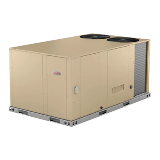
KGC SHOWN
(7.5 Ton)
(8.5 Ton)
(10 Ton)
(12-1/2 Ton)
Page 18
Page 26
. . . . . . . . . . . .
Page 27
Page 27
. . . . . . . . . . . . . . . . . . .
Page 28
. . . . . . . .
Page 31
Page 32
s.
Advertisement
Table of Contents

Related Manuals for Lennox KGC092


Summary of Contents for Lennox KGC092
-
Page 1: Table Of Contents
2022 INSTALLATION INSTRUCTIONS WARNING Improper installation, adjustment, alteration, ser KGC/KCC092 vice or maintenance can cause property damage, (7.5 Ton) personal injury or loss of life. Installation and ser KGC/KCC102 vice must be performed by a licensed professional (8.5 Ton) HVAC installer or equivalent, service agency, or the KGC/KCC120 gas supplier (10 Ton) -
Page 2: Dimensions
KG/KC 092, 102, 120, & 150 DIMENSIONS - Gas heat section shown 6-1/8 5-5/8 BOTTOM SUPPLY (143) (156) AIR OPENING 6-1/8 10-3/4 (156) (610) (711) (273) (508) (686) 60-1/8 (1527) BASE BOTTOM RETURN BOTTOM AIR OPENING POWER ENTRY 5-1/2 (140) Dia. 6-5/8 7 (178) (168) -
Page 3: Parts Arrangements
KG 092, 102, 120, & 150 PARTS ARRANGEMENT REHEAT EVAPORATOR BLOWER FILTERS COIL BLOWER CONDENSER COIL MOTOR (FOUR - 20 X 25 X 2”) FANS ECONOMIZER CONDENSER (OPTIONAL, BEHIND COIL PANEL) BURNERS COMBUSTION AIR INDUCER GAS VALVE INVERTER CONDENSATE COMPRESSORS DRAIN KC 092, 102, 120, &... -
Page 4: Shipping And Packing List
Shipping and Packing List WARNING Package 1 of 1 contains: Electric shock hazard and danger of 1- Assembled unit explosion. Can cause injury, death or product or property damage. Turn off Check unit for shipping damage. Receiving party should gas and electrical power to unit before contact last carrier immediately if shipping damage is found. -
Page 5: Unit Support
If this unit has been used for heating or cooling of A-Downflow Discharge Application buildings or structures under construction, the following Roof Mounting with C1CURB conditions must be met or the warranty will be void: Make sure the cap over the unit bottom drain hole is S A room thermostat must control the unit. -
Page 6: Duct Connection
Duct Connection Condensate Drains Make drain connection to the 1” N.P.T. drain coupling All exterior ducts, joints and openings in roof or building provided on unit. walls must be insulated and weather-proofed with flashing and sealing compounds in accordance with Note - The drain pan is made with a glass reinforced applicable codes. - Page 7 7- From the back side of the unit, pull the drain pan Bottom Drain Connection coupling through the rear condensate opening. 1- Remove heat access door. See figure 5. 8- Replace the condensate drain mullion and reinstall 2- Remove filter access door. eight screws.
-
Page 8: Connect Gas Piping
Connect Gas Piping (Gas Units) BOTTOM ENTRY GAS PIPING THROUGH THE CURB Before connecting field-provided piping, check with gas MULLION BETWEEN company or authorities having jurisdiction for local code HEAT AND COMPRES requirements. When installing gas supply piping, length SOR SECTIONS of run from gas meter must be considered in determining 4”... -
Page 9: Pressure Test Gas Piping
Pressure Test Gas Piping (Gas Units) High Altitude Derate Locate the high altitude conversion sticker in the unit When pressure testing gas lines, the gas valve must literature bag. Fill out the conversion sticker and affix next be disconnected and isolated. Gas valves can be to the unit nameplate. - Page 10 TABLE 2 1- Route thermostat cable or wires from subbase to INVERTER UP-SIZING control box (refer to unit dimensions to locate bottom and side power entry). Factory-Installed Inverter HP Replacement Inverter HP IMPORTANT - Unless field thermostat wires are rated for maximum unit voltage, they must be routed away 7-1/2 from line voltage wiring.
-
Page 11: Unit Power-Up
C-Hot Gas Reheat Units Only If pressure differential is not observed or blower rotation is Units require a dehumidify demand to initiate operation. A not correct: 24V input at DH is required to energize reheat. A 2- Suction pressure must drop, discharge pressure standalone dehumidistat (A20) and/or a room thermostat must rise, and blower rotation must match rotation / energy management system with humidity sensing may... - Page 12 D-Determining Unit CFM 2- With all access panels in place, measure static pressure external to unit (from supply to return). IMPORTANT - Units equipped with an inverter are Blower performance data is based on static pressure factory-set to run the blower at full speed when there is a readings taken in locations shown in figure 15.
- Page 13 LOCATION OF STATIC PRESSURE READINGS INSTALLATIONS WITH DUCTWORK INSTALLATIONS WITH CEILING DIFFUSERS ROOFTOP UNIT ROOFTOP UNIT RETURN AIR READING LOCATION RETURN AIR READING RE RE SUPPLY SUPPLY LOCATION TURN TURN FIRST BRANCH OFF OF MAIN RUN MAIN DUCT RUN SUPPLY AIR SUPPLY AIR READING READING...
- Page 14 F-Check Belt Tension force below these values indicates undertensioned belt. A force above these values Overtensioning belts shortens belt and bearing life. indicates an overtensioned belt. Check belt tension as follows: MEASURE BELT TENSION 1- Measure span length X. See figure 17. 2- Apply perpendicular force to center of span (X) with enough pressure to deflect belt 1/64”...
- Page 15 BLOWER DATA 092S & 102S STANDARD EFFICIENCY BELT DRIVE BLOWER − BASE UNIT BLOWER TABLE INCLUDES RESISTANCE FOR BASE UNIT ONLY (NO HEAT SECTION) WITH DRY INDOOR COIL AND AIR FILTERS IN PLACE. FOR ALL UNITS ADD: 1 − Wet indoor coil air resistance of selected unit. 2 −...
- Page 16 BLOWER DATA 120S & 150S STANDARD EFFICIENCY − BASE UNIT BLOWER TABLE INCLUDES RESISTANCE FOR BASE UNIT ONLY (NO HEAT SECTION) WITH DRY INDOOR COIL AND AIR FILTERS IN PLACE. FOR ALL UNITS ADD: 1 − Wet indoor coil air resistance of selected unit. 2 −...
- Page 17 BLOWER DATA FACTORY INSTALLED BELT DRIVE KIT SPECIFICATIONS Nominal Maximum Drive Kit Number RPM Range 590 - 890 800 - 1105 795 - 1195 3.45 730 - 970 3.45 940 - 1200 3.45 1015 - 1300 5.75 900 - 1135 5.75 1040 - 1315 5.75...
-
Page 18: Cooling Start-Up
TABLE 4 MANUFACTURER'S NUMBERS DRIVE COMPONENTS DRIVE ADJUSTABLE SHEAVE FIXED SHEAVE BELT BROWNING NO. OEM PART NO. BROWNING NO. OEM PART NO. BROWNING NO. OEM PART NO. 1VP34x7/8 31K6901 AK61x1 100244-20 AX54 100245-25 1VP40x7/8 79J0301 AK59x1 31K6801 AX55 100245-26 1VP34x7/8 31K6901 AK46x1 100244-17... - Page 19 NOTE - System charging is not recommended below REFRIGERANT STAGES - 150 60_F (15_C). In temperatures below 60_F (15_C), the TUBE/FIN OD COIL charge must be weighed into the system. CONDENSER COIL (BOTH FANS ARE ENERGIZED STAGES 1 & 2 WITH A Y1 DEMAND) If weighing facilities are not available, or to check the charge, use the following procedure:...
- Page 20 TABLE 7 581125-01 KG/KC 092S Normal Operating Pressures - All-Aluminum Coil Outdoor Coil Entering Air Temperature 65 F 75 F 85 F 95 F 105 F 115 F Suct Disc Suct Disc Suct Disc Suct Disc Suct Disc Suct Disc (psig) (psig) (psig)
- Page 21 TABLE 8 581126-01 KG/KC 102S Normal Operating Pressures - All-Aluminum Coil Outdoor Coil Entering Air Temperature 65 F 75 F 85 F 95 F 105 F 115 F Suct Disc Suct Disc Suct Disc Suct Disc Suct Disc Suct Disc (psig) (psig) (psig)
- Page 22 TABLE 9 581127-01 KG/KC 120S Normal Operating Pressures - All-Aluminum Coil Outdoor Coil Entering Air Temperature 65 F 75 F 85 F 95 F 105 F 115 F Suct Disc Suct Disc Suct Disc Suct Disc Suct Disc Suct Disc (psig) (psig) (psig)
- Page 23 TABLE 10 581128-01 KG/KC 150S Normal Operating Pressures - All-Aluminum Coil Outdoor Coil Entering Air Temperature 65 F 75 F 85 F 95 F 105 F 115 F Suct Disc Suct Disc Suct Disc Suct Disc Suct Disc Suct Disc (psig) (psig) (psig)
- Page 24 D-Refrigerant Charge and Check - Fin/Tube Coil TABLE 11 581129-01 KGC/KCC092S Fin/Tube - W & W/O Reheat WARNING-Do not exceed nameplate charge under CIRCUIT 1 CIRCUIT 2 any condition. Outdoor Dis Dis Coil This unit is factory charged and should require no further Suction Suction charge...
- Page 25 Charge Verification - Approach Method - AHRI Testing E-Compressor Controls (Fin/Tube Coil Continued) 1. Using the same thermometer, compare liquid See unit wiring diagram to determine which controls are temperature to outdoor ambient temperature. used on each unit. Optional controls are identified on wiring diagrams by arrows at junction points.
-
Page 26: Gas Heat Start-Up
This unit is equipped with an automatic spark ignition Gas Heat Start-Up (Gas Units) system. There is no pilot. In case of a safety shutdown, FOR YOUR SAFETY READ BEFORE LIGHTING move thermostat switch to OFF and return the thermostat switch to HEAT to reset ignition control. -
Page 27: Heating Operation And Adjustments
5- Turn gas valve switch to OFF. See figure 20. On 3- Spark ignitor energizes and gas valve solenoid opens. Honeywell VR8305Q gas valves, turn the knob on the 4- Spark ignites gas, ignition sensor proves the flame gas valve clockwise to “OFF”. -
Page 28: Supply Air Inverter Start-Up
Inverter Start-Up LVC2 (A183) VFD CONTROL BOARD A-General VENTILATION Units provide three blower speeds. The blower will SPEED SWITCH operate at lower speeds when cooling demand is low and higher speeds when cooling demand is high. This results in lower energy consumption. See table 18 for detailed POWER unit operation. - Page 29 Set Low Speed Minimum Position 4- If there is no thermostat signal, troubleshoot back toward the thermostat. 1- Initiate a blower (G) only AND occupied demand from the room thermostat or control system. 5- Check the power LED on the board. See figure 22. 2- Set the ventilation speed switch on the VFD control board to “LO”.
- Page 30 TABLE 18 UNIT OPERATION Compressor Blower Speeds Econo Fans Heat T'Stat Humid. Reheat Sensor Valve Cool Cool Cool 1-Low 1-Hi Vent Heat 1 & 2 1 & 2 Occupied Unocc. Min (Vent) Closed Min Hi Closed Min Hi Closed Min Lo Closed Y1 + Y2 Min Lo...
-
Page 31: Hot Gas Reheat Operation And Start-Up
Check-Out Hot Gas Reheat Start-Up And Operation Test hot gas reheat operation using the following General procedure. Hot gas reheat units provide a dehumidifying mode of operation. These units contain a reheat coil adjacent to 1- Make sure reheat is wired as shown in wiring section. and downstream of the evaporator coil. -
Page 32: Service
C-Burners (Gas Units) Service Periodically examine burner flames proper appearance during the heating season. Before each The unit should be inspected once a year by a qualified heating season examine the burners for any deposits or service technician. blockage which may have occurred. Clean burners as follows: CAUTION 1- Turn off both electrical power and gas supply to unit. -
Page 33: Warning
5- Check the alignment of the ignitor and the sensor as 7- Replace access panel. shown in figure 28 and table 19. 8- Restore electrical power and gas supply. Follow 6- Replace burners and screws securing burner. lighting instructions attached to unit and use inspection port in access panel to check flame. - Page 34 Clean combustion air inducer as follows: combustion air inducer gasket be replaced during reassembly. 1- Shut off power supply and gas to unit. 6- Clean combustion air inlet louvers on heat access 2- Disconnect pressure switch tubing from panel using a small brush. combustion air inducer port.
- Page 35 START-UP REPORT Job Name:___________________________________ Inspections and Checks Store No.___________Start-Up Date:______________ R22 j R410A j Damage? If yes, reported to:____________________________ Address:_____________________________________ City:______________________________State:______ Verify factory and field-installed accessories. Start-Up Contractor:____________________________ Check electrical connections. Tighten if necessary. Technician:___________________________________ Supply voltage: L1-L2______L1-L3_____L2-L3_____ Model No.:___________________________________ If unit contains a 208-230/240 volt transformer: Serial No.:____________________________________ Check primary transformer tap j...
Need help?
Do you have a question about the KGC092 and is the answer not in the manual?
Questions and answers