Advertisement
S e r v i c e L i t e r a t u r e
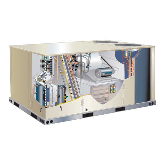
The KCC 7.5, 8.5, 10 and 12.5 ton (092, 102, 120, 150)
packaged cooling units are available in standard cooling
efficiency. Optional auxiliary electric heat is factory- or
field-installed in KCC units. Electric heat operates in sin-
gle or multiple stages depending on the kW input size.
7.5kW through 60kW heat sections are available for the
KCC packaged cooling units.
Standard and high efficiency units come standard with a
lightweight, all-aluminum condenser coil; optional, fin/tube
condenser coils are available. Hot gas by-pass (reheat) is
now an option for standard efficiency KCC units with fin
tube coils.
All KCC units are designed to accept any of several differ-
ent energy management thermostat control systems with
minimum field wiring. Factory- or field-provided control op-
tions connect to the unit with jack plugs. When "plugged
in" the controls become an integral part of the unit wiring.
Information contained in this manual is intended for use
by qualified service technicians only. All specifications are
subject to change. Procedures outlined in this manual are
presented as a recommendation only and do not super-
sede or replace local or state codes.
If the unit must be lifted for service, rig unit by attaching
four cables to the holes located in the unit base rail (two
holes at each corner). Refer to the installation instructions
for the proper rigging technique.
WARNING
To prevent serious injury or death:
1- Lock-out/tag-out before performing maintenance.
2- If system power is required (e.g., smoke detector
maintenance), disable power to blower, remove
fan belt where applicable, and ensure all
controllers and thermostats are set to the "OFF"
position before performing maintenance.
3- Always keep hands, hair, clothing, jewelry, tools,
etc., away from moving parts.
WARNING
Improper
installation,
service or maintenance can cause property damage,
personal injury or loss of life. Installation and service
must be performed by a licensed professional HVAC
installer or equivalent, service agency, or the gas
supplier
UNIT INFORMATION
UNIT INFORMATION
KCC092 through 150
adjustment,
alteration,
100098
As with any mechanical equipment, contact with
sharp sheet metal edges can result in personal
injury. Take care while handling this equipment and
wear gloves and protective clothing.
Electric shock hazard. Can cause injury
or death. Before attempting to perform
any service or maintenance, turn the
electrical power to unit OFF at disconnect
switch(es). Unit may have multiple power
supplies.
Options . . . . . . . . . . . . . . . . . . . . . .Page 2
Specifications . . . . . . . . . . . . . . . . . .Page 5
Blower Data . . . . . . . . . . . . . . . . . . Page 6
Electrical Data / Electric Heat Data . Page 10
Outdoor Sound Data. . . . . . . . . . . . . Page 14
I Unit Components . . . . . . . . . . . . . Page 16
II Placement and Installation . . . . . Page 27
III Start Up Operation . . . . . . . . . . . Page 27
IV Charging . . . . . . . . . . . . . . . . . . . Page 28
V System Service Checks . . . . . . . Page 34
VI Maintenance . . . . . . . . . . . . . . . . Page 34
VII Accessories . . . . . . . . . . . . . . . . Page 35
VIII Diagrams . . . . . . . . . . . . . . . . . . Page 43
Page 1
KCC SERIES
7.5 to 12.5 ton
CAUTION
WARNING
Table of Contents
Advertisement
Table of Contents

Subscribe to Our Youtube Channel
Related Manuals for Lennox KCC Series


Summary of Contents for Lennox KCC Series
-
Page 1: Table Of Contents
UNIT INFORMATION UNIT INFORMATION KCC SERIES 7.5 to 12.5 ton 100098 S e r v i c e L i t e r a t u r e KCC092 through 150 The KCC 7.5, 8.5, 10 and 12.5 ton (092, 102, 120, 150) packaged cooling units are available in standard cooling efficiency. -
Page 2: Options
OPT IONS / AC C ESSORIES Unit Model No Catalog Item Description Number 092 102 120 150 COOLING SYSTEM Condensate Drain Trap 22H54 Copper 76W27 Conventional Fin/Tube Condenser Coil Factory (Replaces Environ™ Coil System) (Required for Humiditrol Dehumidification option) ® Drain Pan Overflow Switch 74W42 Low Ambient Kits (0°F) - Page 3 OPT IONS / AC C ESSORIES Unit Model No Catalog Item Description Number 092 102 120 150 INDOOR AIR QUALITY Air Filters Healthy Climate High Efficiency Air Filters MERV 8 50W61 ® 20 x 25 x 2 (Order 4 per unit) 52W41 MERV 13 MERV 16...
- Page 4 OPT IONS / AC C ESSORIES Unit Model No Catalog Item Description Number 092 102 120 150 ECONOMIZER Standard Economizer (Not for Title 24) Standard Economizer with Single Temperature Control 13U45 Downflow or Horizontal Applications - Includes Barometric Relief Dampers and Air Hoods Standard Economizer Controls (Not for Title 24) Single Enthalpy Control 21Z09...
-
Page 5: Specifications
SP ECIFICATIO NS General Data Nominal Tonnage 7.5 Ton 8.5 Ton 10 Ton 12.5 Ton Model Number KCC092S4M KCC102S4M KCC120S4M KCC150S4M Efficiency Type Standard Standard Standard Standard Blower Type MSAV MSAV MSAV MSAV ® ® ® ® Multi-Stage Multi-Stage Multi-Stage Multi-Stage Air Volume Air Volume... -
Page 6: Blower Data
BLOWER DATA BELT D R IVE - 7 .5 | 8 .5 TO N KCC092S4M AND KCC102S4M - BASE UNIT BLOWER TABLE INCLUDES RESISTANCE FOR BASE UNIT ONLY (NO HEAT SECTION) WITH DRY INDOOR COIL AND AIR FILTERS IN PLACE. FOR ALL UNITS ADD: 1 −... - Page 7 BLOWER D ATA B ELT D R IVE - 1 0 | 1 2 .5 TO N KCC120S4M AND KCC150S4M - BASE UNIT BLOWER TABLE INCLUDES RESISTANCE FOR BASE UNIT ONLY (NO HEAT SECTION) WITH DRY INDOOR COIL AND AIR FILTERS IN PLACE.
- Page 8 BLO WER DATA FACTORY INSTALLED BELT DRIVE KIT SPECIFICATIONS Nominal Maximum Drive Kit Number RPM Range 590 - 890 800 - 1105 795 - 1195 3.45 730 - 970 3.45 940 - 1200 3.45 1015 - 1300 5.75 900 - 1135 5.75 1040 - 1315 5.75...
- Page 9 BLO WER DATA CEILING DIFFUSERS AIR RESISTANCE - in. w.g. RTD11 Step-Down Diffuser FD11 Flush Air Volume 1 Side, 2 Ends All Ends & Sides Diffuser Unit Size 2 Ends Open Open Open 2400 0.21 0.18 0.15 0.14 2600 0.24 0.21 0.18 0.17...
- Page 10 ELECTRIC AL/ELECTRIC H EAT DATA 7 .5 TO N Model No. KCC092S4 Voltage - 60Hz 208/230V - 3 Ph 460V - 3 Ph 575V - 3 Ph Compressor 1 Rated Load Amps (Non-Inverter) Locked Rotor Amps Compressor 2 Rated Load Amps (Non-Inverter) Locked Rotor Amps 36.5...
- Page 11 ELECTRIC AL/ELECTRIC H EAT DATA 8 .5 TO N Model No. KCC102S4 Voltage - 60Hz 208/230V - 3 Ph 460V - 3 Ph 575V - 3 Ph Compressor 1 Rated Load Amps (Non-Inverter) Locked Rotor Amps Compressor 2 Rated Load Amps 13.1 (Non-Inverter) Locked Rotor Amps...
- Page 12 ELECTRIC AL/ELECTRIC H EAT DATA 10 TO N Model No. KCC120S4 Voltage - 60Hz 208/230V - 3 Ph 460V - 3 Ph 575V - 3 Ph Compressor 1 Rated Load Amps (Non-Inverter) Locked Rotor Amps Compressor 2 Rated Load Amps (Non-Inverter) Locked Rotor Amps 38.9...
- Page 13 ELECT RICAL/ELECTR IC H EAT D ATA 12.5 TO N Model No. KCC150S4 Voltage - 60Hz 208/230V - 3 Ph 460V - 3 Ph 575V - 3 Ph Compressor 1 Rated Load Amps 17.6 (Non-Inverter) Locked Rotor Amps 66.1 55.3 Compressor 2 Rated Load Amps 22.4...
-
Page 14: Outdoor Sound Data
ELECT RIC HEAT C A PACITIES 7.5 kW 15 kW 22.5 kW 30 kW 45 kW 60 kW Volts Btuh No. of Btuh No. of Btuh No. of Btuh No. of Btuh No. of Btuh No. of Input Input Output Stages Input Output... - Page 15 KCC Parts Arrangement REHEAT EVAPORATOR BLOWER FILTERS COIL BLOWER CONDENSER COIL MOTOR (FOUR - 20 X 25 X 2”) FANS ECONOMIZER CONDENSER (OPTIONAL, BEHIND COIL PANEL) ELECTRIC HEAT (OPTIONAL) INVERTER CONDENSATE COMPRESSORS DRAIN FIGURE 1 KCC Control Box Y, G, J Volt Units TB13 K265 K125...
-
Page 16: I Unit Components
I-UNIT COMPONENTS 3-Terminal Strip TB1 All indoor thermostat connections are made at terminal All 7.5 through 12.5 ton (7.5 through 44 kW) units are con- block TB1 located in the control area. For thermostats figure to order units (CTO). The KCC unit components are without “occupied “... - Page 17 Plumbing and Refrigerant Circuit Detail Outdoor Coil Stage 1 (092 / 102) Outdoor Coil Stage 2 (120/150) Driers Outdoor Coil Stage 1 (120/150 Suction Line Outdoor Coil Discharge Line Stage 2 (092 / 102 Discharge Line Compressor 2 Compressor 1 COMPRESSOR 2 COMPRESSOR 1 S8 THERMAL...
- Page 18 KCC WITH OPTIONAL REHEAT KCC092 - 150 Shown Evaporator Coil Reversing Valve Reheat Coil (bottom) FIGURE 6 B-Cooling Components KCC150 Evaporators use a thermostatic expansion valve as primary refrigerant metering device. KCC092/102/120 All units use independent cooling circuits consisting of use thermostatic expansion valve on stage one and separate compressors, condenser coils and evaporator orifices on stage 2.
- Page 19 1-Compressors B1 and B2 To prevent coil icing, freezestats open during compressor operation to temporarily disable the respective compressor All units use two scroll compressors. Compressor capacity until the coil temperature rises. may vary from stage to stage. In all cases, the capacity of each compressor is added to reach the total capacity If the freezestats are tripping frequently due to coil icing, of the unit.
- Page 20 C-Blower Compartment 2 - Suction pressure must drop, discharge pressure must rise, and blower rotation must match rotation NOTE - Units equipped a Variable Frequency Drive (VFD) marking. are designed to operate on balanced, three-phase power. 3 - Disconnect all remote electrical power supplies. Operating units on unbalanced three-phase power will re- 4 - Reverse any two field-installed wires connected to duce the reliability of all electrical components in the unit.
- Page 21 STANDARD BLOWER ASSEMBLY SIDE VIEW TO INCREASE BELT TENSION 1- Loosen four bolts securing motor mounting base to frame. 2- Turn adjusting bolt to the right, or clockwise, to MOTOR ALLEN move the motor away from the blower housing. SCREW IMPORTANT - Gap between end of frame and motor PULLEY allel along gap.
- Page 22 LOCATION OF STATIC PRESSURE READINGS INSTALLATIONS WITH DUCTWORK INSTALLATIONS WITH CEILING DIFFUSERS ROOFTOP UNIT ROOFTOP UNIT RETURN AIR READING LOCATION RETURN AIR READING LOCATION SUPPLY SUPPLY TURN TURN FIRST BRANCH OFF OF MAIN RUN MAIN DUCT RUN SUPPLY AIR SUPPLY AIR READING READING DIFFUSER...
- Page 23 TABLE 2 MANUFACTURER’S NUMBERS DRIVE COMPONENTS ADJUSTABLE SHEAVE FIXED SHEAVE BELT DRIVE NO. BROWNING OEM PART BROWNING OEM PART BROWNING OEM PART 1VP34x7/8 31K6901 AK61x1 100244-20 AX54 100245-25 1VP40x7/8 79J0301 AK59x1 31K6801 AX55 100245-26 1VP34x7/8 31K6901 AK46x1 100244-17 AX52 100245-33 1VP44x7/8 53J9601 AK74x1...
- Page 24 130F + 6F (54.4C + 3.3C) on a temperature fall. For EHA100 units, the electric heat All KCC series units with electric heat use an electric section thermostat is factory set to open at 160F + 5F heat relay K9.
- Page 25 TABLE 3 KCC ELECTRIC HEAT SECTION FUSE RATING FUSE (3 each) EHA QUANTITY VOLTAGES & SIZE F3 - 1 F3 - 2 F3 - 3 F3 - 4 208/230V 25 Amp 250V ----- ----- ----- 460V 15 Amp 600V ----- ----- ----- EHA100-7.5...
- Page 26 EHA 7.5, 15, 22.5, 30, 45, 60KW ELECTRIC HEAT SECTION PARTS ARRANGEMENT HEATING ELEMENTS SECONDARY HE1 - HE6 LIMIT S20 SECONDARY SECONDARY LIMIT S20 LIMIT S20 ELECTRIC HEAT VESTIBULE SECONDARY LIMIT S20 SECONDARY LIMIT S20 SECONDARY LIMIT S20 ELECTRIC HEAT THERMOSTAT PRIMARY ELECTRIC HEAT LIMIT CONTROL WIRE...
-
Page 27: Placement And Installation
II-PLACEMENT AND INSTALLATION TABLE 4 Make sure the unit is installed in accordance with the COOLING OPERATION - NO ECONOMIZER installation instructions and all applicable codes. See T’Stat Compressors accessories section for conditions requiring use of the Fans optional roof mounting frame. Compr. -
Page 28: Charging
IV-CHARGING REFRIGERANT STAGES - 092, 102, 120, 150 A-All Aluminum Outdoor Coil WARNING CONDENSER COIL KG/KC 092, 102 - Stage 1 KG/KC 120, 150 - Stage 2 Refrigerant can be harmful if it is inhaled. Refrigerant must be used and recovered responsibly. (BOTH FANS ARE ENERGIZED CONDENSER COIL Failure to follow this warning may result in personal... - Page 29 TABLE 6 581125-01 KG/KC 092S Normal Operating Pressures - All-Aluminum Coil Outdoor Coil Entering Air Temperature 65°F 75°F 85°F 95°F 105°F 115°F Suct Disc Suct Disc Suct Disc Suct Disc Suct Disc Suct Disc (psig) (psig) (psig) (psig) (psig) (psig) (psig) (psig) (psig)
- Page 30 TABLE 7 581126-01 KG/KC 102S Normal Operating Pressures - All-Aluminum Coil Outdoor Coil Entering Air Temperature 65°F 75°F 85°F 95°F 105°F 115°F Suct Disc Suct Disc Suct Disc Suct Disc Suct Disc Suct Disc (psig) (psig) (psig) (psig) (psig) (psig) (psig) (psig) (psig)
- Page 31 TABLE 8 581127-01 KG/KC 120S Normal Operating Pressures - All-Aluminum Coil Outdoor Coil Entering Air Temperature 65°F 75°F 85°F 95°F 105°F 115°F Suct Disc Suct Disc Suct Disc Suct Disc Suct Disc Suct Disc (psig) (psig) (psig) (psig) (psig) (psig) (psig) (psig) (psig)
- Page 32 TABLE 9 581128-01 KG/KC 150S Normal Operating Pressures - All-Aluminum Coil Outdoor Coil Entering Air Temperature 65°F 75°F 85°F 95°F 105°F 115°F Suct Disc Suct Disc Suct Disc Suct Disc Suct Disc Suct Disc (psig) (psig) (psig) (psig) (psig) (psig) (psig) (psig) (psig)
- Page 33 B-Refrigerant Charge and Check - Fin/Tube Coil TABLE 11 581130-01 WARNING - Do not exceed nameplate charge under KGC/KCC102S Fin/Tube - W & W/O Reheat any condition. Outdoor CIRCUIT 1 CIRCUIT 2 This unit is factory charged and should require no further Coil Discharge Suction...
-
Page 34: System Service Checks
TABLE 14 REMOVE FILTERS APPROACH TEMPERATURE - Fin/Tube - TXV Liquid Temp. Minus Ambient Temp. Unit 1st Stage 2nd Stage 092S 7°F + 1 (3.9°C + 0.5) 9°F + 1 (5.0°C + 0.5) 102S 5°F + 1 (2.8°C + 0.5) 15°F + 1 (8.3°C + 0.5) 120S 3°F + 1 (1.6°C + 0.5) -
Page 35: Accessories
VII-OPTIONAL ACCESSORIES TYPICAL FLASHING DETAIL The accessories section describes the application of most UNIT BASE of the optional accessories which can be installed to the BOTTOM KCC units. UNIT BASE RAIL A-Drain Pan Overflow Switch S149 (optional) The overflow switch is used to interrupt cooling operation when excessive condensate collects in the drain pan. - Page 36 F-K1ECON20B / K1ECON22B-1 Economizer, TABLE 15 (Field- or Factory-Installed) Sensors Dampers will modulate to 55°F dis- charge air (RT6) when: See specific economizer installation instructions for more detail for both K1ECON20B and high performance Single OA Sensible OA temperature (S175) is lower than free cooling setpoint.
- Page 37 C1DAMP20B-1 MOTORIZED OUTDOOR AIR DAMPER MOTORIZED DAMPER COVER PANEL HORIZONTAL SUPPLY AIR OPENING COMPRESSOR HORIZONTAL SECTION RETURN AIR OPENING LOWER PANEL C1DAMP10B-2 MANUAL OUTDOOR AIR DAMPER COVER PANEL MANUAL DAMPER HORIZONTAL SUPPLY AIR OPENING COMPRESSOR HORIZONTAL SECTION RETURN AIR OPENING LOWER PANEL FIGURE 21 Page 37...
- Page 38 TABLE 16 A6 ENTHALPY CONTROLLER ENTHALPY FREE COOLING SETPOINTS Control Setting Enthalpy Setpoint At 50% RH 73° F (23° C) MUM POSITION 70° F (21° C) 67° F (19° C) 63° F (17° C) IAQ MAXIMUM POSITION Open *Setting A is recommended (set higher than Damper Minimum Position minimum position)
- Page 39 CHART 1 CALCULATE MINIMUM FRESH AIR PERCENTAGE MIXED AND RETURN AIR TEMPERATURE OUTDOOR AIR TEMPERATURE FIGURE 23 DCV Set and Max Settings During the occupied time period dampers will open to DCV MAX when IAQ reading is above setpoint (regardless of Adjust settings when an optional IAQ sensor is thermostat demand or outdoor air suitability).
- Page 40 TABLE 17 ECONOMIZER OPERATION-OUTDOOR AIR IS SUITABLE FOR FREE COOLING -- FREE COOL LED “ON” Damper Position Thermostat Demand Mechanical Cooling Unoccupied Occupied Closed Closed Closed Minimum Modulating Modulating Modulating Modulating Stage 1 Modulating Modulating Stage 2 TABLE 18 ECONOMIZER OPERATION-OUTDOOR AIR IS NOT SUITABLE FOR FREE COOLING -- FREE COOL LED “OFF” Damper Position Thermostat Demand Mechanical Cooling...
- Page 41 I-Power Exhaust Fan A6 ENTHALPY CONTROLLER The power exhaust fan (PEF) requires the use of a gravity exhaust damper and economizer and is used in downflow ADJUST POWER applications only. See FIGURE 27. The PEF provides EXHAUST FAN exhaust air pressure relief and also runs when return air SETPOINT dampers are closed and the supply air blower is operating.
- Page 42 M-Hot Gas Reheat Start-Up and Operation 1 - Make sure reheat is wired as shown in wiring section. General 2 - Initiate a dehumidification demand by adjusting Hot gas reheat units provide a dehumidifying mode of dehumidistat setpoint knob BELOW indoor operation.
- Page 43 VIII-Wiring Diagrams and Sequence of Operation Page 43...
- Page 44 Sequence of Operation Power: 1st Stage Cooling (compressor B1) 1 - Line voltage from unit disconnect energizes 5 - First stage cooling demand Y1 and G are energized transformer T1. T1 provides 24VAC power to by the thermostat. G energizes blower. 24VAC is terminal strip TB1.
- Page 45 EHA-7.5, 15, 22.5, 30, 45 & 60kW Y VOLTAGE KCC SERIES UNITS FUSE−ELECTRIC HEAT 2 FUSE−ELECTRIC HEAT 3 FUSE−ELECTRIC HEAT 4 K9−1 ELEMENT−ELECT HEAT 3 ELEMENT−ELECT HEAT 4 ELEMENT−ELECT HEAT 5 ELEMENT−ELECT HEAT 6 K9−2 THERMOSTAT−ELECTRIC HEAT LIMIT S157 SWITCH−LIMIT,SECONDARY ELECT HT 2 S158 SWITCH−LIMIT,SECONDARY ELECT HT 3...
- Page 46 EHA-7.5, 15, 22.5, 30, 45 & 60kW G, J VOLTAGE KCC SERIES UNITS COMPONENT DELAY-ELECTRIC HEAT FUSE-ELECTRIC HEAT FUSE-UNIT FUSE-ELECTRIC HEAT 2 ELEMENT-ELECTRIC HEAT 1 K9−1 ELEMENT-ELECTRIC HEAT 2 ELEMENT-ELECTRIC HEAT 3 ELEMENT-ELECTRIC HEAT 4 JACK-ELECT HT SUB-BUS KIT K9,-1,2...
- Page 47 Sequence of Operation -EHA 7.5, 15, 22.5, 30, 45, 60 kW - Y, G and J HEATING ELEMENTS: 4 - If S20 and S157 (S158 on Y-volt units) secondary electric heat limits remain closed, HE1 and HE2 1 - Terminal Strip TB3 is energized when the unit (HE3 and HE4 on Y-volt units) electric heat is disconnect closes.
- Page 48 ELECTRONIC OR ELECTROMECHANICAL THERMOSTAT Page 48...
- Page 49 ELECTRONIC OR ELECTROMECHANICAL THERMOSTAT Page 49...
- Page 50 ELECTRONIC OR ELECTROMECHANICAL THERMOSTAT A183 USED ON UNITS WITH VFD ONLY Page 50...
- Page 51 ECONOMIZER (POL224) AUX2- AUX2- AUX1- AUX1- RT26 AUX- RT27 S-COM S-24V 0-10 24VAC ACT- BLACK COMMON 2-10 GRAY ACT2-10 ACT- PINK ACT-FB ACT- COMPONENT CONTROL - ECONOMIZER SENSOR - OUTDOOR ENTHALPY OUTDOOR AIR TEMP SENSOR RT26 OR OUTDOOR AIR SENSOR - INDOOR ENTHALPY ENTHALPY SENSOR A7 MAY BE USED.
Need help?
Do you have a question about the KCC Series and is the answer not in the manual?
Questions and answers
what are the exterior dimensions for KCC120S & for KCC150S