Table of Contents
Advertisement
CONTENTS
SAFETY CONSIDERATIONS . . . . . . . . . . . . . . . . . . . 1
PRE-INSTALLATION . . . . . . . . . . . . . . . . . . . . . . . . . . 2
General . . . . . . . . . . . . . . . . . . . . . . . . . . . . . . . . . . . . . 2
Unit Identification . . . . . . . . . . . . . . . . . . . . . . . . . . . . 2
Warranty . . . . . . . . . . . . . . . . . . . . . . . . . . . . . . . . . . . . 3
VAV CCN Controls and OPEN VAV Controls . . . . . . 4
VVT CCN Controls and OPEN VVT Controls . . . . . . 4
Analog Electronic Controls . . . . . . . . . . . . . . . . . . . . 4
Pneumatic Controls . . . . . . . . . . . . . . . . . . . . . . . . . . 4
Direct Digital Controls (By Others) . . . . . . . . . . . . . . 4
No Control Units . . . . . . . . . . . . . . . . . . . . . . . . . . . . . 4
INSTALLATION . . . . . . . . . . . . . . . . . . . . . . . . . . . . . . 4
Step 1 - Install Fan-Powered Box . . . . . . . . . . . . . . 4
Step 2 - Make Duct Connections . . . . . . . . . . . . . . . 5
Step 3 - Connect Power Wiring . . . . . . . . . . . . . . . . 5
Step 4 - Set Up System and Calibrate . . . . . . . . . . . 7
START-UP . . . . . . . . . . . . . . . . . . . . . . . . . . . . . . . . . . 8
General . . . . . . . . . . . . . . . . . . . . . . . . . . . . . . . . . . . . . 8
Initial Start-Up Procedures . . . . . . . . . . . . . . . . . . . . . 8
Balancing Carrier Fan Terminals . . . . . . . . . . . . . . . . 9
Speed Controller . . . . . . . . . . . . . . . . . . . . . . . . . . . . 16
Setting Fan Air Flow with ECM Motors . . . . . . . . . . 17
Control Sequences (1300-1305, 1400-1401) . . . . 33
Manufacturer reserves the right to discontinue, or change at any time, specifications or designs without notice and without incurring obligations.
Catalog No. 04-53450004-01
Installation, Start-Up and
Service Instructions
Printed in U.S.A.
Form 45-6SI
Variable Air Volume Terminals
Units with Single-Function Controllers . . . . . . . . . .33
Page
1306-1317 and 1402-1405) . . . . . . . . . . . . . . . . . . .34
Operation Sequences . . . . . . . . . . . . . . . . . . . . . . . .34
Procedures . . . . . . . . . . . . . . . . . . . . . . . . . . . . . . .35
Thermostat Installation . . . . . . . . . . . . . . . . . . . . . . .35
Programming Thermostat . . . . . . . . . . . . . . . . . . . . .36
Controls . . . . . . . . . . . . . . . . . . . . . . . . . . . . . . . . . . .37
Fan Motor and Wheel . . . . . . . . . . . . . . . . . . . . . . . . .37
Fan Motor Wiring . . . . . . . . . . . . . . . . . . . . . . . . . . . .37
Fan Motor Maintenance . . . . . . . . . . . . . . . . . . . . . . .37
SAFETY CONSIDERATIONS
IMPORTANT: Air-handling equipment will provide safe
and reliable service when operated within design specifica-
tions. The equipment should be operated and serviced only
by authorized personnel who have a thorough knowledge of
system operation, safety devices, and emergency proce-
dures. Good judgment should be used in applying any man-
ufacturer's instructions to avoid injury to personnel or
damage to equipment and property.
Disconnect all power to the unit before performing mainte-
nance or service. Unit may automatically start if power is not
disconnected. Electrical shock and personal injury could result.
If it is necessary to remove and dispose of mercury contactors
in electric heat section, follow all local, state, and federal
laws regarding disposal of equipment containing hazardous
materials.
See Fig. 1 for the Proposition 65 warning label.
!
WARNING: Cancer - www.P65Warnings.ca.gov
Fig. 1 - Proposition 65 Warning Label
Pg 1
45J,K,M,N,Q,R
Fan Powered
WARNING
WARNING
12-22
Replaces: 45-5SI
Advertisement
Table of Contents

Related Manuals for Carrier 45 Series


Summary of Contents for Carrier 45 Series
-
Page 1: Table Of Contents
Initial Start-Up Procedures ..... 8 in electric heat section, follow all local, state, and federal Balancing Carrier Fan Terminals ....9 laws regarding disposal of equipment containing hazardous •... -
Page 2: Pre-Installation
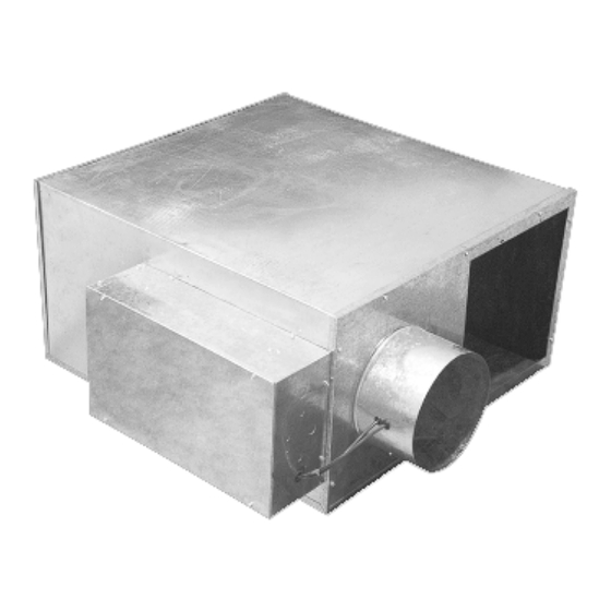
Read all labels on a typical unit before attempting installation. Control boxes are as- sembled as indicated on the identification label. Contact your local Carrier representative for more information. Fig. 2 — Parallel Flow Unit (45M Shown) FAN UNIT 10 579600 5 —... -
Page 3: Installation Precaution
See Installation section on page 4 for unit suspension details. operation. Warranty SERVICE ACCESS All Carrier-furnished items carry the standard Carrier warranty. Provide service clearance for unit access (see Installation section on page 4 for details). Table 1 — 45J Unit Weights... -
Page 4: Control Options
These controls may be used in fan speed control, 24-v transformer, and fan relay. a stand-alone terminal, or as part of the Carrier DDC control sys- tem. All control arrangements include a standard inlet flow sensor,... -
Page 5: Position Unit
All units are wired for level. a single point electrical connection to the fan and electric heater (if equipped). Electric heaters provided by Carrier INSTALL UNIT are balanced by kW per stage. The installing electrician... - Page 6 FIELD-SUPPLIED HANGER OPTIONAL BRACKET ACCESSORY HANGER FIELD-SUPPLIED HANGING STRAPS DO NOT suspend unit by trapeze hangers that interfere with the unit access panel. Fig. 6 — Typical Unit Suspension Methods (45K Shown) Fig. 7 — Typical Perimeter Installation — Constant Volume Fan-Powered Box...
-
Page 7: Step 4 - Set Up System And Calibrate
Carrier inlet areas are shown in Table 8, which illustrates the de- required for balancing. Refer to the submittal information for these sign air volume. -
Page 8: Start-Up
If the fan box is installed with elec- tric heat, the electric heat voltage may exceed the blower NOTE: All 45 Series terminal units are shipped with cardboard motor voltage requirement. Excessive voltage to the fan packaging rings placed in one side of the blower housing internal box may seriously damage it. -
Page 9: Balancing Carrier Fan Terminals
Balancing Carrier Fan Terminals quantity of cold primary air entering the terminal and the condi- Carrier fan terminal units contain primary air dampers which, un- tioned space. If required airflow levels are specified with the job der the control of a volume controller, regulate the amount of cold order, the minimum and maximum cfm levels will be set at the air distributed to the space. - Page 10 START-UP CHECKLIST JOB NAME _________________________________________ JOB LOCATION _____________________________________ CUSTOMER ________________________________________ ENGINEER _________________________________________ BUILDING LOCATION/FLOOR _________________________ BUS NUMBER ______________________________________ CONTROL SET POINTS Cooling Heating Calibration Heat Occupied Unoccupied Zone (cfm) (cfm) Gain Size Number Address # (in./cfm) Type Mult. Fig. 10 — Air Terminal Performance Sheet...
- Page 11 Table 9 — 45J Series Fan Powered Terminal Unit Performance a,b,c 45J WITH PSC FAN MOTOR FAN AIRFLOW (cfm) PRIMARY AIRFLOW (cfm) MOTOR AMPS UNIT SIZE INLET SIZE (in.) MOTOR HP 120V 208/240V 277V 52 or 0 1/10 52 or 0 92 or 0 92 or 0 1440...
- Page 12 Table 10 — 45K Series Fan Powered Terminal Unit Performance a,b,c 45K WITH PSC FAN MOTOR FAN AIRFLOW PRIMARY AIRFLOW MOTOR AMPS MOTOR (cfm) (cfm) UNIT SIZE INLET SIZE (in.) 120V 208/240V 277V 52 or 0 1/10 92 or 0 52 or 0 92 or 0 1100...
- Page 13 Table 11 — 45Q Series Fan Powered Terminal a,b,c 45Q UNITS WITH PSC FAN MOTOR INLET FAN AIRFLOW PRIMARY AIRFLOW MOTOR AMPS UNIT SIZE MOTOR HP SIZE 120V 208/240V 277V (in.) 92 or 0 1075 143 or 0 1075 143 or 0 1432 1650 (2) 1/6...
-
Page 14: Balancing 45M,N,R Parallel Flow Units
BALANCING 45M,N,R PARALLEL FLOW UNITS entering the terminal and the conditioned space. If required air- flow levels are specified with the job order, the minimum and A parallel fan terminal is designed to operate with the fan supply- maximum cfm levels will be set at the factory. If minimum and ing air equal to 40 to 60% of the VAV damper maximum setting. - Page 15 Table 12 — 45M Parallel Fan Powered Terminal Unit Performance a,b,c 45M WITH PSC FAN MOTOR FAN AIRFLOW (cfm) PRIMARY AIRFLOW (cfm) MOTOR AMPS UNIT SIZE INLET SIZE (in.) MOTOR HP 120V 208/240V 277V 52 or 0 1/10 92 or 0 52 or 0 92 or 0 92 or 0...
-
Page 16: Speed Controller
45R maximum/minimum fan airflow is based on 0.25 in. wg external (downstream) static pressure, respectively. Speed Controller Each Carrier fan powered air terminal unit is equipped with a fan SCR speed controller, located on the bottom of the control box. -
Page 17: Setting Fan Air Flow With Ecm Motors
Setting Fan Air Flow with ECM Motors Several terminal unit models are available with ECM motors for easy balancing. These motors supply a determined amount of air regardless of static pressure from ductwork layout or air distribu- tion. The ECM motors are programmed to provide a maximum cfm depending on model and unit size. - Page 18 Table 15 — 45K Size 3 — ECM Calibration (cont) Table 15 — 45K Size 3 — ECM Calibration ACU-P ACU-P ACU-0 ACU-0 REMOTE REMOTE REMOTE 0-10VDC REMOTE 0-10VDC 2-10VDC 2-10VDC (0-20mA) (0-20mA) (4-20mA) (4-20mA) DC SIGNAL DC SIGNAL DC SIGNAL DC SIGNAL MANUAL % (OPTION 7)
- Page 19 Table 16 — 45K Size 6 — ECM Calibration (cont) Table 16 — 45K Size 6 — ECM Calibration ACU-P ACU-P ACU-0 ACU-0 REMOTE REMOTE REMOTE 0-10VDC REMOTE 0-10VDC 2-10VDC 2-10VDC (0-20mA) (0-20mA) (4-20mA) (4-20mA) DC SIGNAL DC SIGNAL DC SIGNAL DC SIGNAL MANUAL % (OPTION 7)
- Page 20 Table 17 — 45K Size 7 ECM Calibration (cont) Table 17 — 45K Size 7 ECM Calibration ACU-P ACU-P ACU-0 ACU-0 REMOTE REMOTE REMOTE 0-10VDC REMOTE 0-10VDC 2-10VDC 2-10VDC (0-20mA) (0-20mA) (4-20mA) (4-20mA) DC SIGNAL DC SIGNAL DC SIGNAL DC SIGNAL MANUAL % (OPTION 7) MANUAL %...
- Page 21 Table 18 — 45N Size 4 ECM Calibration (cont) Table 18 — 45N Size 4 ECM Calibration ACU-P ACU-P ACU-0 ACU-0 REMOTE REMOTE REMOTE 0-10VDC REMOTE 0-10VDC 2-10VDC 2-10VDC (0-20mA) (0-20mA) (4-20mA) (4-20mA) DC SIGNAL DC SIGNAL DC SIGNAL DC SIGNAL MANUAL % (OPTION 7) MANUAL %...
- Page 22 Table 19 — 45N Size 7 ECM Calibration (cont) Table 19 — 45N Size 7 ECM Calibration ACU-P ACU-P ACU-0 ACU-0 REMOTE REMOTE REMOTE 0-10VDC REMOTE 0-10VDC 2-10VDC 2-10VDC (0-20mA) (0-20mA) (4-20mA) (4-20mA) DC SIGNAL DC SIGNAL DC SIGNAL DC SIGNAL MANUAL % (OPTION 7) MANUAL %...
- Page 23 Table 20 — 45J Size 3 ECM Calibration (cont) Table 20 — 45J Size 3 ECM Calibration ACU-P ACU-P ACU-0 ACU-0 REMOTE REMOTE REMOTE 0-10VDC REMOTE 0-10VDC 2-10VDC 2-10VDC (0-20mA) (0-20mA) (4-20mA) (4-20mA) DC SIGNAL DC SIGNAL DC SIGNAL DC SIGNAL MANUAL % (OPTION 7) MANUAL %...
- Page 24 Table 21 — 45J Size 6 ECM Calibration (cont) Table 21 — 45J Size 6 ECM Calibration ACU-P ACU-P ACU-0 ACU-0 REMOTE REMOTE REMOTE 0-10VDC REMOTE 0-10VDC 2-10VDC 2-10VDC (0-20mA) (0-20mA) (4-20mA) (4-20mA) DC SIGNAL DC SIGNAL DC SIGNAL DC SIGNAL MANUAL % (OPTION 7) MANUAL %...
- Page 25 Table 22 — 45J Size 7 ECM Calibration (cont) Table 22 — 45J Size 7 ECM Calibration ACU-P ACU-P ACU-0 ACU-0 REMOTE REMOTE REMOTE 0-10VDC REMOTE 0-10VDC 2-10VDC 2-10VDC (0-20mA) (0-20mA) (4-20mA) (4-20mA) DC SIGNAL DC SIGNAL DC SIGNAL DC SIGNAL MANUAL % (OPTION 7) MANUAL %...
- Page 26 Table 23 — 45Q Size 3 ECM Calibration (cont) Table 23 — 45Q Size 3 ECM Calibration ACU-P ACU-P ACU-0 ACU-0 REMOTE REMOTE REMOTE 0-10VDC REMOTE 0-10VDC 2-10VDC 2-10VDC (0-20mA) (0-20mA) (4-20mA) (4-20mA) DC SIGNAL DC SIGNAL DC SIGNAL DC SIGNAL MANUAL % (OPTION 7) MANUAL %...
- Page 27 Table 24 — 45Q Size 4 ECM Calibration (cont) Table 24 — 45Q Size 4 ECM Calibration ACU-P ACU-P ACU-0 ACU-0 REMOTE REMOTE REMOTE 0-10VDC REMOTE 0-10VDC 2-10VDC 2-10VDC (0-20mA) (0-20mA) (4-20mA) (4-20mA) DC SIGNAL DC SIGNAL DC SIGNAL DC SIGNAL MANUAL % (OPTION 7) MANUAL %...
- Page 28 Table 25 — 45Q Size 5 ECM Calibration (cont) Table 25 — 45Q Size 5 ECM Calibration ACU-P ACU-P ACU-0 ACU-0 REMOTE REMOTE REMOTE 0-10VDC REMOTE 0-10VDC 2-10VDC 2-10VDC (0-20mA) (0-20mA) (4-20mA) (4-20mA) DC SIGNAL DC SIGNAL DC SIGNAL DC SIGNAL MANUAL % (OPTION 7) MANUAL %...
- Page 29 Table 26 — 45Q DOAS Size 3 ECM Calibration (cont) Table 26 — 45Q DOAS Size 3 ECM Calibration ACU-P ACU-P ACU-0 ACU-0 REMOTE REMOTE REMOTE 0-10VDC REMOTE 0-10VDC 2-10VDC 2-10VDC (0-20mA) (0-20mA) (4-20mA) (4-20mA) DC SIGNAL DC SIGNAL DC SIGNAL DC SIGNAL MANUAL % (OPTION 7)
- Page 30 Table 27 — 45Q DOAS Size 5 ECM Calibration (cont) Table 27 — 45Q DOAS Size 5 ECM Calibration ACU-P ACU-P ACU-0 ACU-0 REMOTE REMOTE REMOTE 0-10VDC REMOTE 0-10VDC 2-10VDC 2-10VDC (0-20mA) (0-20mA) (4-20mA) (4-20mA) DC SIGNAL DC SIGNAL DC SIGNAL DC SIGNAL MANUAL % (OPTION 7)
- Page 31 Table 28 — 45R Size 2 ECM Calibration (cont) Table 28 — 45R Size 2 ECM Calibration ACU-P ACU-P ACU-0 ACU-0 REMOTE REMOTE REMOTE 0-10VDC REMOTE 0-10VDC 2-10VDC 2-10VDC (0-20mA) (0-20mA) (4-20mA) (4-20mA) DC SIGNAL DC SIGNAL DC SIGNAL DC SIGNAL MANUAL % (OPTION 7) MANUAL %...
- Page 32 Table 29 — 45R Size 4 ECM Calibration (cont) Table 29 — 45R Size 4 ECM Calibration ACU-P ACU-P ACU-0 ACU-0 REMOTE REMOTE REMOTE 0-10VDC REMOTE 0-10VDC 2-10VDC 2-10VDC (0-20mA) (0-20mA) (4-20mA) (4-20mA) DC SIGNAL DC SIGNAL DC SIGNAL DC SIGNAL MANUAL % (OPTION 7) MANUAL %...
-
Page 33: General - Single Function Pneumatic Controller Control Sequences (1300-1305, 1400-1401)
PNEUMATIC CONTROLS General — Single Function Pneumatic Control- ler Control Sequences (1300-1305, 1400-1401) To properly balance the system, all ductwork and outlets must be installed and connected tightly. Refer to piping/wiring diagram on unit for specifics for the control sequence selected for the unit. Units with Single-Function Controllers CS C- 20 04 0- 1”... -
Page 34: Units With Multi-Function Controllers (Sequences 1306-1317 And 1402-1405)
c. With the 15 psig (or greater) thermostat signal, measure 45M,N,R Units: the unit minimum airflow. DANC, DANO — Disconnect the thermostat line from the DANO blower control. a. At a 0 psi stat signal, measure the unit minimum airflow. RANC, RANO —... -
Page 35: Analog Controls Installation And Balancing
heating coils, if supplied, are full on. See Table 30 for NOTE(S): pneumatic control troubleshooting. The multi-function control system uses a KMC CSC 3000 Adjust the “HI STAT” knob, with a 15 psi thermostat sig- series velocity controller with a rated air consumption of 1.00 nal, to obtain the desired airflow setting. -
Page 36: Programming Thermostat
different menu options or set a specific value. Use the Set- Programming Thermostat point button to select a menu or set a value. The thermostat has three sequences that are selectable To set the minimum and maximum airflow limits, Use from the display screen. -
Page 37: Controls
SERVICE BROWN TO CAPACITOR WARNING LOCK OPEN AND TAG heater electrical disconnect before working on this equipment. Otherwise, one leg of the 3-leg BLACK #12 heater remains energized. WHITE #12 TO Controls TERMINAL BLOCK/ DISCONNECT SWITCH No periodic preventive maintenance is necessary. Fan Motor and Wheel BLACK #12 TO The fan motor and wheel are accessible from the bottom of the... - Page 38 If fan motor does not run: If fan motor runs, insufficient airflow: Make sure that there is free rotation of blower wheel. Check for ductwork restrictions, dirty air filters, and Remove fan packing. clogged water coils. Verify that there is no freight or installation damage. Re-adjust fan speed control.
- Page 40 © 2022 Carrier Manufacturer reserves the right to discontinue, or change at any time, specifications or designs without notice and without incurring obligations. Catalog No. 04-53450004-01 Printed in U.S.A. Form 45-6SI Pg 40 12-22 Replaces: 45-5SI...
Need help?
Do you have a question about the 45 Series and is the answer not in the manual?
Questions and answers