Carrier 52M Performance Series Installation And Operating Instructions Manual
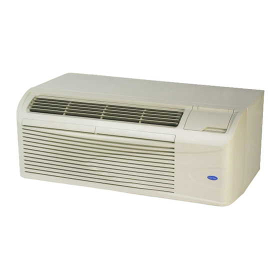
52m performance series packaged terminal air conditioner / heat pump 7,000 - 15,000 btuh
Hide thumbs
Also See for 52M Performance Series:
- Product data (42 pages) ,
- Owner's manual (27 pages) ,
- Wiring diagrams (4 pages)
Table of Contents
Advertisement
52M
Performancet
Packaged Terminal Air Conditioner / Heat Pump
7,000 --- 15,000 Btuh
Installation and Operating
Thank you for purchasing a Carrier PTAC. Please read this Owner's Information Manual carefully
before installing and using this appliance. Keep this manual for future reference.
For your convenience, please record the model and serial numbers of your new equipment in the
spaces provided. This information, along with the installation data and dealer contact information,
will be helpful should your system require maintenance or service.
UNIT INFORMATION
Model # ________________________________
Serial # ________________________________
INSTALLATION INFORMATION
Date Installed ___________________________
Series
Instructions
NOTE TO EQUIPMENT OWNER:
DEALERSHIP CONTACT INFORMATION
Company Name: __________________________________
Address: _________________________________________
_________________________________________________
Phone Number: ________________________________
Technician Name: _________________________________
_________________________________________________
A07228
Advertisement
Table of Contents

Subscribe to Our Youtube Channel
Related Manuals for Carrier 52M Performance Series


Summary of Contents for Carrier 52M Performance Series
-
Page 1: Installation And Operating
A07228 NOTE TO EQUIPMENT OWNER: Thank you for purchasing a Carrier PTAC. Please read this Owner’s Information Manual carefully before installing and using this appliance. Keep this manual for future reference. For your convenience, please record the model and serial numbers of your new equipment in the spaces provided. -
Page 2: Table Of Contents
............... Installation of Carrier Wall Sleeve Using Non- -Carrier Grille . -
Page 3: Safety Considerations
READ ALL INSTRUCTIONS BEFORE INSTALLATION OR USE SAFETY CONSIDERATIONS GENERAL Recognize safety information. This is the safety- -alert Thank you for choosing Carrier’s best PTAC ever! You can feel confident in your selection because the symbol . When you see this symbol on the unit and... - Page 4 • Premium Sound – Your Premium unit is also located in the lower right corner is the unit On/Off Carrier’s quietest PTAC ever. Not only does it have 2 status LED. If the unit is in ON mode, the LED will fan motors and a tangential blower wheel for be green.
-
Page 5: Unit Features
UNIT FEATURES CONTINUED • Unit Configuration – There are many different • Limit the Setpoint Range - - The unit can be configuration possibilities, through both dipswitches configured to limit the controlling setpoint range. The and the digital keypad, that allow you to configure display will always show the complete setpoint range, the unit for your exact application. -
Page 6: Electrical Data
ELECTRICAL DATA Table 1—SUGGESTED BRANCH CIRCUIT WIRE SIZES* WARNING NAMEPLATE AMPS AWG WIRE SIZE{ 7.0 to 12 ELECTRICAL SHOCK HAZARD 12.1 to 16 Failure to follow this warning could result in personal injury or death and/or property damage 16.1 to 24 DO NOT alter cord or plug or use an extension cord. -
Page 7: Installation
Trane, and Friedrich sleeves/grilles (be sure outdoor Table 3—Retrofit Wall Sleeves grille is installed on the sleeve). See Table 3 for Manufacturer Wall Sleeve Part Number details. Carrier Corporation must approve any other General Electric Metal Sleeve RAB71 retrofit application. Plastic Sleeve RAB77... -
Page 8: Retrofit Sleeve Preparation
-manufactured windows with built- -in grilles or renovations where a Carrier sleeve is used with an existing non- -Carrier grille. Use of a Carrier wall sleeve with a non- -Carrier grille requires installation of an Accessory Baffle Kit (see A07056 Fig. -
Page 9: Install Unit Into Wall Sleeve
INSTALL UNIT INTO WALL SLEEVE 1. Carefully remove shipping tape from the front panel and vent door. See Fig. 9 . 2. Remove shipping screw from the vent door, if present. See Fig. 10. 3. Remove front panel. See Fig. 11. 4. -
Page 10: How To Connect
HOW TO CONNECT IMPORTANT: Please read following electrical safety data carefully. Unit connector WARNING ELECTRICAL SHOCK AND/OR UNIT OPERATION AND DAMAGE HAZARD Failure to follow this warning could result in personal injury or death and/or unit operation and damage. Junction box cover Junction box Follow the National Electrical Code (NEC) or local codes and ordinances. -
Page 11: System Configuration
SYSTEM CONFIGURATION VENTILATION CONTROL The ventilation control lever is located at left side of unit, behind front panel. NOTE: The vent door shipping hardware must be Vent Control Open removed before using vent control lever. See (Pull lever through label to operate.) Installation Instructions. -
Page 12: Dipswitches
DIP SWITCHES Auxiliary dip switch controls are located behind front panel, through an opening below the control panel. To access, remove front panel. See Fig. 11. Dip switches are accessible without opening the control box. Unit must be powered OFF to Dip Switches effectively change their status. -
Page 13: Keypad Configuration
KEYPAD CONFIGURATION Keypad Configuration Indoor Temperature Display: Allows further configuration of system to desired Change between showing setpoint only on the display application. Changes do not take affect until power is during heating and cooling modes “SP” or displaying cycled on the unit. room temperature during heating and cooling modes “AA”. -
Page 14: Auxiliary Controls
AUXILIARY CONTROLS R W Y O Gh Gl C WALL THERMOSTAT TERMINAL NOTE: Carrier thermostats are recommended. IMPORTANT: Only trained, qualified personnel should access electrical panel on unit and install electrical accessories. Please contact your local electrical contractor, dealer, or distributor for assistance. -
Page 15: Wall Thermostat Terminal
INTELLIGENT SELF- - CHECKING CONTROL Your Carrier PTAC has a computer board that continuously checks key components of the unit to ensure they are operating properly. Under normal operation, unit status indicator (STATUS, on main PCB), light is steadily ON. -
Page 16: Operation
OPERATION IMPORTANT: When unit is first started, high humidity conditions can cause condensation to form on discharge grille. Keep doors and windows closed. Room humidity will decrease and moisture will evaporate. TEMP CONTROL FAN, MODE& OPERATION A07061 Fig. 27 – PTAC CONTROLS ABOUT THE CONTROLS ON YOUR UNIT NOTE: In case of a power failure, the unit will 2. -
Page 17: Care And Cleaning
CARE AND CLEANING FRONT PANEL AND CASE AIR FILTERS IMPORTANT: TURN UNIT OFF BEFORE Turn unit off and disconnect power supply. CLEANING To clean, use water and a mild detergent. DO NOT use bleach or abrasives. Some commercial cleaners CAUTION may damage the plastic parts. -
Page 18: Preventative Maintenance
PREVENTATIVE MAINTENANCE Preventative maintenance is essential to proper unit operation, efficiency and longevity. To ensure equipment operates properly, it must be properly maintained. Equipment operation should be checked and verified several times during each year. During regular unit inspection and maintenance, follow the guidelines below: Clean both sides of outdoor coil. -
Page 19: Troubleshooting
TROUBLESHOOTING POSSIBLE CAUSES SOLUTIONS UNIT DOES NOT START • Unit may have become unplugged • Check that plug is plugged securely in wall receptacle. • Fuse may have blown Note :Plug has a test/reset button on it. Make sure that the plug •... - Page 20 NOTES...
- Page 21 NOTES...
- Page 22 NOTES...
-
Page 24: Warranty
Catalog No.52M---1SI Copyright 2007 Carrier Corp. S 7310 W. Morris St. S Indianapolis, IN 46231 Printed in U.S.A. Edition Date: 03/07 Replaces: NEW Manufacturer reserves the right to change, at any time, specifications and designs without notice and without obligations.
Need help?
Do you have a question about the 52M Performance Series and is the answer not in the manual?
Questions and answers