
Related Manuals for Dupont Corteva APPLI-PRO EZ


Summary of Contents for Dupont Corteva APPLI-PRO EZ
- Page 1 Super Low Volume Application System Operation & Installation Manual EZ-OPR 6/18...
-
Page 3: Table Of Contents
Appli-Pro EZ Table of Contents Page Introduction Tools Safety Safety Sign Location Components Installation of Applicator 7-13 Mounting of Pump Housing Recommended Spray Nozzle Positions 8-12 Plumbing Installation Harness and Control Installation End-of-Row Installation 13-15 Preparing the Applicator for Operation Operation of Controls Message Light Calibration... -
Page 4: Introduction
Introduction The Appli-Pro EZ Application System was built for Pioneer Hi-Bred International, Inc. by a leading agricultural manufacturer. The EZ is an integrated system, designed and calibrated specifically for Pioneer ® brand products. This manual will take you through the steps of operation of the applicator and also point out all safety precautions that need to be made while using the applicator. -
Page 5: Safety
Safety Carefully read all the safety signs in this manual and on the applicator before use. Keep signs clean and in good working order. Replace missing or damaged safety signs. Replacement signs are available from your local authorized dealer. See your installation manual for under the replacement parts section for the correct part numbers. -
Page 6: Components
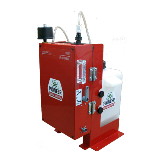
Components: Control unit Pump housing Flow Gauge 20 l Tank 3 Way Valve Harness Inside view Power harness... -
Page 7: Installation Of Applicator
Installation of Applicator: Position on chopper It is recommended for chopper forage harvesters to mount the EZ on the right fender of the harvester. Note: Make sure you can see the flow gauge from the operator’s platform and opening of pump housing should be guaranteed. After finding a sturdy mounting location for the EZ on the fender, use the mounting bracket as a template and drill (4) 7/16”... -
Page 8: Recommended Spray Nozzle Positions
Installation of Applicator: Position on loading wagon/baler It is recommended for loading wagons and balers to mount the EZ on the front side of the harvester or on the drawbar. Note: Make sure you can see the flow gauge from the operator’s platform and opening of pump housing should be guaranteed. - Page 9 Claas Jaguar: 820 – 900 1. Install spray tip, strainer and tubing to nozzle strap. 2. Loose screw from blower and fix nozzle holder inside that hole, ensure central tip position inside the blower. John Deere SPFH (7000 Series) 1. Locate the accelerator. 2.
- Page 10 John Deere SPFH (8000 Series) 1. Locate the blower. 2. Install spray tip, strainer and tubing to nozzle strap. Without removing the nuts, place nozzle strap over existing bolts and nuts (right). Fasten in place with additional nuts and lock-washers. Krone 1.
- Page 11 New Holland FR 1. Locate the blower. 2. Install spray tip, strainer and tubing to nozzle strap. Drill a hole to position the nozzle. Locate the nozzle inside the accelerator, fix outside and ensure central tip position. Chopper Systems not listed For best results on brands/models not mentioned, position nozzle to apply product prior to crop entering knives and blower.
-
Page 12: Plumbing Installation
Option 2: under the drawbar 1. Install spray tip, strainer and tubing to nozzle strap. Bolt the nozzle strap to the feed roll frame with the supplied hardware. Position the nozzle so it sprays directly in front of the feed rolls (50-60 cm above pick-up.) - see picture. Nozzle position under the drawbar Installation of Plumbing... -
Page 13: Harness And Control Installation
To nozzle strap assembly. Installation of Harness and Controls Power / Communication Cable 1. Power harness with orange and black eyeloops is needed. 2. Attach the plug on the harness to the side plug of the EZ cabinet. 3. Run eyeloops down to the 12 volt battery. Check voltage with volt meter before attaching to machines batteries. - Page 14 6. To operate unit using the machines input, press the Liquid Injection Pump Switch ONCE (located on right hand arm rest control panel). All of the following has to be present before the power is supplied to the sprayer: • The road safety switch is in field operating mode.
- Page 15 C. Claas 830 - 990 The following Claas parts are required for the end of row function: • 2337950 Plug • 1787620 Plug pins For Claas choppers (830 - 990), connect the green wire on the tower end of the Intell harness (006-4524M) to the “T”...
-
Page 16: Preparing The Applicator For Operation
Preparing the Applicator for Operation Connect the power harness Attach one end of wire harness (006-4597H) to the side of the applicator. Connect other end to the control box. The power harness (006-4597P) that supplies power from the tractor battery to the applicator will be connected to the control box in the cab. -
Page 17: Operation Of Controls
Operation of the Controls Understanding and using the control The model 457 EZ control is pictured below. The toggle switch (A) is used to supply and cut off power to the pump and compressor. With the switch in the up position (shown) the power is on. Flip switch to down position to turn power off. -
Page 18: Calibration
Calibration for Forage Harvesters, Baggers and Silo Blowers There are two steps that you need to know when calibrating your applicator: determining your ton/hour and using the flow gauge to set the correct pump output. Step 1 Time how long it takes to process a load. Determine how many tons are in a load by weighing it and use the chart below to determine the tons you are processing per hour. -
Page 19: Calibration Reminders
Calibration Reminders Watch the flow gauge, as the setting will vary with tractor’s electrical output, temperature and other factors. *Check your application rate by measuring product used against actual tons processed. REMEMBER, ONLY YOU CAN CONTROL HOW MUCH PRODUCT IS APPLIED AND THAT WILL DETERMINE IF YOUR CROP WILL KEEP! Maintenance •... -
Page 20: Winter Storage
Rebuild pump: Squeeze tube – Replace squeeze tube at the beginning of each season (002-9011→ 30 • Inches). o To replace the squeeze tube; the four front screws need to be removed from the pump. Remove the old tube and place one side of the tube through the top hole leaving an 8- inch section out of the tube. -
Page 21: Troubleshooting
Troubleshooting Problem Possible cause Solution Squeeze Pump Fault in wiring does not start Air leak in intake Replace pump tube Squeeze Pump will Loose compression fitting Tighten nut on fitting 003-JA1414 not prime from tank Missing rubber washer in Replace washer 004-1207W female connector 004-1207H Pump hose is broke Replace pump tube... -
Page 22: Parts Breakdown
Appli-Pro EZ Parts Breakdown 20 Liter Tank Unit Unit Description Part # Mat- Code Base 001-4597T 40552 Tank Lid 6” with Breather 005-9022CX Tank 5 Gallon 005-9210 29871 Wire Harness 006-4597H 40559... -
Page 23: Ez Components
EZ Components Ref# Description Part # Material Code Enclosure, Pioneer EZ 001-4597B 40547 Bottle Holder Bracket 001-4597H 40550 Light Holder Bracket 001-4597L 40551 Door Hinge 001-4597DH 40548 Door Latch 001-4597DL 40549 Black Stop 001-4594 29353 Gauge 002-4597FB 40554 Three Way Valve 002-2213 40553 Injection Motor... -
Page 24: Control Box
Control Box Ref Description Part # Qty Material Code Speed dial 006-2022A U-bracket 001-2012E 20103 Control box knob 008-0923 20181 Control box enclosure 006-2015EZ1 Control box cover 006-2015EZ2 Box Plug (Power) 006-4597ICP Box Plug (Comm.) 006-4597ICH Power Lead 006-4597P 40560 Circuit Board 006-2022P... -
Page 25: Parts Bag
Parts Bag Ref# Description Part # Material Code Tube Installation Tool 007-4523 20176 1/4" x 1/4" Elbow 003-EL1414 20137 1/4" Female Disconnect 004-1207H 22849 Nozzle Holder 001-4216 20104 3/8” Jiffy Clip 008-9012 22873 1/4” x 1 1/4" Self-Tapping HDR-TC-025-0125 25873 Jaco Nut 003-JN14 20142... -
Page 26: Tank Assembly
22852 9/16” Interlocking Nut Washer Hardware 22851 1/4” FPT x 1/4" HB Fitting 003-A1414F 1/4" PVC Tubing 002-9014 20176 1/8”FPT x 1/4"HB Fitting 003-A1814F 20137 ®TM Trademarke of Dow AgroSciences, DuPont or Pioneer and their affiliated companies or respective owners.
Need help?
Do you have a question about the Corteva APPLI-PRO EZ and is the answer not in the manual?
Questions and answers