
Related Manuals for Buhler SZLH-400b


Summary of Contents for Buhler SZLH-400b
- Page 1 Operating Instructions Pellet Mill SZLH - 400b - 420b - 420E - 508b - 508E - 520 SZLH-1-en-1605...
- Page 2 Original Operating instructions Copyright by BCHA...
-
Page 3: Table Of Contents
Table of contents Important information..................... 1 Scope of validity ......................1 Contact........................1 Personnel qualification....................1 1.3.1 Mechanics ....................1 1.3.2 Electricians ....................1 1.3.3 Welders ......................1 Typographical conventions ..................2 1.4.1 Explanation of the warning instructions ............2 Safety ........................ - Page 4 4.4.1 Feeder ......................15 4.4.2 Conditioner ....................16 4.4.3 Die hoist (optional) ..................17 4.4.4 Feed chute....................17 4.4.5 Pellet chamber door ...................17 4.4.6 Pellet chamber ...................17 4.4.7 Gearbox ......................18 Safety system ......................20 4.5.1 Overload protection device .................20 4.5.2 Pellet chamber door protective switch ............20 4.5.3 External discharging ...................20 Safety sign .......................20...
- Page 5 10.3 Lubrication .......................38 Repair ......................... 39 11.1 Die replacement .......................39 11.2 Roller assembly replacement ..................39 11.3 Cleaning of feeder ....................40 11.4 Disassembling and assembling of conditioner ............40 11.5 Disassembling and assembling of die driving key ...........40 11.6 Die repair .........................41 Decommissioning ....................
-
Page 7: Important Information
In case of inquiries, please contact the after-sales service department of man- ► ufacturer. Have the Operation Manual at hand. ► Address ► Buhler (Changzhou) Machinery Co., Ltd. Address: Tianmu Lake Industrial Park, Liyang City, Jiangsu Province, China Tel: +86-519-87966666 Fax: +86-519-87966000 Personnel qualification 1.3.1 Mechanics Personnel that work on mechanical devices must be technically trained or have completed training provided by the manufacturer. -
Page 8: Typographical Conventions
Typographical conventions 1.4.1 Explanation of the warning instructions DANGER Type and source of danger Danger will result in death or serious injury. Actions for protecting against danger. WARNING Type and source of danger Danger can result in death or serious injury. ... -
Page 9: Safety
Safety Designated use SZLH series high-grade pellet mill is the main item of equipment for producing ► feed pellets with application to large and medium scale breeding farm and feed mill. The machine can be fitted with dies of Ø2~Ø10 hole diameter, which can be ►... -
Page 10: Protection Against Unexpected Start-Up
The owner/operator must ensure that the personnel comply with the locally ► valid regulations and laws pertaining to safety and safety-conscious work. The owner/operator must assign responsibilities and tasks and inform person- ► nel of these assignments. Give keys and passwords to authorised personnel only. - Page 11 Operate strictly in accordance with the operation steps and points for attention. ► Overload operation is not allowed thus preventing the failure caused by the such operation. During operation, to avoid injury, opening the pellet chamber door is not al- ►...
-
Page 12: Technical Data
Technical data Environments condition SZLH SZLH SZLH SZLH SZLH SZLH 400b 420b 420E 508b 508E Displacement noise ≤85 ≤85 ≤85 ≤85 ≤85 ≤85 [dB(A)] Die working temperature ≤90 ≤90 ≤90 ≤85 ≤85 ≤85 [℃] Steam working pressure 0.2-0.4 0.2-0.4 0.2-0.4 0.2-0.4 0.2-0.4 0.2-0.4... -
Page 13: Power Date
Power date SZLH SZLH SZLH SZLH SZLH SZLH 400b 420b 420E 508b 508E 110/132/ 110/132/ 110/132/1 Main Motor [KW] 75/90 90/110 90/110 Feeder [KW] Conditioner [KW] 5.5(7.5) 5.5(7.5) 5.5(7.5) 7.5(11) 7.5(11) 7.5(11) Die Rotational Speed [rpm] Feeder Rotational Speed 12-120 12-120 12-120 12-120... -
Page 14: Szlh420B
3.4.2 SZLH420b 1630 1400 211 235 1410 1020 K 向 P 向 185x4=740 Φ12 Fig3.2 SZLH420b Dimension Drawing BCHA Pellet Mill SZLH-1-en-1605 Chapter 3 Technical data... -
Page 15: Szlh420E
3.4.3 SZLH420E 1630 1400 251 235 1410 1020 K 向 P 向 185x4=740 Φ12 Fig3.3 SZLH420E Dimension Drawing BCHA Pellet Mill SZLH-1-en-1605 Chapter 3 Technical data... -
Page 16: Szlh508B
3.4.4 SZLH508b 1630 171 297 1610 1050 K 向 P 向 185x4=740 Φ12 Fig3.4 SZLH508b Dimension Drawing BCHA Pellet Mill SZLH-1-en-1605 Chapter 3 Technical data... -
Page 17: Szlh508E
3.4.5 SZLH508E 1630 171 297 1610 1050 P 向 K 向 185x4=740 Φ12 Fig3.5 SZLH508E Dimension Drawing BCHA Pellet Mill SZLH-1-en-1605 Chapter 3 Technical data... -
Page 18: Szlh520
3.4.6 3.4.6 SZLH520 Fig3.6 SZLH520 Dimension Drawing BCHA Pellet Mill SZLH-1-en-1605 Chapter 3 Technical data... -
Page 19: Description
Description Identification 4.1.1 Specification key SZLH 508b SZLH Code Die ID Index 4.1.2 ATEX ID for use in Ex zone 22 The ATEX ID indicates the conditions required for integrating the machine into an Ex zone or connecting the machine to an Ex zone. II */3D T=125 °C Explanation of symbols: —... -
Page 20: Atex Id Without Approval For Potentially Explosive Zone
— Maximum expected surface temperature in °C in normal operation at full load with an ambient temperature of T — Increased ambient temperature in °C — Temperature class: Maximum surface temperature 200 °C — Instructions in the Operating instructions for maintaining explosion protection equipment are indicated with the Ex symbol. -
Page 21: Overview
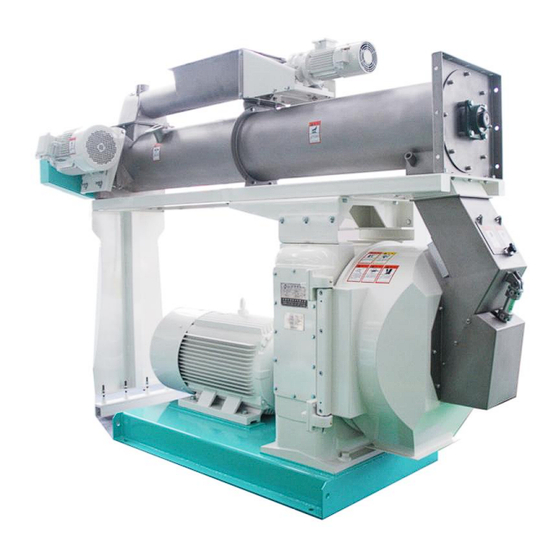
Overview 1.Mill Base 7.Bearing 13. Conditioner Support 2.Gear Box 8.Knife Mechanism 14. Main Motor 3.Chamber Door 9.Motor 15. Overload Limit Switch 4.Feed Chute 10.Feeder 16. Coupling Guard 5.Safety Switch 11.Steam inlet 17. Coupling 6.inspection Window 12.Bearing 18. Oil Drain Valve Fig. -
Page 22: Conditioner
Reducer Feeder reducer adopts cycloidal pin gear reducer whose reducing ratio is 1:17. ► It is directly connected with speed-adjusting motor to reduce the speed and make feeder capable of being adjusted for speed with effective rotational speed 12-120rpm. Feeder See Figure 4.2 for the structure of feeder. -
Page 23: Die Hoist (Optional)
4.4.3 Die hoist (optional) It is used to facilitate the removing and mounting of die and roller. Worm gear and worm are used for driving. To use the die hoist, pull out the guide and use bolts to connect the holes in the hoist and thread holes in the die. 4.4.4 Feed chute It consists of bearing, external discharge mechanism, handle, inspection door, shell,... -
Page 24: Gearbox
two opposite rotating parts press mash feed gradually into die holes. Feed shapes in die holes and is pressed out of die holes continuously, then the pel- leted feed is cut to required length by knives and finally the shaped pellet feed flows out of the machine. - Page 25 1. Seal 12. Spacer 22. Gear Key 2. Sleeve 13. Main Shaft 23. Quill Shaft 3. Bearing 14. Outer Roll Support 24. Bearing 4. Pinion Shaft 15. Rear Wiper 25. Seal 5. Seal Cover 16. Seal 26. Shear Pin Housing 6.
-
Page 26: Safety System
Safety system The safety system consists of overload protection, pellet chamber door protective switch and external discharge of meal. 4.5.1 Overload protection device When any foreign hard materials enter the pelleting area, or the feed flow rate is in excess, the pressure between die and rollers will exceed the normal design work- ing torque for the main shaft, and thus the shearing force transmitted to shear pin will exceed its shear strength and the shear pin will break. - Page 27 Hot material and steam will cause serious damage , please open the door after close the steam and the material getting cool. Pull the knife out before you open the door, other it will cause damage to the door , when close the door the knife should be postion again at the right position.
-
Page 28: Transport
Transport Packaging symbols 1、This side up 2、Protect from moisture 3、Centre of gravity 4、Fragile 5、Attach here Observe the packaging symbols. ► Checking the delivery Check the delivery for completeness according to the delivery note. ► Report any missing parts or transport damage. See Chapter "1.2 Contact". ►... - Page 29 When it is stored outdoors, there should be facilities to prevent rain, sun and ► water accumulation. When it is stored indoors, there should be good ventila- tion and facilities to preventing dampness and dust. See Figure 5.1 for lifting. ►...
-
Page 30: Installation
Installation Pellet mill installation The technological process should be considered when planning the installation of the pellet mill, (feeding, discharging, cooling, etc), and the required floor space should be determined to ensure suitable service area for staff to operate press and open the pellet chamber door. -
Page 31: Discharge Opening
SZLH400 400 500 200 120 1410 1800 950 1300 4-M24×500 50 700 500 4-100×100 SZLH420 400 500 200 120 1410 1800 950 1300 4-M24×500 50 700 500 4-100×100 SZLH508/520 400 500 200 120 1610 2000 1000 1300 4-M24×500 50 700 500 4-100×100 Fig. -
Page 32: Oil And Molasses Adding System
Item Name Size Remark Stop valve Dg50 Pressure gage 3/8 " Pressure 0-10bar,Meter Dia:Ø100mm Pressure meter 3/8 " switch The annular siphon 3/8 " The annular siphon Stop valve Dg40 educing valve Dg40 pressure : 0.05-0.4MPa(Yellow Spring) Steam separator DN65 Flange(DIN PN16)... -
Page 33: Electric Control System
should not exceed 3%, otherwise pellet quality will be affected. If the required addi- tional amount is 3%-6%, oil and molasses can be atomized and sprayed after pel- leting. Electric control system See Figure 6.4 for electric control system and Table 6.1 for list of components. It is used only for installation of single machine. - Page 34 Fig. 6.4 Electrical Principle Diagram BCHA Pellet Mill SZLH-1-en-1605 Chapter 6 Installation...
-
Page 35: Commissioning
Commissioning Putting the subassembly into operation 7.1.1 Die-roller clearance adjustment Open the pellet chamber door, loosen the fastening bolts of the feed cone (See Figure 12), hold two handles of feed cone tightly with hands, turn the feed cone clockwise, thus feed cone can be removed. Then clear away the accumulated ma- terial on the inside surface of die (1) and surface of rollers (3), loosen lock screws (2) and retaining nuts (6), twist the adjusting screw (7) so as to make the roller ad- justing quadrant (10) turn. -
Page 36: Knife Adjustment
It is very important to control die-roller clearance correctly. Too small clearance will severely wear rollers and die, too large clearance will affect the output and even pelleting effect. Generally clearance should be 0.05-0.3mm. Clearance between new die and rollers can be measured with feeler gauge. If adjusting the clearance during ordinary production, control clearance to the following manner: when turning die with hands, rollers rotate intermittently and just touch the die through visual in- spection. -
Page 37: Adjustment Of Angle Of Conditioner Paddles
tional speed is mounted on the controller for determining the speed value objec- tively. During the normal operation, the variation of working current of main motor should be observed when adjusting the rotational speed of the feeder. When speed and product output are increasing, the working current of main motor must not ex- ceed the rated value (Refer to the rated value stipulated on the nameplate of main motor). -
Page 38: Operation
Operation Test run After installing the machine, make a trial run first. The steps of trial run are as fol- lows: Check to see whether fastening of all parts is secure, especially in the pellet ► chamber. Fill lube according to Lubrication Diagram. Lube inside rollers can be filled af- ►... -
Page 39: Operation
WARNING Do not insert anything (including hands) into pellet mill during the running of pellet mill. Operation 8.2.1 Starting steps Make a good preparation in accordance with Item 4.3.1 to Item 4.3.9 before ► starting the machine. Only after confirming that all parts of the machine are normal can operator carry out formal run in accordance with the following se- quence of steps. -
Page 40: Use Conditions
Feed appropriate oily feed through the inspection door to fill up the die Holes, ► thus preserving the die holes & ensuring future best start-up conditions. Turn off the main motor. ► Open the pellet chamber door after press stops and clear away the accumu- ►... -
Page 41: Troubleshooting
Troubleshooting Fault Cause Remedy Mash feed can enter Die holes block. ► Clear die holes with corre- the pellet chamber sponding drill. normally, but no pellet Moisture is too much or ► Adjust the steam amount can be produced. too little. correctly. - Page 42 Fault Cause Remedy Small hard foreign ma- ► Clear away the foreign terials enter the die materials in die holes. holes. Output doesn’t meet Moisture is not suitable. ► Adjust steam amount ac- the requirement. cordingly. There is problem with ►...
-
Page 43: 10 Maintenance
10 Maintenance 10.1 Everyday maintenance Follow Figure 10.1 strictly to inject grease to each lubricating point. The high tem- perature - resistant lube should be injected even more to rollers through the end of main shaft in accordance with the stipulation. View K K向... -
Page 44: Lubrication
For the gearbox and reducer, oil should be changed after the initial 500 hours ► of operation, later oil should be changed once about every half a year of con- tinuous operation (about 1000 hours). The bearings of feeder and conditioner should be dismounted for cleaning and ►... -
Page 45: 11 Repair
11 Repair 11.1 Die replacement When the inside surface of die has worn to the bottom of the groove at the track width edge or pellet diameter needs to be changed, it is necessary to replace die. The replacing steps are as follows: Open the pellet chamber door. -
Page 46: Cleaning Of Feeder
Hit the outer ring and spacer out of two bearings with special-purpose big ► bush and hammer. Check the use condition of bearing and other parts. Replace bearing and oth- ► er parts according to the degree of wear. Clean the full set of roller assembly and re-assemble roller according to the ►... -
Page 47: Die Repair
11.6 Die repair When the inside surface of die wears seriously and the reverse taper of die hole wears to flat, the inside surface of die can be ground. When clamping the die, try best to ensure the coaxial degree and vertical degree of die datum plane and in- side hole. -
Page 48: 12 Decommissioning
12 Decommissioning 12.1 Shutting down Note Granulator when using, also should be prescribed to step off the car, shall not be taken lightly, in order to avoid misoperation cause equipment accident。 Shut off the feeder gate。 Turn the feeder to the lowest speed, turn off the steam valve accordingly Shut off the feeder and conditioner Motor when there is no product from the inspection gate. -
Page 49: 13 Spare Parts
13 Spare parts 13.1 Inventory of spare parts Stocking a supply of spare and wear parts is an important prerequisite for the ma- chine to remain up and running. Always use original spare parts as listed in the Spare parts catalog. Spare parts from third-party providers can have an adverse affect on the operating behaviour of the machine and on safety. -
Page 50: Spare Parts Lists
13.4 Spare parts lists 13.4.1 Common wearing parts for SZLH400、SZLH420 Item Name Size Position Pellet Chamber(.4-16) Roller Pellet Chamber(.4-1) Roller shaft Pellet Chamber(.4-4) Die Clamp Pellet Chamber(.4-25) Wear Ring Pellet Chamber(.4-14) Die Driving Key Pellet Chamber(.4-24) Shear Pin Shear Pin Housing(.4-36) Knife Knife Mechanism(.8-1)... -
Page 51: 13.4.2 Common Wearing Parts For Szlh508
Item Name Size Position Paddle(long) Conditioner (.3.2-2) Paddle(short) Conditioner (.3.2-4) 13.4.2 Common wearing parts for SZLH508 Item Name Qty/st Position Pellet Chamber (.4-16) Roller Pellet Chamber (.4-51) Roller shaft Pellet Chamber (.4-4) Die Clamp Pellet Chamber (.4-24) Wear Ring Pellet Chamber (.4-15) Die Driving Key Pellet Chamber (.4-22) Shear Pin... - Page 52 Item Name Qty/st Position 35 Paddle(long) Conditioner (.3.2-2) 36 Paddle(short) Conditioner (.3.2-4) BCHA Pellet Mill SZLH-1-en-1605 Chapter 13 Spare parts...
-
Page 53: 14 Attachment
14 Attachment 14.1 Shear Pin 14.1.1 SZLH400b φ 33 2-0.5×45° -0.02 φ 20f7( -0.041 φ 15 1×45° 标记 75KW 90KW Motor power 11±0.1 12±0.1 Signa Material Q235-A Fig. 14.1 SZLH400b shear pin BCHA Pellet Mill SZLH-1-en-1605 Chapter 14 Attachment... -
Page 54: 14.1.2 Szlh420B
14.1.2 SZLH420b φ 33 2-0.5×45° -0.02 φ 20f7( -0.041 φ 15 1×45° 标记 Motor power 12±0.1 13.2 Signa Material Q235-A Fig. 14.2 SZLH420b shear pin BCHA Pellet Mill SZLH-1-en-1605 Chapter 14 Attachment... -
Page 55: Szlh508/520
14.1.3 SZLH508 φ 23.9 -0.21 2×45° 1×45° R2.5 φ 25 -0.05 2×45° 标记 Motor Power 11.5±0.1 12.7±0.1 14.5±0.1 Signa Material Q235-A Fig. 14.3 SZLH508/520 shear pin BCHA Pellet Mill SZLH-1-en-1605 Chapter 14 Attachment...
Need help?
Do you have a question about the SZLH-400b and is the answer not in the manual?
Questions and answers