Table of Contents
Advertisement
Quick Links
Advertisement
Table of Contents

Related Manuals for Pentair Pro-Source PSC Series


Summary of Contents for Pentair Pro-Source PSC Series
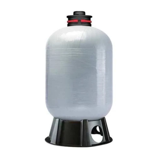
- Page 1 OWNER’S MANUAL Composite Pressurized Water Tanks 293 Wright Street, Delavan, WI 53115 PSC Series Installation/Operation/Parts For further operating, installation, or maintenance assistance: Tested and Certified by the WQA Call 1-262-728-9181 to NSF/ANSI Std. 61 Section 8 CH20463 (02/17/12) © 2012...
- Page 2 LIMITED WARRANTY PENTAIR WATER warrants to the original consumer purchaser (“Purchaser” or “You”) of the products listed below, that they will be free from defects in material and workmanship for the Warranty Period shown below.
-
Page 3: General Safety
Safety Tanks To prevent possible serious or fatal injury and/or damage to equipment, system pressure must be less than 125 pounds per square inch gauge (psig) under any circumstances. Failure to follow this instruction can result in tank explosion. If system discharge pressure can exceed 125 psig, install a relief valve capable of pass- ing the full pump volume at 125 psig. -
Page 4: Installation
Operation / Installation Chart II – Water Yield Per Pump Cycle NOTICE: When replacing a standard tank in a sub- mersible pump system, raise pump and discharge pipe (drawdown) in Gallons far enough to remove bleeder orifices from the tees in Tank the discharge pipe. -
Page 5: Air Cell Replacement
Installation TO CHECK TANK AIR CHARGE B. Reconnect power supply to pump and pump up pressure in system. If drawdown (amount of water that comes out of tank C. Disconnect power supply to pump again and re- per pump cycle) decreases significantly, check as check switch setting. - Page 6 Installation 6. Air cell may not come out in one piece. Pull air cell 9. Shake air cell a few times inside tank to work wrin- up with pliers and cut wherever convenient with sin- kles out. It is not necessary to remove all wrinkles gle edge razor blade or sharp knife.
- Page 7 Installation To Household Water System Relief Valve Check Valve Pressure Switch 5895 1008 From Well Figure 7:Typical Installation with Jet Pump Pressure Pressure Switch Pressure Gauge Gauge Relief Relief Valve Valve Service Service 1 0 0 Floor Drain 5896 1008 Floor Pressure Drain...
-
Page 8: Repair Parts List
Repair Parts REPAIR PARTS LIST Part Part Description Qty. Number Polar Boss Cap Kit (includes CH20294K Key Nos. 1, 2, 3, 4, 5, 6) Pole Piece Cap Valve Stem Nut Washer C-Clip Polar Boss Cap O-Ring Base See below Elbow Adapter Kit (includes See below Key Nos.
Need help?
Do you have a question about the Pro-Source PSC Series and is the answer not in the manual?
Questions and answers