
Related Manuals for Siemens ISGS


Summary of Contents for Siemens ISGS
- Page 1 sales@artisantg.com artisantg.com (217) 352-9330 | Visit our website - Click HERE...
- Page 3 The contents of the instruction manual shall not become part of or modify any prior or existing aggreement, commitment or & relationship. The sales contract contains the entire obligation of Siemens Energy Automation, Inc. The warranty contained in &...
-
Page 4: Table Of Contents
3.12.4 Configure Communications Port Power On/Configuration SEAbus (Address 7200) 3.6.1 Initial Power On Display Power On Meter Display 3.6.2 Device and Protective Function Configuration 3.7.1 Device Configuration (Address 1000)_ 19 Windows is a trademark of Microsoft Corp. & Siemens Energy Automation, Inc. - Page 5 Meterin g Accuracy Power Conventions Appendix C Schematics DC Trip System Breaker Monitorin g Features C.2.1 Trip Coil Continui ty Monitorin g C.2.2 Trip Source Impeda nce Monito ring AC (Capac itor) Trip System s Siemens Energy & Automation, Inc.
- Page 6 - indicates a potentially hazardous situation could which, if not avoided result in death or serious The ISGS™ relay is designed and manufactured in accor injury. dance with the latest provisions of the applicable IEEE, ANSI and NEMA standards. You must thoroughly read and under...
-
Page 7: Seabus Communication Interface
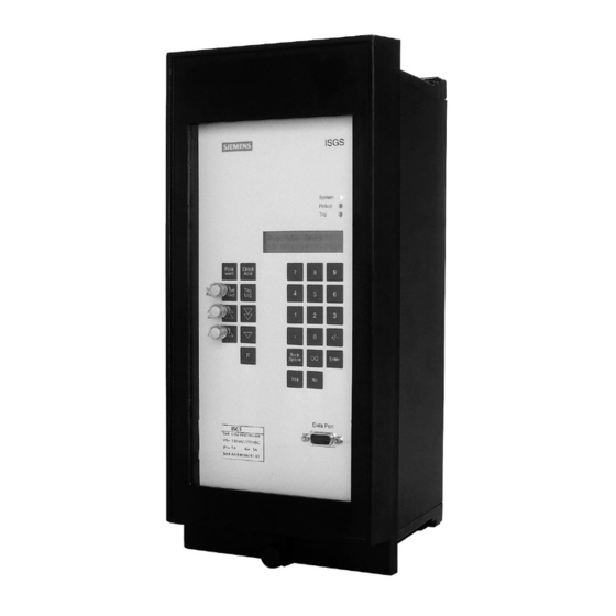
Wisdom software can also display real-time relay status and metering data. The ISGS relay includes a 2 line by 16 character liquid crys tal display (LCD) for viewing measured data and a 28 button Installation and use of the Wisdom program is extremely keypad for local access to the data. -
Page 9: Installation
Use this interface lever to the left and the bottom release lever to the right to perform initial setup or to read the ISGS relay data logs or until the assembly ejects from the case. -
Page 11: Configuration
at ion Major Addr. Block Function Requ1re d operation steps Remarks 1-14 Device configuration Note 1 1100 CT configuration Note 1 1200 configuration Note 1 1400 Breaker Statistics 1500 Phase configuration 1600 50 Neutral or groun d configuration 1700 51 Phase configuration 1800 Neutral or groun nfiguration... -
Page 20: Alarm Setpoints (Address 3000)
For the power factor setpoints, the sign of the pickup value (leading or lagging) 32 1 4 Time Delay 0 - 3600 s Table may be specified. 3.20 Power Parameter Configu ration, M ajor block 3200 Siemens Energy & Automation, Inc. -
Page 31: Overvoltage Equations
655.35 1 . 1 20. 00 0.01 . The ISGS relay provides aa moderately inverse undervoltage has a range of in steps of The first characteristic that is defined by the following equation: point in the data set must be ilip... - Page 32 Multiples of Pickup Figure Figure Long Inverse (SEA 3) Inverse (SEA 1 ) � � <1) <1) � <1) <1) 1. 5 • Multiples Pickup Multiples of Pickup Figure Figure Moderately Inverse (SEA 4) Short Inverse (SEA & Siemens Energy Automation, Inc.
- Page 34 Figure A.1 1 Moderately I nverse Undervoltage Figure A.9 t Without Limit (SEA 9) � 1 00 � 1 .2 1 .4 Multi p les p icku p Figure A.1 0 Moderately Inverse Overvoltage & Siemens Energy Automation, Inc.
-
Page 35: Appendix
Note for all values: Stated accuracy applies only when the device is not in pickup. These measurements are valid over a fre quency range of 45 65 Hz and include fundamental, 2nd harmonic, and all odd harmonics up to the 1 3th harmonic of the fundamental line frequency. & Siemens Energy Automation, Inc. - Page 41 Box 29503 P.O . Raleig h , NC 27626-0503 Manual No. SG-8058-01 (Replaces SG-8058) © 1 995 Sieme n s Energy & Automation, I n c. Printed in U. S.A. 2M0795SP SIEMENS is a registered trademark of Sieme n s AG...
Need help?
Do you have a question about the ISGS and is the answer not in the manual?
Questions and answers