Table of Contents
Advertisement
Quick Links
Instructions
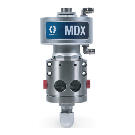
MDX Dispense Valve
Dispense valve for controlling material flow of adhesives, sealants, and other materials
that are compatible with the wetted parts of the valve. For professional use only.
Not approved for use in European explosive atmosphere locations.
Model 26D274
3/4 in. npt Dispense Valve
3000 psi (20.68 MPa, 206.8 bar) Maximum Fluid Working Pressure
100 psi (0.7 MPa, 7 bar) Maximum Air Working Pressure
Important Safety Instructions
Read all warnings and instructions in this
manual before using the equipment.
Save these instructions.
3A8814A
EN
Advertisement
Table of Contents

Related Manuals for Graco 26D274


Summary of Contents for Graco 26D274
- Page 1 For professional use only. Not approved for use in European explosive atmosphere locations. Model 26D274 3/4 in. npt Dispense Valve 3000 psi (20.68 MPa, 206.8 bar) Maximum Fluid Working Pressure 100 psi (0.7 MPa, 7 bar) Maximum Air Working Pressure...
-
Page 2: Table Of Contents
California Proposition 65 ....21 Graco Standard Warranty ....22... -
Page 3: Warnings
Warnings Warnings The following warnings are for the setup, use, grounding, maintenance, and repair of this equipment. The exclamation point symbol alerts you to a general warning and the hazard symbols refer to procedure-specific risks. When these symbols appear in the body of this manual or on warning labels, refer back to these Warnings. Product-specific hazard symbols and warnings not covered in this section may appear throughout the body of this manual where applicable. - Page 4 Warnings WARNING FIRE AND EXPLOSION HAZARD Flammable fumes, such as solvent and paint fumes, in work area can ignite or explode. Paint or solvent flowing through the equipment can cause static sparking. To help prevent fire and explosion: • Use equipment only in well-ventilated area. •...
-
Page 5: Component Identification
Component Identification Component Identification . 1: 3/4 in. npt Dispense Valve - Typical Components Key: Air Connections Air Section Travel Adjuster Lock Nut Fluid Section Recirculation Port Plug A Recirculation Port Plug B Fluid Outlet Fluid Inlet A Fluid Inlet B Grease Zerk Fittings 3A8814A... -
Page 6: Theory Of Operation
Theory of Operation Theory of Operation The valve uses the air-opened and air-closed mode of The air-operated piston, rod, and ball move at the same operation, therefore, it uses a four-way exhausting time. When air moves the piston, rod, and ball from their solenoid to control the piston inside the valve. -
Page 7: Installation
Installation Installation Grounding Flush Before Using Equipment The equipment was tested with lightweight oil, which is left in the fluid passages to protect parts. To avoid contaminating your fluid with oil, flush the equipment with a compatible solvent before using the equipment. The equipment must be grounded to reduce the risk of static sparking. -
Page 8: Mounting
Installation Mounting 6. Check each fitting to avoid pressure leakage from the dispense valve. The dispense valves have multiple mounting hole configurations (see Dimensions, page 20), which make them ideal for use with robotic equipment or multiple manifold high production operations. 1. -
Page 9: Operation
Operation Operation Pressure Relief Procedure Adjust Stroke Adjust the distance that the dispense valve opens to Follow the Pressure Relief Procedure whenever restrict the flow of material through the ball and seat. you see this symbol. See Fig. 4. 1. Loosen the lock nut (D). 2. -
Page 10: Maintenance
Maintenance Maintenance Packing Lubrication Inspect the dispense valve, material, and air hoses at least once every two weeks. Inspect for leakage and other visible damage daily. If there is any leakage or damage, change the part immediately. Follow the Repair, on page 14. The following table lists recommended maintenance This valve has a primary seal, a pressurized grease procedures and frequencies. -
Page 11: Factors Affecting Valve Life
Maintenance Factors Affecting Valve Life The maintenance tables should be used as a guideline for maintenance frequency. Additional factors that could affect valve life include the following: • Process Fluid - Abrasive or fiber filled fluids are much harder on seals, shafts, and seats than non-abrasive fluids, such as oil. -
Page 12: Recycling And Disposal
Recycling and Disposal Recycling and Disposal End of Product Life At the end of the product’s useful life, dismantle and recycle it in a responsible manner. • Perform the Pressure Relief Procedure, page 9. • Drain and dispose of fluids according to applicable regulations. -
Page 13: Troubleshooting
Troubleshooting Troubleshooting 1. Follow Pressure Relief Procedure, page 9, before checking or repairing the valve. 2. Check all possible problems and causes before disassembling valve. Problem Cause Solution Air leaks from dispense valve. Loose air connections. Check air connections. Worn o-rings. Replace o-rings in air housing. -
Page 14: Repair
Repair Repair Disconnect NOTE: Always replace o-rings after the valve has been disassembled. If the valve is hot, wait for it to cool completely before determining whether or not you can repair it. Some materials, like polyurethanes, may cure permanently when cooled and exposed to air, preventing you from disassembling the dispense valve. -
Page 15: Disassembly
Repair Disassembly 6. Place a wrench on the ball (106) flats. Remove two balls from the piston rod. 1. Perform the Disconnect procedure, on page 14. 2. Remove four o-rings (114a and 134), two seats (133) and two gaskets (132). 114b 114a 7. -
Page 16: Assembly
Repair Assembly NOTICE To prevent the ball from loosening and causing equip- 1. Install new o-rings (118, 117) on the piston rod ment damage, allow the anaerobic adhesive to set for assembly (103) and in the air housing (102). See 24 hours before running the valve. -
Page 17: Parts
Parts Parts 3/4 in. npt Fluid Section 114 1 Apply a thin coat of lubricant to surface. Torque to 40-45 ft-lbs (54.2-61.0 N•m). Torque to 30-35 ft-lbs (40.7-47.5 N•m). Ref. Part Description Qty. HOUSING, fluid section, MDX HOUSING, outlet, MDX, 1 npt SCREW, shc, M12 x 1.75 x 110, CS, zinc 18F418 FITTING, lubrication, st... -
Page 18: 3/4 In. Npt Air Section
Parts 3/4 in. npt Air Section Apply a thin coat of lubricant to surface. Torque to 40-45 ft-lbs (54.2-61.0 N•m). Torque to 30-35 ft-lbs (40.7-47.5 N•m). Apply thread sealant to threads. Ref. Part Description Qty. HOUSING, air section, MDX 26D312 PISTON ROD, assy, MDX CAP, air, adjustable, 3/4 in. -
Page 19: Accessories
Accessories Accessories Before installing any accessories, perform the Pres- sure Relief Procedure, on page 9. Grease Gun, 551189 Use to pump grease into the zerk fitting. Mixer, 513375 Mixer thread: 3/4 in. npt (m), with factor. Fitting, 122639 Swivel, 1 nps x 1/4 npt, ff, ms, 3k, stainless steel 2.34 in (59.4 mm) 1-11 1/2 npt (f) -
Page 20: Dimensions
Dimensions Dimensions 3/8 in. OD tubing; push to connect fitting 5.72 in (145.3 mm) 4 x M5 x 0.8 depth 0.38 in. (9.65 mm) 11.625 in (295.3 mm) 0.73 in (18.5 mm) 1.06 in (26.9 mm) 4.08 in 3.35 in (103.6 mm) (85.1 mm) 3/4 npt (f) -
Page 21: Technical Specifications
Technical Specifications Technical Specifications MDX Dispense Valve Metric Maximum air working pressure 100 psi 0.7 MPa, 7 bar Maximum fluid working pressure 3000 psi 20.68 MPa, 206.8 bar Maximum fluid operating temperature 158 °F 70 °C Weight 26.79 lb 12.15 kg Stainless steel, tungsten carbide, chemical resistant Wetted materials on all models fluoroelastomer rubber, UHMWPE... -
Page 22: Graco Standard Warranty
With the exception of any special, extended, or limited warranty published by Graco, Graco will, for a period of twelve months from the date of sale, repair or replace any part of the equipment determined by Graco to be defective.