Table of Contents
Advertisement
Quick Links
1 ANI-1F6-A
Module for process control in CO
1.1
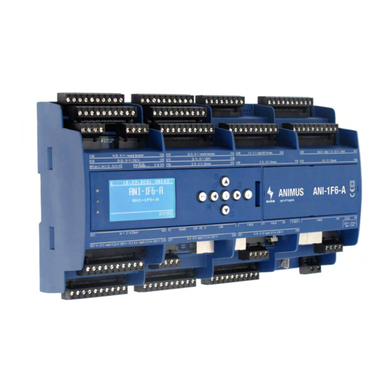
Front view
Fig. 1: Front view with ANI-C control panel
1.2
Features
•
2 standard rack controllers (MT and LT), each with 3 compressors controlled by evaporation tem-
perature
-
Compressor 1 constant (FC), compressors 2 and 3 stepped
-
T
sliding via HLO003
0
-
Simple base load change
-
Monitoring of suction gas temperature
-
Oscillation protection function
-
Blocking time after compressor fault
-
3-step load shedding including Fastreturn for MT/LT
-
Operating hours counter and cycle counter for each compressor
•
High pressure and medium pressure control
•
Gas cooler fan control also via Modbus
•
Additional control circuits for:
-
Load shedding
-
Desuperheater
-
Liquid post-injection
-
Refrigerant monitoring
-
Heat recovery
•
Integrated relay outputs
•
CAN bus connection via patch cable and screw terminals
•
Fastening by top-hat rail
•
Can be locked to prevent unwanted parameter adjustment
•
Connection to the Wurm system via Wurm CAN communication bus (C-BUS) and
FRIGODATA XP
Accessories
•
Control panel (ANI-C)
ANI-1F6-A_V1.0.0_PI_2021-08_EN
refrigeration plants with rack and gas cooler control
2
Subject to technical changes
FRIGOLINK
ANI-1F6-A
1
Advertisement
Table of Contents

Related Manuals for WURM FRIGOLINK ANI-1F6-A


Summary of Contents for WURM FRIGOLINK ANI-1F6-A
-
Page 1: Ani-1F6-A
CAN bus connection via patch cable and screw terminals • Fastening by top-hat rail • Can be locked to prevent unwanted parameter adjustment • Connection to the Wurm system via Wurm CAN communication bus (C-BUS) and FRIGODATA XP Accessories • Control panel (ANI-C) ANI-1F6-A_V1.0.0_PI_2021-08_EN... -
Page 2: Table Of Contents
FRIGOLINK ANI-1F6-A Contents ANI-1F6-A ..........1 1.1 Front view . -
Page 3: Safety Instructions
Wurm GmbH & Co. KG Elektronische Systeme. Keep these instructions ready to hand for quick reference and pass them on with the device if the product is sold. - Page 4 Any software versions not listed are special solutions for individual projects and are not described in detail in this document. This document automatically ceases to be valid if a new technical description is issued. Manufacturer: Wurm GmbH & Co. KG Elektronische Systeme, Morsbachtalstraße 30, D-42857 Remscheid You can find more information on our website at www.wurm.de.
-
Page 5: Circuit Diagram
FRIGOLINK ANI-1F6-A Circuit diagram Fig. 2: Circuit diagram Power supply Terminal Power supply Potential Neutral 230V~ Functional earth (FE) Terminal Assignment Shield • To ensure failure-free operation and reliable data communication, connect the functional earth. NOTICE Connect the functional earth connection via the enclosed earthing terminal and the pre-assem- bled cable directly to the device with the earthed installation plate. -
Page 6: Input Circuit Diagram
FRIGOLINK ANI-1F6-A 1.4.1 Input circuit diagram Fig. 3: Input circuit diagram Digital inputs DI 1 - DI 20 Terminal Digital input Potential Assignment DI 1 230V~ MT CP 1 operation DI 2 230V~ MT CP 2 operation DI 3 230V~ MT CP 3 operation DI 4 230V~... -
Page 7: Analogue Inputs Uin 1, 2
FRIGOLINK ANI-1F6-A Terminal Digital input Potential Assignment DI 15 230V~ MT rack LP fault DI 16 230V~ MT rack HP fault DI 17 230V~ LT rack LP fault DI 18 230V~ LT rack HP fault DI 19 230V~ GC fan fault DI 20 230V~ MT load shedding 1... -
Page 8: Analogue Inputs S 1 - S 16
FRIGOLINK ANI-1F6-A Analogue inputs S 1 - S 16 Terminal Sensor input Sensor type Assignment 161/162 Suction gas tempera- ture MT 163/164 Pressure gas temper- ature MT 165/166 Desuperheating tem- perature LT 167/168 Outside temperature 169/170 T.gc 1 171/172 T.gc 2 173/174 Outlet temperature HR CO2 *... -
Page 9: Output Circuit Diagram
FRIGOLINK ANI-1F6-A 1.4.2 Output circuit diagram Fig. 4: Output circuit diagram Digital outputs (relays) K 1 - K 14 Contact arrange- Terminal Digital output Assignment ment Change-over contact Alarm output prio 1 K 1 / (NC) 4(2)A / 230V~ Change-over contact Alarm output prio 2 K 2/ (NC) -
Page 10: Digital Outputs (Ssr) V 1 - V 4
FRIGOLINK ANI-1F6-A Contact arrange- Terminal Digital output Assignment ment NO contact K 13 / IHE oil SV 3(1)A / 230V~ NO contact K 14 / Control cabinet fan 3(1)A / 230V~ * The digital outputs are active if the assignment is set to ANIMUS under Heat recovery in the installa- tion level. -
Page 11: Communication Circuit Diagram
FRIGOLINK ANI-1F6-A 1.4.3 Communication circuit diagram Fig. 5: Communication circuit diagram Communication Terminal Potential Assignment C-BUS F-BUS RS 485 (Modbus) ANI-1F6-A_V1.0.0_PI_2021-08_EN Subject to technical changes... -
Page 12: Fkv003 Circuit Diagram
FRIGOLINK ANI-1F6-A 1.4.4 FKV003 circuit diagram Fig. 6: FKV003 circuit diagram Address 0 Terminal Sensor input Sensor type Assignment 21/22 HP defrost tempera- ture 22/23 HP suction gas tem- perature 24/25 Outlet temperature HR medium * 25/26 Inlet temperature HR medium * 44/45/46/47 4...20mA/0...10V... -
Page 13: Address 1
FRIGOLINK ANI-1F6-A Address 1 Terminal Sensor input Sensor type Assignment 21/22 Outlet temperature HR CO2 * 22/23 Temperature ext. heat source * 24/25 Air conditioning out- let temperature Air conditioning inlet 25/26 temperature 44/45/46/47 4...20mA/0...10V -0.5...7bar Water pressure Terminal Input Assignment 36/39 DI 1... -
Page 14: Fio001B/Fio-Pat Circuit Diagram
FRIGOLINK ANI-1F6-A 1.4.5 FIO001B/FIO-PAT circuit diagram Fig. 7: FIO-PAT circuit diagram Address 2 Terminal Sensor input Sensor type Assignment 16/17 Shop temperature 14/15 Air conditioning suc- tion gas temperature 11/12/13 0...60bar Air conditioning evap- orator p0 Terminal Input Assignment 21/22 DI 1 Not available 21/23... -
Page 15: Installing
FRIGOLINK ANI-1F6-A Installing The module is designed for top-hat rail installation. The housing is also suitable for installation in fuse boxes or distribution switch cabinets. Modules can be positioned side by side without gaps. DANGER TO LIFE FROM ELECTRIC SHOCK AND/OR FIRE! WARNING •... -
Page 16: Dismantling
FRIGOLINK ANI-1F6-A Dismantling 1. Insert a flat-tip screwdriver in the openings in the fastening safety catches. 2. Pull the two fastening safety catches away from the housing until they are heard to click. 3. Swivel the bottom of the module gently away from the top-hat rail and towards yourself. 4.
Need help?
Do you have a question about the FRIGOLINK ANI-1F6-A and is the answer not in the manual?
Questions and answers