Advertisement
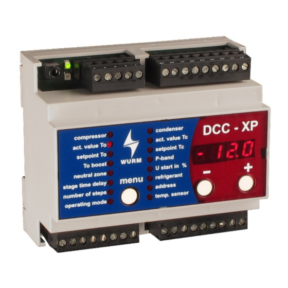
Front view
Features
4 capacity steps for different compressor types:
- Equally or unequally graduated compressors
- 1-, 2- or 3-step compressors
- With or without cylinder lift
- Same compressors with a constant compressor via CFU
Extendable by 4 capacity steps with one additional DCC-XP
Compressor downtime monitoring and rack downtime monitoring
Base load change according to run time and switching frequency
Operating hours counter for each compressor step
Peak load shedding and Fastreturn
Operating mode for controlling compressor output through voltage input
Suction pressure increase through switch contact
Constant condensation pressure control by speed regulator or ADC multiple
contact switch
Cyclical forced start-up for condenser fans
Peak load limiting
Temperature sensor TRK277/7 PLUS for outside temperature guided
condensation setpoint, for suction gas monitoring or temperature
documentation, with/without failure monitoring as desired
Display of current operating status of the refrigeration plant
Direct connection of a CAN-USB to the service socket
Connection to the Wurm system via Wurm CAN communication bus (C-BUS)
and FRIGODATA XP
DCC-XP_V6.5.0_PI_2021-08_EN
with integrated condensation pressure control
Subject to technical changes
DCC-XP V6
Rack control
Page 1 of 4
Advertisement
Table of Contents

Related Manuals for WURM DCC-XP V6


Summary of Contents for WURM DCC-XP V6
- Page 1 Display of current operating status of the refrigeration plant Direct connection of a CAN-USB to the service socket Connection to the Wurm system via Wurm CAN communication bus (C-BUS) and FRIGODATA XP DCC-XP_V6.5.0_PI_2021-08_EN...
- Page 2 Wurm GmbH & Co. KG Elektronische Systeme. Keep these instructions ready to hand for quick reference and pass them on with the device if the product is sold.
- Page 3 DCC-XP V6 Rack control with integrated condensation pressure control Circuit diagram C-BUS interface Output relay Pressure sensor Digital inputs Installing and connecting WARNING Danger to life from electric shock and/or fire! Switch off the power to the entire plant when carrying out installation, wiring or removal work.
- Page 4 DCC-XP V6 Rack control with integrated condensation pressure control Place the device with the upper guide edge on the top-hat rail. Then press the device gently downward until it engages with the fastening safety catch on the top-hat rail. For wiring of the data lines, we recommend the use of standard telephone lines 2x2x0.8ø up to lengths of 100m.
Need help?
Do you have a question about the DCC-XP V6 and is the answer not in the manual?
Questions and answers