Advertisement
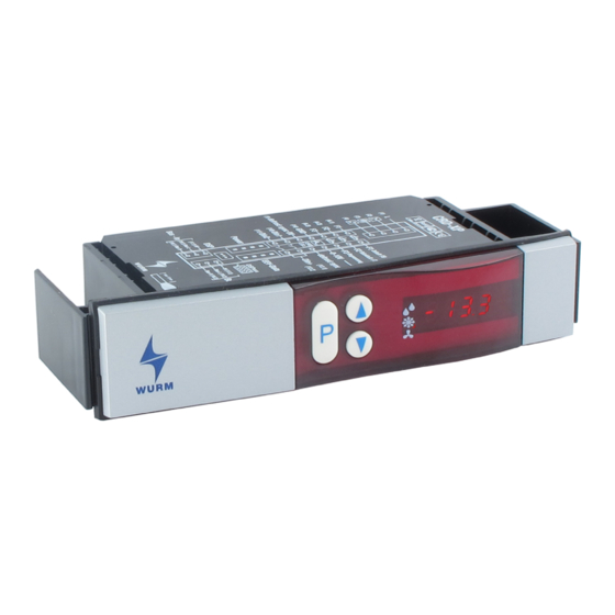
Front view
Features
CRD-XP_2005-12_EN
for installation in commercial refrigerators or cabinet doors
Suitable for all cold location types
(cold rooms and commercial refrigerators etc.)
Forced air, electric, hot or cold gas defrosting
Synchronised defrost of several cold location controllers
Defrosting over fixed times or cyclical interval
Thermostatic fan control
Run-up, run-down function of the fan controller
Surge guard and runtime monitoring
2. Setpoint and independent day / night changeover
Sharp frost function
3-Point control
High voltage range of mains power supply
High electromagnetic compatibility
Fast installation thanks to innovative and elegant fitted housing
Large data storage for temperature history
Subject to technical changes
Universal cold location controller
CRD-XP
Page 1 of 16
Advertisement
Table of Contents

Related Manuals for WURM CRD-XP


Summary of Contents for WURM CRD-XP
- Page 1 CRD-XP Universal cold location controller for installation in commercial refrigerators or cabinet doors Front view Features Suitable for all cold location types (cold rooms and commercial refrigerators etc.) Forced air, electric, hot or cold gas defrosting Synchronised defrost of several cold location controllers...
-
Page 2: Table Of Contents
Accessories Technical data Software revisions and validity of documentation 1 Connection diagrams Photo showing cables connecting CRD-XP to transformer CRD-XP Connection terminals on CRD-XP The wiring diagram applies to devices of Version 2.0 and higher. Caution: On Version 1.0 and 1.1 devices, the cooling and fan output relays have been designed to act as openers. -
Page 3: Operation
CRD-XP 2 Operation Display 1 Set value adjustment enabled 2 Advanced level P00...P73 Defrost Cool Status LED Value/parameter number Selecting parameters 1. Press the <P> key to display the parameter number. The parameter number will appear in the display for as long as the key is depressed. -
Page 4: Description Of Parameters
CRD-XP Adjusting set values 1. Select the parameter to be adjusted (having previously enabled the advanced level if necessary). 2. Set value adjustment enabled. Press all three keys down simultaneously for 5 seconds. The "Set value adjustment enabled" LED flashes. - Page 5 CRD-XP Advanced level: Control Parameter Plant Min. Max. Description Hysteresis Switching differential, symmetrical around set value P02 Upper set value 10°C -50°C +70°C Input of upper adjustment limit for set value in standard level P02 Lower set value 0°C -50°C +70°C...
- Page 6 CRD-XP Parameter Plant Min. Max. Description Fan runup time 0mins 0mins 10 mins Run-up time of fan prior to cooling command => Chapter 5 Fan behaviour, see sequence diagram Fan rundown time 0mins 0mins 10 mins Rundown time of fan following cooling command => Chapter 5...
- Page 7 CRD-XP Advanced level: Digital inputs Parameter Plant Min. Max. Description Digital 0: direct alarm input 1 Zero current principle, direct alarm on loss of current at the input 1: delayed alarm Zero current principle, delayed alarm on loss of current at the input...
-
Page 8: Control
CRD-XP Advanced level: Temperature register Parameter Plant Min. Max. Description 15mins 1min 15mins Register cycle 1min grid, register depth approx. 0.5 days Do not use for continuous operation! 5min time slot pattern, memory depth approx. 2.5 days 10: 10min time slot pattern, memory depth approx. 5 days 15: 15min time slot pattern, memory depth approx. - Page 9 CRD-XP No active temperature control When the controller is used as a pure defrosting slave, the control can be switched to inactive. In this operation mode, dashes represent the regulating actual value in the display. The control probe F1 is not monitored.
-
Page 10: Fan Control
CRD-XP 5 Fan control – Cooling operation and defrosting The parameters P28 and P31 can influence ventilator behaviour. P28 is used to set controls in normal operation, P31 during defrosting. Continuous operation (P28 = 0) If parameter P31 is set to "1", the ventilator is triggered without interruption. At position "0", the ventilator is switched off during defrosting. -
Page 11: Defrosting
CRD-XP 6 Defrosting Display during active defrost During a defrost, the text "dEFr" (defrost) is shown in place of the temperature value in the standard level. The text remains in the display in cold locations with set values of > -15°C to 20 minutes and in cold locations with set values of <... - Page 12 CRD-XP To prevent other devices triggering their own time-controlled defrost, the second device should be programmed as the SLAVE via parameter P17 ("OFF"). On the other hand, additional times are possible through the operation as additional master. On completion of the individual defrost operations triggered by limit probe or time, all synchronised devices wait until all thermometers have received their synchronous signal from the bus before starting cooling.
-
Page 13: Error Messages
CRD-XP 7 Error messages In the event of malfunction, the display flashes with the error code. Depiction of the error code is suppressed in the advanced level (point in lower right flashes). Display Cause of malfunction Monitoring function and emergency program... -
Page 14: Installation
CRD-XP 9 Installation 150 x 32 Installation dimensions for CRD-XP cold location controller Installation dimensions for transformer TR9-9-4 (WZU001) Page 14 of 16 Subject to technical changes CRD-XP_2005-12_EN... -
Page 15: Accessories
CRD-XP 10 Accessories CRD-XP Cooler controller TR9-9-4 (WZU001) Transformer ZCB-C/TR-0.6 Connection cable 0.6m CRD-XP to TR9-9-4 ZCB-C/TR-2.6 (WZU112,VBK9) Connection cable 2.0m CRD-XP to TR9-9-4 TRK277/7 plus Temperature probe 7m connection cable 11 Technical data CRD-XP cold location controller Supply voltage... -
Page 16: Software Revisions And Validity Of Documentation
CRD-XP 12 Software revisions and validity of documentation Software version Functional enhancement Page V1.1 11-2002 Documentation basis First delivered software version V2.0 03-2003 New hardware; all relay contacts are designed as closer contacts V2.1 10-2003 Temperature range expanded to +70°C...
Need help?
Do you have a question about the CRD-XP and is the answer not in the manual?
Questions and answers