
Related Manuals for RKC INSTRUMENT CB103


Summary of Contents for RKC INSTRUMENT CB103
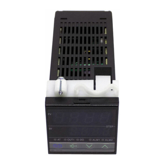
- Page 1 Digital Controller CB103/CB403 CB903 Initial Setting Manual IMCB12-E2 RKC INSTRUMENT INC. ®...
- Page 2 Thank you for purchasing the RKC product. Before operating this instrument, please carefully read this manual and fully understand its contents. And always keep it around you to make it available easily anytime. SYMBOL : If there are possible dangers such as electric shock, fire (burns), etc. which may WARNING result in operator's loss of life or injury, precautions to avoid such dangers are described.
- Page 3 CAUTION This is a Class A instrument. In a domestic environment this instrument may cause radio interference, in which case the user is required to take adequate measures. This instrument is protected from electric shock by reinforced insulation. So please arrange reinforced insulation to the wire for input signal against the wires for instrument power supply, source of power and loads as far as possible.
-
Page 4: Table Of Contents
CONTENTS Page 1. TRANSFER TO MODE............1 1.1 Transfer to Initialization Mode.................1 1.2 End of Initialization Mode................3 2. SETTING ................4 2.1 Display Flowcharts Initialization Mode ............4 2.2 Procedure for Setting Each Parameter ............5 2.3 List of Parameter in Initialization Code (Cod=0) ..........7 2.4 List of Parameter in Initialization Code (Cod=1) ...........15 2.5 List of Parameter in Initialization Code (Cod=2) ...........23 i - 3... -
Page 5: Transfer To Mode
2. Press the SET key for two seconds with the instrument set to PV/SV display mode to change the instrument to parameter setting mode. For details on parameter setting mode, see the instruction manual for CB103/CB403/ CB903 (IMCB11-E ). 3. Press the SET key to change to the set data lock function display (LCK). - Page 6 1. TRANSFER TO MODE 6. Press the SET key to change to the next parameter. Thus, the data in initialization mode is unlocked. STEP OUT1 ALM1 ALM2 CT1 input value display The parameter to be displayed varies depending on the specification. 7.
-
Page 7: End Of Initialization Mode
1. TRANSFER TO MODE 1.2 End of Initialization Mode If the setting is changed, always check all of the set values (SV setting mode, parameter setting mode). section in each picture is dimly lit. 1. Transfer to Initialize code selection after each parameter is set. 2. -
Page 8: Setting
2. SETTING 2.1 Display Flowcharts in Initialization Mode If the instrument is changed to initialization mode, the symbol (Cod) for selecting the initialize code is displayed first. Initializing items are classified into 3 initialize code groups in initialization mode. There are parameters which are not displayed depending on the specification. Press the SET key for two seconds. -
Page 9: Procedure For Setting Each Parameter
2. SETTING 2.2 Procedure for Setting Each Parameter [Example of changing the setting] When the display unit shows SL1 (Input type selection) in initialize code 0, the following procedure is for changing the input type from K to J. section in each picture is dimly lit. 1. - Page 10 2. SETTING 3. Press the UP key to enter 1 in the units digit of the set value (SV) display unit. Set value Input type STEP OUT1 ALM1 ALM2 Input type selection 4. Press the SET key to change to the next parameter. Thus, the set value is registered. STEP OUT1 ALM1...
-
Page 11: List Of Parameter In Initialization Code (Cod=0)
2. SETTING 2.3 List of Parameters in Initialize Code 0 (Cod = 0) (1) SL1 (Input type selection) Conduct the setting so that it matches the instrument specification (input type). If the setting is changed, always check all of the set values (SV setting mode, parameter setting mode). - Page 12 2. SETTING (3) SL3 (Heater break alarm [HBA], control loop break alarm [LBA], special specification, or control loop break alarm [LBA] output selection ) Cannot be used the heater break alarm (HBA) for the following instruments. • Instrument without the second alarm (ALM2) output. •...
- Page 13 2. SETTING (4) SL4 (First alarm [ALM1] type selection, hold action selection) The following instrument is set to 0000. • Instrument without the first alarm (ALM1) output. • Instrument of the SV alarm or control loop break alarm (LBA) is used as the first alarm (ALM1).
- Page 14 2. SETTING (6) SL6 (Direct/reverse action selection, control output type selection) Conduct setting so as to meet the instrument specification. An incorrect setting may cause a malfunction. The tens and thousands digits are not used. As malfunction may result, do not change these digits.
- Page 15 2. SETTING (8) SL8 (Special specification selection 2) Any digits other than the tens digit are not used. As malfunction may result, do not change any of other digits. Factory set value varies depending on the instrument specification. Set value Description Z-185 specification not provided Special specification selection...
- Page 16 2. SETTING (10) SL10 (Option selection) The tens and hundreds digits are not used. As malfunction may result, do not change these digits. Factory set value varies depending on the instrument specification. Set value Description RUN/STOP function not provided RUN/STOP function selection RUN/STOP function provided Fixed Self-tuning not provided...
- Page 17 2. SETTING (12) SL12 (Auxiliary output selection) The auxiliary output can not be used following instruments. • Instrument of the control output type is Trigger output for triac driving. The hundreds digits is not used. As malfunction may result, do not change this digit. Factory set value varies depending on the instrument specification.
- Page 18 2. SETTING (14) SL14 (Third alarm [ALM3] special specification selection) The following instrument is set to 0000. • Instrument of the third alarm (ALM3) are not selected in SL12 (Auxiliary output selection). The tens and thousands digits are not used. As malfunction may result, do not change these digit.
-
Page 19: List Of Parameter In Initialization Code (Cod=1)
2. SETTING 2.4 List of Parameters in Initialize Code 1 (Cod = 1) (1) SLH (Setting limiter [high limit]) Set the limiter by referring to Input range table (P.17). Setting method Press the <R/S key to move the digit, then enter the high limit of the set value (SV) by pressing the UP or DOWN key. - Page 20 2. SETTING (2) SLL (Setting limiter [low limit]) Set the limiter by referring to Input range table (P.17). Setting method Press the <R/S key to move the digit, then enter the high limit of the set value (SV) by pressing the UP or DOWN key.
- Page 21 2. SETTING Input range table Thermocouple input (TC) Type Input range Type Input range 0 to 200 °C 400 to 1800 °C 0 to 400 °C 0 to 1820 °C 0 to 600 °C 800 to 3200 °F 0 to 800 °C 0 to 3308 °F 0 to 1000 °C 0 to 800 °C...
- Page 22 2. SETTING Type Input range 0 to 400 °C 0 to 800 °C 0 to 800 °F 0 to 1600 °F *1 0 to 399 °C/0 to 799 °F: Accuracy is not guaranteed. *2 -199.9 to -100.0 °C/-199.9 to -158.0 °F: Accuracy is not guaranteed. RTD input Type Input range...
- Page 23 2. SETTING Voltage input Type Input range 0 to 5 V DC 0.0 to 100.0 % 1 to 5 V DC Current input Type Input range 0 to 20 mA DC 0.0 to 100.0 % 4 to 20 mA DC For the current input specification, a resistor of 250 Ω...
- Page 24 2. SETTING (3) PGdP (Decimal point position setting) The decimal point position setting is displayed only for voltage or current input. Any digits other than the units digit are not used. As malfunction may result, do not change any of these digits. Factory set value: 0001 Set value Description...
- Page 25 2. SETTING (6) AH2 (Second alarm [ALM2] differential gap setting) Not displayed when there is no second alarm (ALM2). [Setting range] 0 to 100 °C [°F] or 0.0 to 100.0 °C [°F] TC and RTD inputs : Voltage and current inputs : 0.0 to 10.0 % of span [Factory set value] 2 °C [°F] or 2.0 °C [°F] TC and RTD inputs :...
- Page 26 2. SETTING (9) dF (Digital filter setting) Setting range : 0 to 100 sec (If 0 is set, the PV digital filter is turned off.) Factory set value : 1 (10) STTM (Time factor assumed to be safe) *Displayed when the self-tuning is provided. This is the factor to adjust the reference time of establishing the stabilized state of a measured value.
-
Page 27: List Of Parameter In Initialization Code (Cod=2)
2. SETTING 2.5 List of Parameters in Initialize Code 2 (Cod = 2) Parameters in initialize code 2 are only displayed. (1) TCJ (Holding peak ambient temperature) The maximum ambient temperature on the rear terminal board of the instrument is stored and displayed on the set value (SV) display unit. - Page 28 RKC INSTRUMENT INC. HEADQUARTERS: 16-6, KUGAHARA 5-CHOME, OHTA-KU TOKYO 146-8515 JAPAN PHONE: 03-3751-9799 (+81 3 3751 9799) E-mail: info@rkcinst.co.jp FAX: 03-3751-8585 (+81 3 3751 8585) IMCB12-E2 FEB.2000...
Need help?
Do you have a question about the CB103 and is the answer not in the manual?
Questions and answers