Table of Contents
Advertisement
Quick Links
R3399X-2C / R3399XH-2C/ R3399XL-2C Series
User's Manual
P/N: G03-R3399-F
Revision: 3.0
Release date: December 8, 2022
Trademark:
* Specifications and Information contained in this documentation are furnished for information use only, and are
subject to change at any time without notice, and should not be construed as a commitment by manufacturer.
Advertisement
Table of Contents

Related Manuals for JETWAY R3399X-2C Series


Summary of Contents for JETWAY R3399X-2C Series
- Page 1 R3399X-2C / R3399XH-2C/ R3399XL-2C Series User’s Manual P/N: G03-R3399-F Revision: 3.0 Release date: December 8, 2022 Trademark: * Specifications and Information contained in this documentation are furnished for information use only, and are subject to change at any time without notice, and should not be construed as a commitment by manufacturer.
- Page 2 Environmental Protection Announcement Do not dispose this electronic device into the trash while discarding. To minimize pollution and ensure environment protection of mother earth, please recycle.
-
Page 3: Table Of Contents
TABLE OF CONTENT ENVIRONMENTAL SAFETY INSTRUCTION................... iii USER’S NOTICE............................ iv MANUAL REVISION INFORMATION....................iv ITEM CHECKLIST..........................iv CHAPTER 1 INTRODUCTION OF THE MOTHERBOARD FEATURE OF MOTHERBOARD..................1 SPECIFICATION........................2 PRODUCT DIAGRAM......................3 CHAPTER 2 HARDWARE INSTALLATION REAR I/O CONNECTORS....................8 INTERNAL CONNECTORS, HEADERS AND JUMPERS..........9... -
Page 4: Environmental Safety Instruction
Environmental Safety Instruction Avoid the dusty, humidity and temperature extremes. Do not place the product in any area where it may become wet. 0 to 40 centigrade is the suitable temperature. (The temperature comes from the request of the chassis and thermal solution) ... -
Page 5: User's Notice
USER’S NOTICE COPYRIGHT OF THIS MANUAL BELONGS TO THE MANUFACTURER. NO PART OF THIS MANUAL, INCLUDING THE PRODUCTS AND SOFTWARE DESCRIBED IN IT MAY BE REPRODUCED, TRANSMITTED OR TRANSLATED INTO ANY LANGUAGE IN ANY FORM OR BY ANY MEANS WITHOUT WRITTEN PERMISSION OF THE MANUFACTURER. -
Page 6: Chapter 1 Introduction Of The Motherboard
Chapter 1 Introduction of the Motherboard 1-1 Feature of Motherboard Rockchip RK3399 6-core: Rockchip ARM Cortex A72(Dual Core, 1.8Ghz) + ® ® Cortex A53(Quad Core, 1.4GHz) Onboard 2GB/1333MHz DDR3L DRAM Onboard 16GB Flash ROM (Max 64GB) Support WIFI and BlueTooth ... -
Page 7: Specification
1-2 Specification Spec Description From Factor 102 * 146mm Rockchip RK3399 6-core: Rockchip ARM Cortex A72(Dual Core 1.8 ® ® GHz) +Cortex A53(Quad Core 1.4GHz) Rockchip RK808-D PMU ® Memory Onboard 2GB/1333MHz DDR3L DRAM Storage Onboard 16GB EMMC Flash ROM (Max. 64GB) ... -
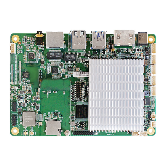
Page 8: Product Diagram
1* EDP_VCC Jumper 1* LVDS Header &1* Inverter Connector(R3399X-2C/R3399XH-2C) 1* LVDS_BKLT Jumper(R3399X-2C/R3399XH-2C) 1* LVDS_POWER Jumper(R3399X-2C/R3399XH-2C) 1-3 Product Diagram Rear IO Panel Diagram R3399X-2C: *LAN2 HDMI-In RJ-45 Port Port (10/100Mbps) USB 3.0 Port Line-Out & MIC 12V DC-in HDMI-Out RJ-45 Port Combo Jack... - Page 9 R3399XL-2C: *USB 2.0 Port USB 3.0 Port Line-Out & MIC HDMI-Out 12V DC-in Combo Jack RJ-45 Port Port Power Jack (10/100/1000Mbps) *Note: This manual serves as common manual for R3399X-2C, R3399XH-2C and R3399XL-2C models, which share most of the specifications. Differences of these models are listed as below: Optional Item R3399X-2C R3399XH-2C...
- Page 10 Motherboard Internal Diagram UART3: UART1: Top View: RS232/UART TTL UART TTL/RS485 (Default: RS232) (Default: UART TTL) UART4: DEBUG: BAT: UART TTL/RS232 Debug Battery Connector (Default: UART TTL) UART5: FAN: UART TTL CPUFAN JP8: Power Switch & Recover RESETKEY: Reset *FP_USB20: EDP: GPIO_VCC USB 2.0 Port...
- Page 11 Bottom View: SIM1 (Bottom): SIM Card Socket Rear Connectors: Name DCIN 12V DC–In Power Jack Top: HDMI-In Port HDMI1(R3399X-2C) Bottom: HDMI-Out Port HDMI1(R3399XH-2C/ R3399XL-2C) HDMI-Out Port Top: USB 3.0/OTG Co-Lay Port USB1 Bottom: USB 3.0 Port USB20_1(R3399XL-2C) USB 2.0 Port x2 LAN2(R3399X-2C/ R3399XH-2C) 10/100 Mbps RJ-45 LAN Port...
- Page 12 10/100/1000 Mbps RJ-45 LAN Port Audio Line-out & MIC Combo Jack J9100 Micro-SD (TF) Card Socket (Bottom side) SIM Card Socket SIM1 Internal Connector, Headers & Jumpers: Name Description Power Switch/Recovery Connector 3-pin Block RESETKEY Reset Connector 2-pin Block CPUFAN Connector 2-pin Block UART1 UART TTL/ RS485 Connector...
-
Page 13: Chapter 2 Hardware Installation
Chapter 2 Hardware Installation 2-1 Rear I/O Connectors *For Rear IO please refer to Page-3/4. Icon Name Function For user to connect compatible power adapter to 12V DC-in DCIN provide power supply for the system. Power Jack Top: To connect display input device that support HDMI1 Top: HDMI-IN HDMI specification. -
Page 14: Internal Connectors, Headers And Jumpers
For user to insert compatible micro-SD (TF) card Macro-SD (TF) J9100 (Top) into the socket. Card Socket SIM1 SIM Card Socket For user to install compatible SIM card. (Bottom) 2-2 Internal Connectors, Headers & Jumpers JP8 (3-pin): Power Switch & Recovery Connector PWRON Recover Pin1... - Page 15 RESETKEY (2-pin): Reset Connector RESETKEY Pin1 RESET FAN (2-pin): CPUFAN Connector Pin1...
- Page 16 BAT (2-pin): COMS Battery Connector Pin1 UART1 (4-pin): UART TTL/ RS485 Connector UART1 Pin1 Pin1 UART1=TTL UART1=RS485 (Default) (Optional)
- Page 17 DEBUG (4-pin): Debug Connector DEBUG Pin1 UART3 (4-pin): RS232/UART TTL Connector UART3 Pin1 UART3=RS232 (Default); UART3=TTL (Optional).
- Page 18 UART4 (4-pin): UART TTL/RS232 Connector UART4 Pin1 UART4=TTL (Default); UART4=RS2332 (Optional). UART5 (4-pin): UART TTL Connector UART5 Pin1 UART5=TTL.
- Page 19 FP_USB2/FP_USB3 (9-pin): USB 2.0 Header Pin1 FP_USB2 FP_USB3 *FP_USB20 (9-pin): USB 2.0 Header *FP_USB20 *Note: FP_USB20 is optional to R3399X-2C/ R3399XH-2C series only.
- Page 20 SPK (4-pin): 3W Speaker Connector Pin1 GPIO (16-pin): 8-bit GPIO & I2C Combo Header Block Pin1 GPIO *Note: Pin 15 & 16 short = EMMC_UPDATE (If EMMC_CLKO=0V after power-on reset, then system will enter into Maskrom mode).
- Page 21 GPIO_VCC (3-pin): GPIO_VCC Select Jumper GPIO_VCC...
- Page 22 *CSI (15-pin): MIPI CSI Connector Pin Define VCC3V3 I2C2_SDA I2C2_SCL MCLK GPIO2_B4 CLKP CLKN *CSI Pin15 Pin1 *Note: MIPI CSI is optional to R3399X-2C/ R3399XH-2C series only.
- Page 23 EDP (20-pin): EDP Header Pin1 Pin2 Pin Define Pin No. Pin No. Pin Define BKLT_12V EDP_TX0N EDP_TX0P EDP_TX1N EDP_TX1P EDP_TX2N EDP_TX2P EDP_TX3N EDP_TX3P EDP_AUXN EDP_AUXP LED_EN BKLT_3.3 BKLT_5V...
- Page 24 EDP_VCC (4-pin): EDP LCD Power VCC Select Jumper EDP_VCC EDP LCD Power VCC → 2 4 6 2 4 6 EDP_VCC 1 3 5 1 3 5 2-4 Closed=3.3V; 3-4 Closed=5V; 4-6 Closed=12V. *INVERTER (6-pin): LVDS Inverter Connector Pin1 *INVERTER...
- Page 25 *LVDS (30-pin): 24-bit dual channel LVDS Header Pin1 Pin2 *LVDS Pin Define Pin No. Pin No. Pin Define R2AN R2AP R2BN 9 10 R2BP R2CN 11 12 R2CP 13 14 R2CLKN 15 16 R2CLKP R2DN 17 18 R2DP R1AN 19 20 R1AP R1BN 21 22...
- Page 26 *LVDS_BKLT (4-pin): LVDS Backlight VCC Select Jumper LVDS_BKLT Inverter Backlignt VCC → 5 3 1 5 3 1 6 4 2 6 4 2 2-4 Closed=3.3V; 3-4 Closed=5V; 4-6 Closed=12V. *LVDS_BKLT *LVDS_POWER (6-pin): LVDS LCD Power VCC Select Jumper Pin1 Pin1 1-2 Closed: VCC = 12V;...
Need help?
Do you have a question about the R3399X-2C Series and is the answer not in the manual?
Questions and answers