
Related Manuals for Eaton XNE-1SWIRE


Summary of Contents for Eaton XNE-1SWIRE
- Page 1 09/2011 MN05002016Z-EN User Manual XI/ON replaces M001734-03, 10/2008 XNE-1SWIRE Technology Module...
- Page 2 All rights reserved, also for the translation. None of this document may be reproduced or processed, duplicated or distributed by electronic systems in any form (print, photocopy, microfilm or any other process) without the written permission of Eaton Automa- tion AG, St. Gallen.
- Page 3 ▶ Wherever faults in the automation system may cause damage to persons or property, external measures must be implemented to ensure a safe operating state in the event of a fault or malfunction (for example, by means of separate limit switches, mechanical in- terlocks etc.). XI/ON: XNE-1SWIRE 09/2011 MN05002016Z-EN www.eaton.com...
- Page 4 (e.g. with regard to cable cross sections, fuses, PE). ▶ All work relating to transport, installation, commissioning and maintenance must only be carried out by qualified personnel. (IEC/HD 60364 (DIN VDE 0100) and national work safety regula- tions). XI/ON: XNE-1SWIRE 09/2011 MN05002016Z-EN www.eaton.com...
-
Page 5: Table Of Contents
Additional documentation ................ 9 Product description ................11 Features ....................11 Function parameterization..............12 2.2.1 Scan physical structure and store in the XNE-1SWIRE......12 2.2.2 Activate and deactivate PLC configuration check ........13 2.2.3 System behavior with positive configuration checks......13 2.2.4... - Page 6 Special system behavior with the «Moeller Conformance» function ..51 System behavior with the configuration checks («Moeller Conformance») ..............52 Configuration of the XNE-1SWIRE with MXpro ....... 53 Configuration of the XN-PLC-CANopen station........54 Configuration of the XNE-1SWIRE as local module on the XN-PLC-CANopen ...............
-
Page 7: General
Indicates a potentially hazardous situation which, if not avoided, could result in slight injury or material damage. Indicates important information not related to safety. The danger symbol used and the text indicate the actual danger and the related preventative measures. XI/ON: XNE-1SWIRE 09/2011 MN05002016Z-EN www.eaton.com... -
Page 8: Purpose Of This User Manual
▶ Always work with the complete original User Manual. 1.2.1 Comments about the User Manual Please send any comments, recommendations or suggestions relating to this User Manual to: automation@eaton.com XI/ON: XNE-1SWIRE 09/2011 MN05002016Z-EN www.eaton.com... -
Page 9: Additional Documentation
The following documents on the subject of SmartWire are available from www.moeller.net: [7] AWB1210+1251-1591 Connection system SmartWire Modules (Power module, I/O module, module for DILM) [8] AWB2528-1589 Connection system SmartWire-Easy223-SWIRE (easy Gateway, CAN-Open Gateway) [9] AWB1251-1590 Connection system SmartWire-SWIRE-GW-DP (PROFIBUS-DP Gateway) XI/ON: XNE-1SWIRE 09/2011 MN05002016Z-EN www.eaton.com... - Page 10 1 General 1.3 Additional documentation XI/ON: XNE-1SWIRE 09/2011 MN05002016Z-EN www.eaton.com...
-
Page 11: Product Description
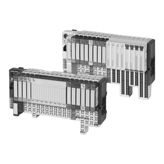
Fig. 1 XNE-SWIRE module in a XI/ON CANopen station with 4 SWIRE slaves Features The XNE-1SWIRE makes it possible to operate an SWIRE bus with up to 16 SWIRE slaves. A 6-core cable is used here for power and data transfer. A XI/ON station can contain max. -
Page 12: Function Parameterization
• The configuration is stored in the XNE-1SWIRE. Manual To store the physical structure of the SWIRE bus in the XNE-1SWIRE, the CFG SWIRE configuration button of the XNE-1SWIRE must be pressed manually (only functions if the SW LED (default setting) is flashing). -
Page 13: Activate And Deactivate Plc Configuration Check
2.2.2 Activate and deactivate PLC configuration check During the PLC configuration check, the configuration stored in the XNE-1SWIRE is compared with the SET configuration stored in the PLC. The complete device ID must match. If the two configurations match completely, the entire SWIRE bus is ready for data exchange (RDY LED lit). -
Page 14: System Behavior With Negative Configuration Checks And Slave Failure
The operation is aborted if the «Moeller Conformance» function is activated. The SWIRE bus only starts operation: • After the physical structure was stored in the XNE-1SWIRE and a match was determined: • Manually, by pressing the CFG button (only functions if the SW LED is flashing). - Page 15 • If the PLC configuration check is activated and the configuration check is set to Bus-oriented, data exchange is only restarted if the configuration stored in the XNE-1SWIRE matches the SET configuration stored in the PLC. The operation for the entire SWIRE bus is aborted if they do not match completely.
- Page 16 (default setting) If the physical structure of the SWIRE bus does not match the configuration stored in the XNE-1SWIRE on power up (SW LED flashing), the physical structure is compared continuously with the configuration stored in the XNE-1SWIRE. The SWIRE bus starts operation as soon as the matching configurations are detected: •...
- Page 17 If the physical structure of the SWIRE bus does not match the configuration stored in the XNE-1SWIRE on power up (SW LED flashing), the physical structure is compared continuously with the configuration stored in the XNE-1SWIRE. The SWIRE bus starts operation as soon as the matching configurations are detected: •...
-
Page 18: Other Parameters
If the PLC configuration check is activated, data exchange is only started if the configuration stored in the XNE-1SWIRE fully matches the SET configuration stored in the PLC. If the two configurations do not match completely (RDY LED flashing), the operation is aborted for the entire SWIRE bus (RDY LED flashing). -
Page 19: Technical Features
2 Product description 2.4 Technical features Technical features Fig. 2 XNE-1SWIRE module linked to a GWBR-CANopen gateway 2.4.1 Block diagram module bus interface module bus slave SWIRE master SWIRE driver SWIRE interface Fig. 3 Block diagram for XNE-1SWIRE XI/ON: XNE-1SWIRE 09/2011 MN05002016Z-EN www.eaton.com... -
Page 20: Technical Data
Power supply of contactors U (range) 24 V DC (18 to 30 V DC) Power supply current of contactors SWIRE connection Number of SWIRE buses Number of XNE-1SWIRE modules per max. 3 XI/ON station Number of SWIRE slaves per bus max. 16... -
Page 21: Indication Elements
The voltage U is within the permissible range and the module bus voltage is present. The voltage U is faulty. (indication of the relay Green The voltage U is in the permissible supply of the bus) range. XI/ON: XNE-1SWIRE 09/2011 MN05002016Z-EN www.eaton.com... -
Page 22: Approved Swire Slaves
2 Product description 2.7 Approved SWIRE slaves Tab. 2 LED indication elements Approved SWIRE slaves The following slaves on the SWIRE bus are currently approved for the XNE-1SWIRE: Device Manufacturer 0x20 SWIRE-DIL Moeller 0x21 SWIRE-4DI-2DO-R Moeller 0x01 PH9285.91 Dold 0x02 PH9285.91/001... -
Page 23: Wiring Diagram And Pin Assignment
The following diagram is an example of the connected SWIRE power supply with a disconnection function (emergency-off) for the coil supply of the SWIRE relays. Fig. 4 Connection of the operating voltage for the XNE-1SWIRE with disconnectable coil power supply of the SWIRE relays The following diagram is a connection example for the SWIRE power supply. - Page 24 PIN 3 and PIN 4 are bridged inter- nally! GND frame potential relay power supply PIN 4 and PIN 6 are bridged inter- nally! relay power supply Tab. 4 Pin assignment of the connection terminals XI/ON: XNE-1SWIRE 09/2011 MN05002016Z-EN www.eaton.com...
-
Page 25: Integration Of The Module In Profibus-Dp
The field input data is transferred from the connected SWIRE bus to the XNE- 1SWIRE. The process input data is the data that is transferred by the XNE-1SWIRE module via a gateway to the PLC. The transfer is carried out in 8-byte format. 4 bits are reserved for each SWIRE slave. - Page 26 The information is provided as status information in the PLC for the user. ON LINE ON LINE Status of slave x: Everything o.k. OFF LINE OFF LINE Status of slave x: One/several diagnostics messages present. Tab. 7 Meaning of data bits XI/ON: XNE-1SWIRE 09/2011 MN05002016Z-EN www.eaton.com...
-
Page 27: Process Output
3.1.2 Process output Field output data is output from an XNE-1SWIRE to a field device. The process output data is the data that is transferred by the PLC via a gateway and the XNE- 1SWIRE to the SWIRE slaves. The transfer is carried out in 8-byte format. 4 bits are reserved for each SWIRE slave. - Page 28 Tab. 12 Process output data of approved SWIRE slaves (except SWIRE-DIL) If a slave does not support the number of 4 output bits, the outputs are assigned to the process output data in ascending order, likewise starting from the least signifi- cant bit. XI/ON: XNE-1SWIRE 09/2011 MN05002016Z-EN www.eaton.com...
-
Page 29: Diagnostics
When “Device-related Diagnostics” is selected, an abbreviated diagnostics message is generated that simply shows the gateway diagnostics (device-related diagnostics). The diagnostics bytes of all station modules are attached that support diagnostics. This should be interpreted as follows for the XNE-1SWIRE modules: Bit 7 Bit 6 Bit 5... - Page 30 (SW LED flashing). PLC SLAVE This bit indicates an error if the configuration stored in the XNE-1SWIRE does not match the SET configura- tion stored in the PLC. No error present. The SWIRE bus is ready for data exchange.
- Page 31 SWIRE slave. The PLC configuration check was posi- tive (the configuration stored in the XNE-1SWIRE matches the SET config- uration stored in the PLC) or the diag- nostics function is deactivated via the parameter setting.
- Page 32 Sx has tripped. The PKZ of the slave has not tripped or diagnostics function has been deacti- vated via the parameter setting. Tripped The PKZ of the slave has tripped. Tab. 14 Meaning of diagnostics data bits XI/ON: XNE-1SWIRE 09/2011 MN05002016Z-EN www.eaton.com...
-
Page 33: Parameter
S11 SC S10 SC DIAG DIAG DIAG DIAG DIAG DIAG DIAG DIAG Byte 7 reserved Byte 8 reserved Byte 9 Type designation slave 1 - 16 - 24 Tab. 15 Data structure of the parameters XI/ON: XNE-1SWIRE 09/2011 MN05002016Z-EN www.eaton.com... - Page 34 Automatic SWIRE configuration If the physical structure of the SWIRE bus does not match the configuration stored in the XNE-1SWIRE on power up (SW LED flashing), the physical struc- ture of the SWIRE bus must be stored in the XNE-1SWIRE.
- Page 35 Sx. As soon as a slave on the bus does not match the set configuration and therefore cannot be started, this is indicated as an individual error depending on the parameter setting. Active Single diagnostics is activated. Inactive Single diagnostics is not activated. XI/ON: XNE-1SWIRE 09/2011 MN05002016Z-EN www.eaton.com...
- Page 36 TYPE setting for the SWIRE slave at position x on the SWIRE bus. slave x 0x20 SWIRE-DIL (Moeller) 0x21 SWIRE-4DI-2DO-R (Moeller) 0x01 PH9285.91 (Dold) 0x02 PH9285.91/001 (Dold) 0x03 PH9285.91/002 (Dold) 0xFF Basic setting (no slave) Tab. 16 Meaning of the parameter bits XI/ON: XNE-1SWIRE 09/2011 MN05002016Z-EN www.eaton.com...
-
Page 37: Integration Of The Module In Devicenet
# OF INSTANCES USINT Contains the number of the object instances created on this class level. MAX CLASS ATTR USINT Contains the number of the last implemented class attribute. Tab. 17 Class instance XI/ON: XNE-1SWIRE 09/2011 MN05002016Z-EN www.eaton.com... - Page 38 BYTE: Signal byte sequence MODULE REGISTERED ENUM Contains the index number listed in all module lists. INDEX USINT NUMBER OF SUPPORTED USINT Shows the number of input channels supported by INPUT CHANNELS this module instance. XI/ON: XNE-1SWIRE 09/2011 MN05002016Z-EN www.eaton.com...
- Page 39 DIAG_PKZ_ERROR. Slave 1 belongs to bit 0, slave 2 to bit 1 etc. 0: No PKZ has tripped or diagnostics function has been deactivated via the parameter setting. 1: At least one PKZ has tripped. XI/ON: XNE-1SWIRE 09/2011 MN05002016Z-EN www.eaton.com...
- Page 40 Bit 1 - Automatic SWIRE configuration 0: Manual SWIRE configuration: To store the physical structure of the SWIRE bus in the XNE-1SWIRE, the CFG button of the XNE- 1SWIRE must be pressed manually (only functions if the SW LED is flashing).
- Page 41 0: Slave diagnostics message from Byte 1 / Bit 7 is accepted in the feedback interface as Bit4. 1: Slave diagnostics message from Byte 1 / Bit 7 is accepted in the feedback interface as Bit 4. XI/ON: XNE-1SWIRE 09/2011 MN05002016Z-EN www.eaton.com...
- Page 42 Description dec. (hex.) PARAM_SWIRE_TYPE_IDE BYTE Bit 0 to bit 3 - Variant ID ) to No slave SLAVE_1 TO SWIRE-DIL (Moeller) PARAM_SWIRE_TYPE_IDE SWIRE-4DI-2DO-R (Moeller) PH9285.91 (Dold) SLAVE_1 PH9285.91/001 (Dold) PH9285.91/002 (Dold) Tab. 18 Object Instance XI/ON: XNE-1SWIRE 09/2011 MN05002016Z-EN www.eaton.com...
-
Page 43: Integration Of The Module In Canopen
PDO mapping must be carried out by the user. The structure of the process input data of the XNE-1SWIRE module is described in Chapter 3.1.1 Process input, Page 25. This description is followed by a table with explanations on the meaning of the individual bits. -
Page 44: Representation Of Diagnostics Data
5.3 Representation of diagnostics data Representation of diagnostics data The 8 bytes of diagnostics data for the XNE-1SWIRE module are represented by the manufacturer specific objects of the CANopen gateway. The following manufacturer specific objects for representing the diagnostics data are used: •... -
Page 45: Object 3044 Hex - Xbi Diag Dword
XI/ON module bus. The sub-index 1 to 74 corresponds to the module number of the XI/ON module. Property Object 3045 INDEX 3045 Name XBI Diag Dword2 Object Code ARRAY Data type Unsigned32 Access Default value XI/ON PDO mapping Tab. 21 Object 3045 - Description XI/ON: XNE-1SWIRE 09/2011 MN05002016Z-EN www.eaton.com... -
Page 46: Representation Of Parameter Data
5.4 Representation of parameter data Representation of parameter data The 24 bytes of parameter data for the XNE-1SWIRE module are represented by the manufacturer specific objects of the CANopen gateway. The following manufacturer specific objects for representing the parameter data are used: •... -
Page 47: Object 3060 Hex - Xbi Param Byte
XI/ON module bus. The sub-index 1 to 74 corresponds to the module number of the XI/ON module. Property Object 3062 INDEX 3062 Name XBI Param Word Object Code ARRAY Data type Unsigned16 Access Default value XI/ON PDO mapping Tab. 24 Object 3062 - Description XI/ON: XNE-1SWIRE 09/2011 MN05002016Z-EN www.eaton.com... -
Page 48: Object 3064 Hex - Xbi Param Dword
XI/ON module bus. The sub-index 1 to 74 corresponds to the module number of the XI/ON module. Property Object 3065 INDEX 3065 Name XBI Param Dword2 Object Code ARRAY Data type Unsigned32 Access Default value XI/ON PDO mapping Tab. 26 Object 3065 - Description XI/ON: XNE-1SWIRE 09/2011 MN05002016Z-EN www.eaton.com... -
Page 49: Object 3066 Hex - Xbi Param Dword3
XI/ON module bus. The sub-index 1 to 74 corresponds to the module number of the XI/ON module. Property Object 3067 INDEX 3067 Name XBI Param Dword4 Object Code ARRAY Data type Unsigned32 Access Default value XI/ON PDO mapping Tab. 28 Object 3067 - Description XI/ON: XNE-1SWIRE 09/2011 MN05002016Z-EN www.eaton.com... -
Page 50: Object 3068 Hex - Xbi Param Dword5
SWIRE modules | 4 | 6 | 5 | 7 Tab. 31 Additional emergencies Bytes 6 and 7 of the Emergency frame contain the result of the bit OR operation of the stated Diag bytes. XI/ON: XNE-1SWIRE 09/2011 MN05002016Z-EN www.eaton.com... -
Page 51: Moeller Swire Conformance Criteria
• Bus-oriented configuration check • Slave-oriented configuration check • To store the physical structure of the SWIRE bus in the XNE-1SWIRE, the CFG button of the XNE-1SWIRE must be pressed manually (only functions if the SW LED is flashing). •... -
Page 52: System Behavior With The Configuration Checks ("Moeller Conformance")
XNE-1SWIRE (SW LED flashing). The SWIRE bus only starts operation: • After the physical structure was stored in the XNE-1SWIRE and a match was determined: • Manually, by pressing CFG button (only functions if the SW LED is flashing). -
Page 53: Configuration Of The Xne-1Swire With Mxpro
6.2 System behavior with the configuration checks («Moeller Conformance») Configuration of the XNE-1SWIRE with MXpro The following configuration example shows how to integrate the XNE-1SWIRE as a local module in the XN-PLC-CANopen station and as a remote module on an XN- GWBR-CANopen. -
Page 54: Configuration Of The Xn-Plc-Canopen Station
7 Configuration of the XNE-1SWIRE with MXpro 7.1 Configuration of the XN-PLC-CANopen station Configuration of the XN-PLC-CANopen station Once the XN-PLC-CANopen has been defined in the project as the target system, it must be configured in the PLC configuration. The local slaves on the XN-PLC- CANopen are selected under XN-PLC-CANopen[SLOT] Inputs/Outputs. - Page 55 CANopen PDOs (process data objects) can contain up to 8 bytes of data. The data volume of the XNE-1SWIRE required the size of a complete send PDO and a complete receive PDO. If other digital modules are present in the station, the data of the XNE-1SWIRE can be assigned to different PDOs as digital data is arranged without any gaps in a PDO according to the physical arrangement in the station.
- Page 56 7 Configuration of the XNE-1SWIRE with MXpro 7.1 Configuration of the XN-PLC-CANopen station Fig. 11 Assigning the COB-ID to the PDO 0x1404 Fig. 12 Assigning the COB-ID to the PDO 0x1804 XI/ON: XNE-1SWIRE 09/2011 MN05002016Z-EN www.eaton.com...
- Page 57 7 Configuration of the XNE-1SWIRE with MXpro 7.1 Configuration of the XN-PLC-CANopen station The CanUser-Master.lib and CANUser_Master.lib must be added to the Library and the variable declaration must be added via Project/Import CanUser.exp and CanUserMaster.exp in order to support the CAN master functionality of the XN-PLC- CANopen.
- Page 58 7 Configuration of the XNE-1SWIRE with MXpro 7.1 Configuration of the XN-PLC-CANopen station The number of data segments must then be increased (max. 12) via Project/Options/Build Options. Fig. 15 Number of data segments XI/ON: XNE-1SWIRE 09/2011 MN05002016Z-EN www.eaton.com...
-
Page 59: Configuration Of The Xne-1Swire As Local Module
In this example the XNE-1SWIRE is set for the following functions: • The physical structure of the SWIRE bus should be stored automatically in the XNE-1SWIRE. This deactivates the function of the CFG button of the XNE- 1SWIRE. • Activate automatic SWIRE configuration. -
Page 60: Configuration Of The Xne-1Swire As A Remote Module
The XNE-1SWIRE on the XN-GWBR-CANopen was fitted as the first I/O module directly behind the gateway. As the process data of the XNE-1SWIRE is included as digital I/O data, 2 or 4-channel digital modules in front of the XNE-1SWIRE would make allocations unclear. - Page 61 • The SWIRE bus does not start operation if the physical structure of the SWIRE bus does not match the configuration stored in the XNE-1SWIRE (SW LED flashing). If the CFG button of the XNE-1SWIRE is then pressed, the physical structure of the SWIRE bus is scanned, each slave is assigned an address and stored in the respective slave and the configuration is stored in the XNE-1SWIRE.
- Page 62 7 Configuration of the XNE-1SWIRE with MXpro 7.3 Configuration of the XNE-1SWIRE as a remote module on the XN-GWBR-CANopen XI/ON: XNE-1SWIRE 09/2011 MN05002016Z-EN www.eaton.com...
Need help?
Do you have a question about the XNE-1SWIRE and is the answer not in the manual?
Questions and answers