
Related Manuals for Pelton & Crane 1500


Summary of Contents for Pelton & Crane 1500
- Page 1 1500 Cart Delivery System Model 1540 Doctor’s Assistant Cart Use & Care Manual Model 1550 Doctor’s Cart...
-
Page 2: Table Of Contents
TABLE OF CONTENTS 1500 CART USE & CARE CONTENTS TABLE OF CONTENTS ......................................2 1500 CART OVERVIEW ......................................3 GENERAL INFORMATION ......................................4 1500 MODEL CONTROL HEAD ....................................5 GENERAL INFORMATION ......................................6 TECHNICAL DESCRIPTION ..................................... 7 FEATURES, CONTROLS AND OPERATIONS ................................. 8 FEATURES, CONTROLS AND OPERATIONS ................................. -
Page 3: 1500 Cart Overview
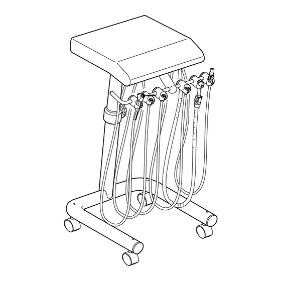
1500 CART OVERVIEW Model 1540 Doctor’s-Assistant Cart Model 1550 Doctor’s Cart 042300 r4... -
Page 4: General Information
GENERAL INFORMATION Product Disposal Definition of Symbols Contact your local authorized dealer for proper disposal of the device to ensure compliance with your local The following symbols may be used throughout environmental regulations. this manual: Interference with Electromedical Devices To guarantee the operational safety of electromedical CAUTION: Failure to carefully follow the described devices, it is recommended that the operation of mobile procedure may result in damage to the equipment. -
Page 5: 1500 Model Control Head
1500 MODEL CONTROL HEAD Coolant Air Routing Flow Valve Water QD Water Vacuum Flow Canister Control Air Flow Control On/Off Air Pressure Gauge Flush Valve Coolant Water Flow Model 1550 Only Vertical Brake Collector 042300 r4... -
Page 6: General Information
GENERAL INFORMATION The pre-installation must be performed according to the requirements in our ‘Pre-installation Instructions’. As manufacturers of electro-medical products we can assume responsibility for safety-related performance of the equipment only if maintenance, repair and modifications are carried out only by us or agencies we have authorized for this purpose, and if components affecting safe operation of the unit that may be needed are replaced with original parts. -
Page 7: Technical Description
TECHNICAL DESCRIPTION Intended Use - Dental Cart & Unit The Models 1540 and 1550 carts feature the Asepsis a junction box. Cart Delivery Units are mounted on a Automatic Control for three handpieces mounted mobile cart. on a mobile cart. In addition to the three handpiece controls, the Model 1540 also comes with Assistant’s Air, water, vacuum, drain and electrical power generally enter the system through the junction box. -
Page 8: Features, Controls And Operations
Control Head Handpiece Activation All of the operating controls are located on the 1500 Models: underside of the control head, where they are better sheltered from airborne contaminants. The Handpiece Autoholders contain actuator valves that allow the operation of whichever... -
Page 9: Features, Controls And Operations
FEATURES, CONTROLS AND OPERATIONS Handpiece Water Coolant Handpiece Air Coolant The water coolant characteristics vary The air coolant flow control will affect all of the significantly from one handpiece to another, so handpiece positions in unison. Since the air individual flow controls are provided. Perform coolant characteristics of most handpieces are the following steps to adjust the water coolant similar, one setting is normally acceptable... -
Page 10: Features, Controls And Operations
FEATURES, CONTROLS AND OPERATIONS The Foot Control (All Models) The unit is equipped with wet-dry, variable speed, disc type foot controls. Foot pressure on any part of the foot control disc controls the flow of air to the active handpiece. A signal relay within the foot control simultaneously activates the air and water coolant. -
Page 11: Features, Controls And Operations
FEATURES, CONTROLS AND OPERATIONS Drive Air Pressure 1. Raise the hinged cover by removing Maximum handpiece speed is controlled by security screws and expose the adjusting the drive air pressure. The adjusting internal components. screws are located inside the control head. There is a separate adjusting screw for each 2. -
Page 12: Operation & Routine Adjustments
OPERATION & ROUTINE ADJUSTMENTS Repositioning the Handpiece Holders The handpiece holders are attached to the holder bar by two socket head setscrews. To reposition a holder, use a 1/8-inch hex key to loosen the setscrews, move the holder to the desired position, then retighten the screws. -
Page 13: Cleaning, Disinfecting & Sterilization
CLEANING, DISINFECTING & STERILIZATION Cleaning Equipment can be cleaned with a solution of mild detergent and warm water. A variety of surface disinfectants are available for use in dental treatment rooms. Some of these can cause discoloration of painted, plated or anodized surfaces with repeated use. -
Page 14: Clean Water System
CLEAN WATER SYSTEM Maintenance The water bottle system is designed to optimize the quality of water being delivered to the handpieces and syringe. The Clean Water System has three functions: CAUTION: Disinfect new water bottle prior to use. The system may be filled with filtered or sterile water for patient use. -
Page 15: Maintenance
MAINTENANCE Care of the Unit Asepsis Automatic Control Control Head and Arm The control head and post can be cleaned with a solution IMPORTANT: Do not use powdered cleansers, of mild detergent and warm water. A variety of surface scouring pads or abrasive scrubbers on any of disinfectants are available for use in dental treatment the painted, plastic or metal surfaces of this den- rooms. -
Page 16: Preventative Manitenance
PREVENTATIVE MANITENANCE Three Months Check air switch levers on handpiece holders. Ensure no build-up has occurred and that levers operate freely. Handpiece Oil Collector: Replace the three 2 x 2 gauzes with clean gauzes in the handpiece oil collector every 90 days or more often is handpieces are oiled frequently. -
Page 17: Assistant's Adjustments
ASSISTANT’S ADJUSTMENTS Changing the Bottle 1. Turn the master toggle switch OFF and allow several seconds for air pressure to WARNING: Do not use any bottle other be released from the bottle. Never attempt than the pressurized bottle to unscrew or disconnect the bottle while it provided. -
Page 18: Assistant's Vacuum Instruments
ASSISTANT’S VACUUM INSTRUMENTS Maintenance After Each Patient WARNING: Ultrasonic cleaning is not Draw clear water through each valve, while recommended, as the chemicals opening and closing it several times. Leave used may damage the surface the valve open for several seconds to allow all finishes of the instrument. -
Page 19: Electromagnetic Compatibility
ELECTROMAGNETIC COMPATIBILITY MEDICAL ELECTRICAL EQUIPMENT ELECTROMAGNETIC COMPATIBILITY (Instructions for use) MEDICAL ELECTRICAL EQUIPMENT ELECTROMAGNETIC COMPATIBILITY (INSTRUCTIONS FOR USE) ELECTROMAGNETIC COMPATIBILITY Electrical medical devices are subject to special EMC safety measurements and as a result the equipment must be installed according to the Pelton and Crane installation instruction manual. PORTABLE ELECTRONIC DEVICES Portable and mobile high frequency electronic communications equipment may interfere with electronic medical devices. -
Page 20: Electromagnetic Compatibility
ELECTROMAGNETIC COMPATIBILITY Guidance and manufacturer's declaration-electromagnetic emissions The Model 1500 delivery unit intended for use in the electromagnetic environment specified below. The customer or the user of the 1500 delivery unit should assure that it is used in such an environment. -
Page 21: Electromagnetic Compatibility
ELECTROMAGNETIC COMPATIBILITY 1500 1500 042300 r4... -
Page 22: Electromagnetic Compatibility
ELECTROMAGNETIC COMPATIBILITY 1500 1500 1500 1500 1500 1500 042300 r4... - Page 23 ©2011, Pelton & Crane 11727 Fruehauf Drive Charlotte, NC, 28273 - USA P/N 042300 Rev. 4, 12/11 0473 We reserve the right to make any alterations which may be due to any technical improvements Printed in USA...
Need help?
Do you have a question about the 1500 and is the answer not in the manual?
Questions and answers