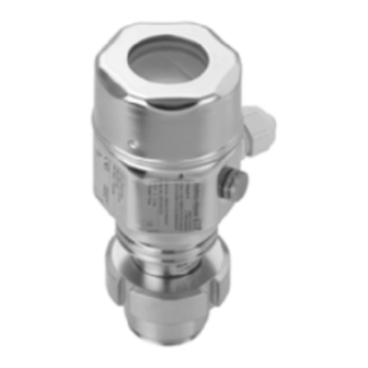
Endress+Hauser Deltapilot M FMB50 Brief Operating Instructions
Hydrostatic level measurement profibus pa pressure sensor with the contite measuring cell (condensate-resistant)
Hide thumbs
Also See for Deltapilot M FMB50:
- Technical information (80 pages) ,
- Brief operating instructions (48 pages) ,
- Operating instructions manual (145 pages)
Table of Contents
Advertisement
Quick Links
KA01034P/00/EN/06.21-00
71549534
2021-09-30
Products
Brief Operating Instructions
Deltapilot M FMB50, FMB51,
FMB52, FMB53
Hydrostatic level measurement
PROFIBUS PA
Pressure sensor with the CONTITE™ measuring cell
(condensate-resistant)
These Brief Operating Instructions are not a substitute for the
Operating Instructions pertaining to the device.
Detailed information about the device can be found in the
Operating Instructions and the additional documentation.
Available for all device versions via
• Internet:
www.endress.com/deviceviewer
• Smartphone/tablet: Endress+Hauser Operations app
Solutions
Services
Advertisement
Table of Contents

Related Manuals for Endress+Hauser Deltapilot M FMB50


Summary of Contents for Endress+Hauser Deltapilot M FMB50
- Page 1 Products Solutions Services KA01034P/00/EN/06.21-00 71549534 2021-09-30 Brief Operating Instructions Deltapilot M FMB50, FMB51, FMB52, FMB53 Hydrostatic level measurement PROFIBUS PA Pressure sensor with the CONTITE™ measuring cell (condensate-resistant) These Brief Operating Instructions are not a substitute for the Operating Instructions pertaining to the device.
-
Page 2: Associated Documentation
Associated documentation Deltapilot M FMB50, FMB51, FMB52, FMB53 PROFIBUS PA Associated documentation Order code: XXXXX-XXXXXX Ser. no.: XXXXXXXXXXXX Ext. ord. cd.: XXX.XXXX.XX Serial number www.endress.com/deviceviewer Endress+Hauser Operations App A0023555 About this document Document function The Brief Operating Instructions contain all the essential information from incoming acceptance to initial commissioning. -
Page 3: Symbols Used
Deltapilot M FMB50, FMB51, FMB52, FMB53 PROFIBUS PA About this document Symbols used 2.2.1 Safety symbols DANGER This symbol alerts you to a dangerous situation. Failure to avoid this situation will result in serious or fatal injury. WARNING This symbol alerts you to a dangerous situation. Failure to avoid this situation can result in serious or fatal injury. -
Page 4: Basic Safety Instructions
The manufacturer is not liable for damage caused by improper or non-intended use. Verification for borderline cases: ‣ For special fluids and fluids for cleaning, Endress+Hauser is glad to provide assistance in verifying the corrosion resistance of fluid-wetted materials, but does not accept any warranty or liability. -
Page 5: Operational Safety
It fulfills general safety requirements and legal requirements. It also conforms to the EC directives listed in the device-specific EC declaration of conformity. Endress+Hauser confirms this fact by applying the CE mark. Endress+Hauser... -
Page 6: Incoming Acceptance And Product Identification
• Do the data on the nameplate correspond to the order specifications and the delivery note? • Is the documentation available? • If required (see nameplate): Are the safety instructions (XA) present? If one of these conditions is not fulfilled, please contact your Endress+Hauser sales office. Storage and transport 4.2.1 Storage conditions Use original packaging. -
Page 7: Mounting Requirements
Deltapilot M FMB50, FMB51, FMB52, FMB53 PROFIBUS PA Mounting Mounting Mounting requirements 5.1.1 General installation instructions • Devices with a G 1 1/2 thread: When screwing the device into the tank, the flat seal has to be positioned on the sealing surface of the process connection. - Page 8 Mounting Deltapilot M FMB50, FMB51, FMB52, FMB53 PROFIBUS PA A0028471 • Keep the pressure compensation and GORE-TEX® filter (1) free from contamination. • Do not clean or touch process membranes with hard or pointed objects. • The process membrane in the rod and cable version is protected against mechanical damage by a plastic cap.
- Page 9 Deltapilot M FMB50, FMB51, FMB52, FMB53 PROFIBUS PA Mounting 5.2.2 FMB50 Level measurement • Always install the device below the lowest measuring point. • Do not install the device at the following positions: • in the filling curtain • in the tank outlet •...
- Page 10 Mounting Deltapilot M FMB50, FMB51, FMB52, FMB53 PROFIBUS PA 5.2.3 FMB51/FMB52/FMB53 • When mounting rod and cable versions, make sure that the probe head is located at a point as free as possible from flow. To protect the probe from impact resulting from lateral movement, mount the probe in a guide tube (preferably made of plastic) or secure it with a clamping fixture.
-
Page 11: Supplementary Installation Instructions
Deltapilot M FMB50, FMB51, FMB52, FMB53 PROFIBUS PA Mounting 5.2.4 Mounting the FMB53 with a suspension clamp A0018793 Extension cable Suspension clamp Clamping jaws Mounting the suspension clamp: Mount the suspension clamp (item 2). When selecting the place to fix the unit, take the weight of the extension cable (item 1) and the device into account. -
Page 12: Electrical Connection
Electrical connection Deltapilot M FMB50, FMB51, FMB52, FMB53 PROFIBUS PA 5.2.6 Seal for flange mounting NOTICE Incorrect measurement results. The seal is not allowed to press against the process membrane as this could affect the measurement result. ‣ Ensure that the seal is not touching the process membrane. -
Page 13: Connecting The Device
Deltapilot M FMB50, FMB51, FMB52, FMB53 PROFIBUS PA Electrical connection Connecting the device WARNING Supply voltage might be connected! Risk of electric shock and/or explosion! ‣ Ensure that no uncontrolled processes are activated at the facility. ‣ Switch off the supply voltage before connecting the device. - Page 14 Electrical connection Deltapilot M FMB50, FMB51, FMB52, FMB53 PROFIBUS PA A0029967 External ground terminal Grounding terminal PROFIBUS PA: Supply voltage: 9...32 VDC (Segment coupler) Terminals for supply voltage and signal 6.2.1 Connecting the cable version (FMB50 only) – A0019991 RD = red...
- Page 15 Deltapilot M FMB50, FMB51, FMB52, FMB53 PROFIBUS PA Electrical connection 6.2.2 Connection of devices with M12 plug A0011175 Signal + Not assigned Signal – Ground 6.2.3 Supply voltage PROFIBUS PA Version for non-hazardous areas: 9 to 32 V DC 6.2.4 Current consumption 11 mA ±1 mA, switch-on current corresponds to IEC 61158-2, Clause 21.
-
Page 16: Operation Options
Operation options Deltapilot M FMB50, FMB51, FMB52, FMB53 PROFIBUS PA Operation options Operation without an operating menu Operation options Explanation Graphic Description Local operation The device is operated using the operating → 16 without device display keys and the DIP switches on the electronic... -
Page 17: Function Of The Operating Elements
Deltapilot M FMB50, FMB51, FMB52, FMB53 PROFIBUS PA Operation options Function of the DIP switches Symbol/labeling Switch position "off" "on" The device is unlocked. Parameters relevant to The device is locked. Parameters relevant to the the measured value can be modified. - Page 18 Operation options Deltapilot M FMB50, FMB51, FMB52, FMB53 PROFIBUS PA Operation with device display (optional) A 4-line liquid crystal display (LCD) is used for display and operation. The local display shows measured values, dialog texts, fault messages and notice messages. For easy operation the display can be taken out of the housing (see figure steps 1 to 3).
- Page 19 Deltapilot M FMB50, FMB51, FMB52, FMB53 PROFIBUS PA Operation options – A0030013 Main line Value Symbol Unit Bar graph Information line Operating keys The following table illustrates the symbols that can appear on the local display. Four symbols may appear at the same time.
- Page 20 Operation options Deltapilot M FMB50, FMB51, FMB52, FMB53 PROFIBUS PA 7.2.1 Operating keys on the display and operating module Operating key(s) Meaning • Navigate down in the picklist • Edit the numerical values or characters within a function A0017879 • Navigate up in the picklist •...
- Page 21 Deltapilot M FMB50, FMB51, FMB52, FMB53 PROFIBUS PA Operation options Menu path: Setup → Extended setup → Current output → Set URV Set URV Operation The local display shows the parameter to be changed. The "mbar" unit is 1 0 0 . 0 0 0 mbar defined in another parameter and cannot be changed here.
-
Page 22: Commissioning With An Operating Menu
Commissioning Deltapilot M FMB50, FMB51, FMB52, FMB53 PROFIBUS PA Commissioning The device is configured for the "Level" measuring mode as standard. The measuring range and the unit in which the measured value is transmitted correspond to the data on the nameplate. - Page 23 Deltapilot M FMB50, FMB51, FMB52, FMB53 PROFIBUS PA Commissioning Press. eng. unit (125) Write permission Operator/Maintenance/Expert Description Select the pressure unit. If a new pressure unit is selected, all pressure-specific parameters are converted and displayed with the new unit. Selection •...
-
Page 24: Write Permission
Commissioning Deltapilot M FMB50, FMB51, FMB52, FMB53 PROFIBUS PA Description Pos. zero adjustment – the pressure difference between zero (set point) and the measured pressure need not be known. Example • Measured value = 2.2 mbar (0.033 psi) • You correct the measured value via the "Pos. zero adjust"... -
Page 25: Configuring Pressure Measurement
Deltapilot M FMB50, FMB51, FMB52, FMB53 PROFIBUS PA Commissioning Configuring pressure measurement 8.2.1 Calibration without reference pressure (dry calibration) Example: In this example, a device with a 400 mbar (6 psi) sensor is configured for the 0 to +300 mbar (0 to 4.5 psi) measuring range, i.e. are assigned 0 mbar and 300 mbar (4.5 psi) respectively. - Page 28 *71549534* 71549534 www.addresses.endress.com...
Need help?
Do you have a question about the Deltapilot M FMB50 and is the answer not in the manual?
Questions and answers